UNIVERSITE DE SHERBROOKE
Faculte de Genie
Departement de Genie Chimique
THEORETICAL STUDY OF NANOPARTICLE
FORMATION IN THERMAL PLASMA PROCESSING:
NUCLEATION, COAGULATION AND AGGREGATION
ETUDE THEORIQUE DE LA FORMATION DE
NANOPARTICULES DANS DES PROCEDES PLASMA:
NUCLEATION, COAGULATION ET AGREGATION
These de doctorat es sciences appliquees
Speciality Genie Chimique
Composition du jury:
Jean Frangois Bilodeau Examinateur
Martin Bolduc Examinateur
Frangois Gitzhofer Rapporteur
Pierre Proulx Directeur de these
Norma Yadira MENDOZA GONZALEZ
1*1
Library and
Archives Canada
Published Heritage
Branch
395 Wellington Street Ottawa ON K1A0N4 CanadaBibliotheque et
Archives Canada
Direction du
Patrimoine de I'edition
395, rue Wellington Ottawa ON K1A0N4 CanadaYour file Votre reference ISBN: 978-0-494-42687-6 Our file Notre reference ISBN: 978-0-494-42687-6
NOTICE:
The author has granted a
non-exclusive license allowing Library
and Archives Canada to reproduce,
publish, archive, preserve, conserve,
communicate to the public by
telecommunication or on the Internet,
loan, distribute and sell theses
worldwide, for commercial or
non-commercial purposes, in microform,
paper, electronic and/or any other
formats.
AVIS:
L'auteur a accorde une licence non exclusive
permettant a la Bibliotheque et Archives
Canada de reproduire, publier, archiver,
sauvegarder, conserver, transmettre au public
par telecommunication ou par I'lnternet, prefer,
distribuer et vendre des theses partout dans
le monde, a des fins commerciales ou autres,
sur support microforme, papier, electronique
et/ou autres formats.
The author retains copyright
ownership and moral rights in
this thesis. Neither the thesis
nor substantial extracts from it
may be printed or otherwise
reproduced without the author's
permission.
L'auteur conserve la propriete du droit d'auteur
et des droits moraux qui protege cette these.
Ni la these ni des extraits substantiels de
celle-ci ne doivent etre imprimes ou autrement
reproduits sans son autorisation.
In compliance with the Canadian
Privacy Act some supporting
forms may have been removed
from this thesis.
While these forms may be included
in the document page count,
their removal does not represent
any loss of content from the
thesis.
• * •
Conformement a la loi canadienne
sur la protection de la vie privee,
quelques formulaires secondaires
ont ete enleves de cette these.
Bien que ces formulaires
aient inclus dans la pagination,
il n'y aura aucun contenu manquant.
RESUME
Ce travail presente une etude theorique de la synthese de nanoparticules dans des reacteurs plasmas a induction haute frequence (RF-ICP). Le but est d'etudier l'infiuence des parametres du procede sur la taille finale et la morphologie des particules produites. Le modele propose se veut aussi complet que possible et implique le calcul des champs de l'ecoulement et de la temperature du gaz plasma. L'evaporation de particules mi-crometriques (precurseurs) est representee par la trajectoires des particules et l'historique de temperature calcules avec une approche Lagrangienne. La formation des nanoparticules est consideree par la nucleation homogene et la croissance est due a la condensation et a la coagulation Brownienne. La croissance des agregats de nanoparticules est modelisee par l'utilisation de la geometrie fractale qui est une des contributions importantes de ce travail. Le transport des nanoparticules sc produit par convection, thcrmophorese et diffusion Brownienne. La methode des moments est utilisee pour resoudre l'equation de la dynamique des particules, qu'elles soient dans le regime de croissance par coalescence ou par agregation fractale. Le modele est compare aux resultats experimentaux disponibles dans une gamme de conditions d'operation et de geometries de reacteurs. Les resultats issus de cette etude sont presentes en deux parties.
La premiere partie de ce travail est basee sur l'utilisation du logiciel Fluent 6.1 com-bine a un module specialise sur les aerosols, developpe par la compagnie Chimera, appelle Fine Particle Model (FPM). Cette approche de modelisation simplifiee est utilisee pour etudier de facon globale la relation entre les parametres de fonctionnement et les proprietes des nanoparticules produites lors d'essais a l'echelle du laboratoire.
La deuxieme partie presente un modele hybride couple de la synthese de nanopartic-ules spheriqucs et des agregats formes par ces nanoparticnanopartic-ules dites primaires. Les resultats obtenus a partir de cc modele permettront d'identifier le role de chacun des parametres dans la definition de la morphologie fractale des nanoparticules.
Les resultats numeriques obtenus a partir de la solution du modele ont ete effectues sur la base des geometries des reacteurs utilises au laboratoire. En outre, cette etude permet de demontrer l'importance de l'ecoulement et des champs de temperature sur la croissance des particules primaires et des agregats.
ABSTRACT
This work presents a mathematical modeling study of the synthesis of nanoparticles in radio frequency (RF) inductively coupled plasma (ICP) reactors. The purpose is to further investigate the influence of process parameters on the final size and morphology of produced particles. The proposed model involves the calculation of flow and temperature fields of the plasma gas. Evaporation of raw particles is also accounted with the particle trajectory and temperature history calculated with a Lagrangian approach. The nanoparticle formation is considered by homogeneous nucleation and the growth is caused by condensation and Brownian coagulation. The growth of fractal aggregates is considered by introducing a power law exponent Df. Transport of nanoparticles occurs by convection, thermophoresis and Brownian diffusion. The method of moments is used to solve the particle dynamics equation.
The model is validated using experimental results from plasma reactors at laboratory scale. The results are presented in the following manner.
First, use is made of the computational fluid dynamics software (CFD), Fluent 6.1 with a commercial companion package specifically developped for aerosols named: Fine Particle Model (FPM). This package is used to study the relationship between the operating parameters effect and the properties of the end products at the laboratory scale.
Secondly, a coupled hybrid model for the synthesis of spherical particles and fractal aggregates is developped in place of the F P M package. Results obtained from this model will allow to identify the importance of each parameter in defining the morphology of spherical primary particles and fractal aggregates of nanoparticles.
The solution of the model was made using the geometries and operating conditions of existing reactors at the Centre de Recherche en Energie, Plasma et Electrochimie (CREPE) of the Universite de Sherbrooke, for which experimental results were obtained experimentally. Additionally, this study demonstrates the importance of the flow and temperature fields on the growth of fractal particles; namely the aggregates.
This thesis is dedicated to the memory of...
Pomposita Derio Lopez
Andres Gonzalez Lopez
A C K N O W L E D G M E N T S
This research project would not have been possible without the support of valuable people.
I would like to thank first and foremost my advisor, Dr. Pierre Proulx, whose exper-tise, understanding, and patience, added considerably to my graduate experience. It was through his intellectual advice and kindness that I completed my master degree and I was encouraged to apply for a PhD degree.
Special thanks to the members of the supervisory committee, Dr. Jean Frangois Bilodeau, Dr. Martin Bolduc and Dr. Frangois Gitzhofer. I really appreciate the time involved in the reading and the correction of this thesis.
I deeply acknowledge my colleagues Dr. Mbark El Morsli and Dr. Siwen Xue, for their assistance in the plasma modeling part of this work. Appreciation also goes out to my colleagues Isabelle Bolduc, Brahim Selma, Rachid Bannari, and Dr. Abdel Bannari for all rich discussions in which their assistance helped me along the way.
So much thanks to the Chemical Engineering department staff: France Auclair, An-dree Paradis, Sylvie Lebrun and Louise Chapdelaine, who always brought me an efficient and kind help concerning the administrative duties during my studies. I must also ac-knowledge Mr. Peter Lanigan, who was always available when I needed urgent professional English writing corrections.
Not forgetting all my friends who were always close. Specially Dr. Laura Merlo and Dr. German Cota, who are responsible I got involved on the Plasma field.
I would like to thank my parents, Mauro Mendoza and Joaquina de Jesus Gonzalez for instilling in me confidence for pursuing my dreams.
My sisters Nadia, Marlene and Guadalupe who offered me unconditional love and support throughout the accomplishment of my graduated studies.
was with his love, encouragement and patience, that the carrying of this thesis was easier. I recognize that this research would not have been possible without the financial as-sistance of the CONACYT from Mexico, the CRSNG and the Fondation Force. I express my gratitude to those agencies.
Contents
1 I N T R O D U C T I O N 1 1.1 Nanoparticles and Nanotechnology 1
1.2 Nanoparticles production by thermal plasma 3
1.3 Thermal Plasma 4 1.3.1 DC Plasma Torches 6
1.3.2 RF Inductively Coupled Plasma Torches 7 1.4 Modeling of nanoparticle growth in thermal plasma reactors 9
1.5 Framework and objectives of this thesis 10
1.6 Contributions 11 1.7 Contents 12 References 14 2 THEORY 17 2.1 Plasma model 17 2.2 Turbulence model 22
2.2.1 k-epsilon Model 24 2.3 Particle evaporation model 25
2.4 The Aerosol Model 31 2.4.1 Review of current aerosol modeling techniques 34
2.5 The Aerosol Model by FPM 39 2.5.1 The particle dynamics 41 2.5.2 Particle dynamics processes 41 2.5.3 Particle distribution representation 42 2.5.4 The moment dynamics equation 44
2.5.5 Transport by convection 45 2.5.6 Transport by external forces 45 2.5.7 Transport by diffusion 47 2.5.8 Coagulation and coalescence 47 2.5.9 Brownian coagulation 48 2.5.10 Condensation and evaporation 48
2.5.11 Homogeneous nucleation 50 2.6 Fractal agglomeration model 52
References 59
3 N U M E R I C A L S T U D Y OF THE SYNTHESIS OF N A N O P A R T I C L E S IN
A N ICP R E A C T O R 63
3.1 Abstract 64 3.2 Introduction 64
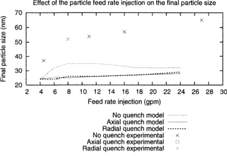
3.3 Numerical model 65 3.3.1 Fluid mechanics 65 3.3.2 Nanoparticle model 67 3.3.3 Results and discussion 68 3.3.4 Effect of feed rate injection on final particle size 70
3.3.5 Conclusion 72
References 73
4 N U M E R I C A L SIMULATION OF SILICA N A N O P A R T I C L E S
PRO-D U C T I O N IN A R F P L A S M A REACTOR: EFFECT OF Q U E N C H 75 4.1 Abstract 76 4.2 Introduction 76 4.3 Numerical model 77 4.3.1 Particle evaporation 79 4.3.2 Nanoparticle growth 80 4.4 Results and discussion 81
4.4.1 Comparison of numerical results to experimental cases 84
4.5 Conclusion 85 References 86
5 P R O D U C T I O N OF NANOPARTICLES IN T H E R M A L P L A S M A S : A MODEL I N C L U D I N G EVAPORATION, NUCLEATION, C O N D E N S A
-TION A N D FRACTAL A G G R E G A T I O N 88
5.2 Introduction 89 5.3 Model 91
5.3.1 Plasma Model 93 5.3.2 Turbulence model 98 5.3.3 Particle Evaporation Model 99
5.3.4 Nanoparticle model 104 5.3.5 The method of moments 108
5.4 Solution method 115 5.4.1 Transport properties and boundary conditions 116
5.4.2 Numerical procedure 118 5.5 Results and Discussion 119
5.5.1 Plasma generation and particle evaporation 120
5.5.2 Effect of nanoparticle growth 125 5.5.3 Effect of particle aggregation 131 5.5.4 A reactor design for spherical non-aggregated nanoparticles 132
References 138
List of Figures
1.1 DC plasma torch 6 1.2 RF plasma torch 7
2.1 Scheme of aerosol modeling 34 2.2 Aerosol simulation techniques 40 2.3 Particle processes occurring within and at the boundaries of a single control
volume 41
3.1 Schematic illustration of the ICP synthesis reactor 66 3.2 a) Temperature contours (K), b) Pathlines of silica mass fraction 70
3.3 a) Particle density (number of particles/m?), b) Particle mean diameter (nm) 71
3.4 Effect of the particle injection feed rate on final particle sizes 72
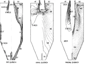
4.1 Schematic illustration of the RF synthesis reactor 78 4.2 Temperature, turbulent viscosity ratio and mass fraction contours: a) Case
without quench, b) Case with axial quench 81 4.3 Particle number density distribution (/m ) and particle diameter (nm)
4.4 a)SEM picture of final particle size (nm) for the case without quench; b) Numerical histogram plot of particle diameter for the case without quench; c) SEM picture of final particle size (nm) for the axial quench case; d) Numerical
histogram plot of particle diameter for the axial quench case 84
5.1 ICP nanopowder synthesis reactor at the CRTP of the University de Sherbrooke 92
5.2 Schematic illustration of the ICP synthesis reactor 94
5.3 Grid reactor 117 5.4 Temperature contours (K) 121
5.5 Stream function contours 122 5.6 Turbulent viscosity ratio 123 5.7 Mass fraction contours 126 5.8 Temperature history of silica particles injected into argon/oxygen plasma (NO
QUENCH) 127 5.9 Temperature history of silica particles injected into argon/oxygen plasma
(RADIAL QUENCH) 127 5.10 Temperature history of silica particles injected into argon/oxygen plasma
(AXIAL QUENCH) 128 5.11 Influence of particle injection rate on temperature fields 129
5.12 Numerical diameter (m) after nucleation 130 5.13 Numerical diameter (m) after nucleation -) condensation 130
5.14 Numerical diameter (m) after nucleation -h condensation f coagulation . . . . 131
5.15 Average number of primary particles per aggregate 132
5.16 Wall tube temperature contours (K) 133 5.17 Wall tube mass fraction contours 134
List of Tables
1.1 Characteristic of DC Plasma and RF Plasma Torches 8
2.1 Fluid flow and temperature field assumptions 18 2.2 Particle evaporation model assumptions 26
5.1 Fluid flow and temperature field assumptions 95 5.2 Particle evaporation model assumptions 100 5.3 Silica vapor concentration and nanoparticle model assumptions 109
5.4 Source terms for the moments of the PSDF 116 5.5 Injection properties for the silica raw particles 117
5.6 Physical properties for silica 118 5.7 Summary of comparison between numerical and experimental results 133
Chapter 1
INTRODUCTION
1.1 Nanoparticles and Nanotechnology
The production of nanomaterials [1] offering new properties because of their size in a length scale less than 100 nm clearly seems one of the nanotechnologies which, in short and medium term, will produce a major impact in terms of industrial applications.
Nanomaterials are usually produced by compaction of a powder of nanoparticles. They are characterized by a large number of grain boundary interfaces in which the local atomic arrangements are different from those of the crystal lattice (Weissmuller, 1996 [2]). The small size of the nanoparticles makes them suitable for new applications because of their different properties compared to the bulk materials. Examples of these new properties include lower melting temperature, increased solid-solid phase transition pressure, higher self-diffusion coefficient, catalytic activity, etc. (Kruis et al 1998 [3]).
Nanoscalc materials engineering will therefore have an increasingly important impact on a number of sectors. The examples cited below show how fields, including biotechnology,
electronics, energy, and industrial products, will benefit from the nanotechnology progress:
- Advanced computing: Nanoelectronic devices based on quantum dots, nanowires and molecular switches will enable the next-generation computer chips.
- Cancer treatment: Nanoparticles are being developed for the targeting and destruction of breast cancer cells.
- Energy storage: Cathodes fabricated from nanomaterials promise rechargeable batteries with longer lifetimes.
- Engineered textiles: Nanofibers improve the properties of lightweight protective clothing for public safety and defense professionals.
- Environment: Nanomaterial-based photocatalysts clean the environment and yield surfaces with self-cleaning properties.
- Packaging: Nanocomposite barrier plastics can increase the shelf life of various foods and beverages.
- Pharmaceuticals: Antimicrobial nanocoatings on wound dressings kill bacteria, reduce inflammation and promote healing.
In recent years, technical presentations on nanoparticles synthesis and the viable methods of their production have been significantly increased (Kruis et al 1998 [3]). Nanoparticles can be synthesized using gas-phase (Swihart 2003 [4], Hahn 1997 [5]) or liquid-phase processes. Both methods are routinely used in industry to manufacture a large variety of nanoparticle powders. Other examples of synthesis methods are mechanical attrition, laser ablation, sputtering, and chemical precipitation.
Synthesis methods in the gas phase Gas-phase processes are considered a better route
for the synthesis of particles. Kruis et al. 1998 [3] presented a brief comparison between gas-phase and liquid phase processes emphasizing the next aspects:
(a) Gas-phase processes are generally purer than liquid-based processes since even the most ultra-pure water contains traces of minerals, detrimental for electronic grade semicon-ductors. These impurities seem to be avoidable only in vacuum and gas-phase systems. (b) Aerosol processes have the potential to create complex chemical structures which are
useful in producing multicomponent materials, such as high-temperature superconduc-tors.
(c) The process and product control are usually very good in aerosol processes. Particle size, crystallinity, degree of agglomeration, porosity, chemical homogeneity, stoichiometry, all these properties can be controlled with relative ease by either adjusting the process parameters or adding an extra processing step.
(d) Gas-phase processes for particle synthesis are usually continuous processes, while liquid-based synthesis processes or milling processes are often performed in a batch form.
Most synthesis methods of nanoparticles in the gas phase are based on homogeneous nucleation in the gas phase and subsequent condensation and coagulation. Once the homogeneous nucleation is initiated, many nanosized nuclei can result and upon cooling nanoparticles will yield.
1.2 Nanoparticles production by t h e r m a l p l a s m a
The vapor phase method using the thermal plasma technology is considered as a suitable method to produce monodisperse nanoparticles (Girshick et al., 1993 [18]). This method
can deliver the energy necessary to cause evaporation or initiate chemical reaction. The plasma temperatures are in the order of 104 K, decomposing the reactants into ions and
dissociating atoms in radicals. A solid powder feed can be injected and it is decomposed by the plasma. Nanoparticles are formed upon cooling while exiting the plasma region. Main types of the thermal plasmas are dc plasma jet, dc arc plasma and rf induction plasma (Boulos, 1997 [7]). Beside these techniques, a wide variety of metallic and ceramic nanoparticles have been synthesized in plasma reactors (da Cruz et al, 2001 [8]; Girshick et al, 1993 [18]; Soucy, 1992 [9]; Laflamme et al, 1992 [10]).
Radio-Frequency (RF) Inductively Coupled Plasma (ICP) process is an efficient tech-nique by which metallic and ceramic materials are produced with sizes in the nanometer range. The control and understanding of such process is still a challenge for the indus-trial technology and from a theoretical standpoint. The control of nanoparticles synthesis is difficult because of the fast and complex phenomena involved in this process. In recent years, several studies related to the understanding of this technology brought significant progress. Nevertheless, one of the main problems remains the industrial scale-up of the process. Modeling studies can play an important role in the understanding and control of particle morphology, particle size, size distribution, and phase composition, which are im-portant characteristics determining the quality of the produced nanoparticles. An adequate understanding of the fluid mechanics through Computational Fluid Dynamics (CFD) pro-vides an important tool with considerable predictive power in terms of scale-up and process optimization.
1.3 Thermal Plasma
A plasma gas consists in a mixture of electrons, ions and neutral species. Although there are negative and positive free charges, these particles compensate each other in such a way that the plasma becomes electrically neutral. This plasma property is known as quasi-neutrality.
In comparaison to a gas, the free charges of the plasma enhance the electrical conductivity. The plasma conductivity may even overcome that of metals.
Plasmas can be generated by a process known as electrical breakdown. This process consists in passing an electric current through a gas in order to produce a given percentage of charge carriers and make the gas electrically conductive. For instance, plasmas can be produced by an electric-arc discharge, electrodeless radio frequency (RF) discharge, shock waves, microwaves, laser or high-energy beams. Specifically, plasmas produced by electric-arc discharges are divided in two categories.
The first plasma type is known as non-equilibrium or cold plasma. These plasmas are characterized by their low-energy density and the large difference between the temperature of electrons and heavy particles (Te > >T/j). Cold plasmas are also characterized by
their low electron density (less than 1020 m- 3) and their high electron temperature, which
can reach several electron-volts (eV). Typical cold plasma examples are those produced in low-pressure RF, and in glow and corona discharges.
The second category is called an equilibrium or thermal plasma. These plasmas are characterized by their high-energy density and the equality between the temperature of heavy species and electrons (T/j — Te). In other words, the thermodynamic state of the
plasma approaches a local thermodynamic equilibrium (LTE). Thermal plasmas are also characterized by having a relatively high electron density in the range of 1023 - 1028 m~3
and low electron energy in the range of 1 - 2 eV. Typical thermal plasma examples are those produced in high-intensity arcs and in plasma torches, such as radio-frequency (RF) inductively-coupled discharges or direct current (DC) discharges.
thermal plasma for which we are mostly concerned. Among the most commonly used plasma-generating devices in material synthesis processes, there are the direct current (DC) plasma torch and the RF inductively-coupled plasma torch. These torches operate simultaneously as a source of activated species and thermal energy, which is used in material synthesis and processing.
1.3.1 DC Plasma Torches
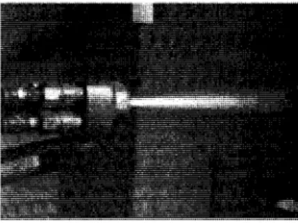
DC plasma torches comprise three main elements; the cathode, the plasma-forming gas injection and the anode. A typical picture of a DC plasma torch is shown in Figure 1.1
Figure 1.1: DC plasma torch
Two different types of DC torches are commonly used: torches with hot cathode and torches with cold cathode. The first type uses cold copper electrodes for both cathode and anode in a co-axial tubular arrangement. The co-axial electrodes are separated by a small gap in which the plasma-forming gas is introduced. A strong vortex motion is used to ensure the continuous motion of the arc root and to reduce erosion. These DC torches allow the use of oxidizing plasma-forming gases. The second type is called hot cathode torches. These torches usually use a thoriated tungsten cathode and annular copper anode. They are used at power level below 100 kW and cannot be used with oxidizing plasma-forming gases since it can damage the tungsten cathode. Some typical performance parameters of DC plasma torches are given in Table 1.1.
1.3.2 RF Inductively Coupled Plasma Torches
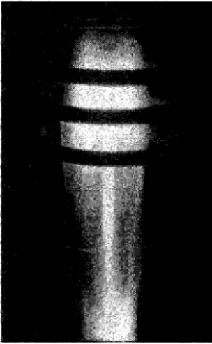
In RF induction plasma torches, the energy coupling to the plasma is accomplished by the electromagnetic field produced by an induction coil ( [11], [12], [7]). Because in these torches the plasma-forming gas does not come into contact with any kind of electrodes, contamination sources from the electrode materials are eliminated. These type of torches also allow the use of a wide range of plasma-forming gases, including corrosive atmospheres. A typical RF plasma torch is usually implemented with a water-cooled quartz or a ceramic plasma confinement tube. The tube is surrounded by a 3 to 7-turn induction coil. The induction coil is connected to the RF power supply through the tank circuit. Figure 1.2 shows a quartz tube induction plasma torch developed at the CREPE of the Universite de Sherbrooke.
Figure 1.2: RF plasma torch
The stability of the discharge in the center of the coil is ensured by the use of three gaseous streams introduced upstream of the torch through a gas distributor head. The different gaseous streams are the sheath gas, the intermediate gas and the powder gas. The sheath gas protects the plasma confinement tube by reducing the heat flux from the plasma to the ceramic tube walls. The intermediate gas is introduced into the discharge with both axial and tangential velocity components to stabilize the plasma. The powder
gas is injected axially to the center of the discharge using a water-cooled probe, and carries the material to be treated.
Several advantages of the RF plasma torch may be summarized as follow:
• The induction plasma presents a relatively large plasma volume. This favors high throughputs of reactant.
• A better control of the processing conditions at high throughputs is achieved due to the low velocity of the discharge and the easy access in the axial injection of raw materials into the plasma.
• The absence of electrodes allows the use of a wide range of plasma-forming gases, including inert, reducing, oxidizing, and corrosives.
• The long residence time of the particles into the discharge makes the induction plasma an ideal system for in-flight melting and vaporization of relatively large metal and ceramic powders.
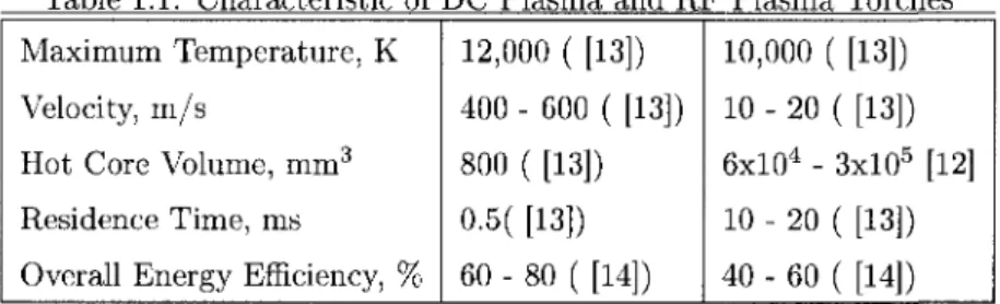
Table 1.1 shows a performance comparison between typical DC and RF induction plasma torches.
Table 1.1: Characteristic of Maximum Temperature, K Velocity, m/s
Hot Core Volume, mm3
Residence Time, ms
Overall Energy Efficiency, %
DC Plasma and R 12,000 ( [13]) 400 - 600 ( [13]) 800 ( [13]) 0.5( [13]) 60 - 80 ( [14]) 7 Plasma Torches 10,000 ( [13]) 10 - 20 ( [13]) 6xl04 - 3xl05 [12] 10 - 20 ( [13]) 40 - 60 ( [14])
1.4 Modeling of nanoparticle growth in thermal plasma
reac-tors
Modeling studies can play an important role in the development and improvement of nanoparticle synthesis processes. Furthermore, models can provide an insight into these aerosol processes, and thus help to identify essential factors in various applications. In the following, we report on the modeling studies of nanoparticle synthesis by plasma that have been published over the last two decades.
Modeling studies of the production of nanoparticles in radio-frequency ICP [15,17-19, 31] and direct-current plasmas [20,21] date back to less than 20 years. Most models are based on homogeneous nucleation in the gas phase with subsequent condensation and coagulation. [22] reported that the injection of solid particles into the plasma produce a local cooling effect on the temperature field. By increasing the alumina feed rate from 1 to 50 gmin"1, [22]
demonstrated the maximum particle temperature drops from 3800 K to less than 800 K. On the other hand, the solid vapor concentration increases, and thus the growth of the particles increases, by increasing the injection feed rate [18]. The model, of [18] considers the major growth mechanisms in the formation of ultrafine iron powders in a thermal plasma reactor. The contributions of thermophoresis and radial diffusion are included in the conservation equations for the distribution moments. [23] clarified by numerical investigation how the number density, diameter and specific surface of the produced metallic nanoparticles of Al, Ti, Au, and Pt are influenced by the operating conditions, such as the quenching gas flow rate and the powder feed rate of the RF-ICP reactor. [23] also reported that for all metals, the increase of the quenching gas flow rate results in the increase of the particle number density, the decrease of the mean diameter and the increase of the specific surface.
The effect of the initial concentration of yhe metal vapor and the quenching flow rate were investigated by [24]. The results obtained by [24] show that the increased flow rate of the quench gas causes a decrease in the particles mean diameter. This is due to both
the cooling and dilution associated with the gas injection. The growth model proposed by [24,25] focus on the particle growth along streamlines or trajectories. This approach accounts for radial nonuniformities but does not allow vapors and particles diffusion downstream of the nucleation line. Other two-dimensional growth models [26-30] in the aerosol literature consider radial diffusion of vapors and particles. By neglecting the axial diffusion limits the application of these models is limited to non-recirculating flows.
A more sophisticated two-dimensional model was developed by [31] for predicting the growth and transport of ultrafine powders in the cooling zone of an induction plasma reactor. Particle nucleation, growth by surface condensation and Brownian coagulation are considered in the model of [31]. The contributions due of the Brownian diffusion and thermophoresis in the axial and radial directions are also included. The effect of metallic precursor particles feedrate and quench flow rate have been studied by [31]. In this study, the analysis of the growth mechanisms shows the high sensitivity of the model in the estimation of the nucleation rate and the high importance of growth by surface condensation. Thermophoresis is found to be the most important mechanism responsible for particle deposition on the reactor walls. Several recent studies have been directed to the design of improved plasma reactors, with the size, morphology, chemical, and structural aspects of the powders as a function of the reactors operating conditions [23,32-36].
1.5 Framework and objectives of this thesis
There is a clear technological interest in generating nanoparticles of well controlled sizes and morphologies at high rates. Due to the difficulties in the scale-up of thermal plasma technologies, the development of new modeling tools appears as a necessity in nanoparticle synthesis.
The first objective of this work is to develop a modeling tool that can be used to further explore and study the production of nanoparticle production not only at laboratory
scale but that could also be used in a strategy to scale up the industrial process. The development of this model involves the use of the aerosol module (FPM) incorporated in Fluent 6.1.
The second objective is to study the formation of fractal particles formed by nucle-ation, condensation and fractal coagulation. For this purpose, a coupled complete model, using Fluent 6.2 as a computational code, is proposed.
The models developed in the current study rely strongly on experimental results previously obtained by [37] in our laboratory. The model's operating conditions, geometries, and overall parameters are also based on these experiments.
1.6 Contributions
Significant contributions issued from this work may be summarized as follow:
- Implementation in Fluent of the aerosol package FPM to radio-frequency inductively-coupled plasma reactors. The use of FPM to RF-ICP reactors enables one to obtain fast and reasonably accurate predictions of the effect of operating parameters and the properties of the nanoparticles. This model can be used very efficiently to better analyze experimental results and to improve the design of reactors.
- The development of a fractal model taking into account the aggregation of primary particles into aggregates. By implementing a fractal model, the present model can be used to better determine the influence of parameters and their effect on the final size and, very importantly, morphology of the particles.
One of the very interesting aspects in the present thesis is its strong connection with the thesis of [37], which was mostly oriented towards experiments and design. Equally important, the development of a fractal model with the method of moments makes this thesis a more complete tool than the previously existing mathematical modeling tools. In this instance, the present theoretical study provides a diagnostic tool with considerable predictive power in terms of scale-up and process optimization, showing directions to obtain the desired nanostructured material.
1.7 Contents
The thesis is presented in the following 6 chapters.
Chapter 1 describes the thermal plasma uses in the production of nanoparticles. The usefulness of modeling works is highlighted and the objectives, contributions and structure of this thesis is outlined.
Chapter 2 summarizes the basic theoretical concepts to build up the plasma flow, particle evaporation and aerosol models.
Chapter 3 and 4 present the results obtained from the model coupled to the FPM. A validation of the model is made through a systematic comparison of available experimental results. The influence of raw particle injection rates and quench injection design are studied.
Chapter 5 presents the results obtained with the fractal model. Primary particles size and aggregates morphology are analyzed as a function of the different quench methods used.
Bibliography
[I] Becker R and Dring W 1935 Annals of Physics, Vol.93 pp.719-752
[2] Weissmuller J 1996 Nanomaterials: Synthesis, Properties and Applications Institute of Physics Publishing, U.K. pp.219-276
[3] Kruis F W, Fissan H and Poled A. 1998 Journal of Aerosol Science Vol.29 5 / 6 pp. 511-535
[4] Swihart M T 2003 Current Opinion in Colloid and Interface Science Vol. 8 127-133 [5] Hahn H 1997 NanoStructured Materials Vol. 9 3-12
[6j Girshick S.L., Chiu C.P., Muno R., Wu C.Y., Yang L., Singh S.K. and Mcmurry P.H. 1993 J. Aerosol Sci. Vol. 24 367-382
[7] Boulos M.I. 1997 High Temp Mat Proces Vol. 1 17-39 [8] Da Cruz A. C. and Muriz R. J. 2001 KONA Vol. 17 85-94
[9] Soucy G 1992 Synthese de Poudres Ultrafines de S^iV^ par Plasma Inductif Vol. P h D
Thesis, Universite de Sherbrooke 233 p
[10] Laflamme C, Soucy G, Jurewicz J and Boulos M I 1992 J. High Temp. Chem. Proces Vol. 1 293-301
[12 [13. [14 [15 [16 [17 [18 [19 [20 [21 [22 [23 [24 [25 [26 [27; [28
Boulos M.I. 1985 High Temperature Chemical Processes Vol. 1 401-411 Boulos M.I. 1991 IEE Transaction on Plasma Science Vol. 19 (6) 1078-1089
Pfender E., Boulos M.I., Fauchais P. 1989 Methods and Principles of Plasma Generation in Chapter 4 in Plasma Technology in Metallurgical Processing, 27-47
Proulx P and Bilodeau J F 1991 Plasma Chemistry and Plasma Processing 11 371 Bilodeau J F and Proulx P 1996 Aerosol Science and technology, 24, No.3, pp. 175-189 Dosilets M, Bilodeau J F and Proulx P 1997 J.Phys.D:Appl.Phys 30, pp 1951
Girshick S L, Chiu C P, Muno R, Wu C Y, Yang L, Singh S K, McMurry P H 1993 J. Aerosol Sci., 24(3), 367-382
Girshick S L and Chiu C P 1989 Plasma Chem. Plasma Process., 9, pp.355
Rao N, Micheel B, Hansen D, Fandrey C, Bench M, Girshick S, Heberlein J and Mc-Murry P 1995 Plasma Chem. Plasma Process., 15,No.4, pp.581-606.
Rao N, Micheel B, Hansen D, Fandrey C, Bench M, Girshick S, Heberlein J and Mc-Murry P 1995 J. Mater. Res., 10, pp.2073-2084.
Proulx P, Mostaghimi J and Boulos M I 1987 Plasma chem. Plasma Proc, 7, pp 29-53 Shigeta M, Watanabe T and Nishiyama H 2004 Thin Solid Films 457, pp 192-200 Proulx P and Bilodeau J F 1991 Plasma chem. Plasma Proc, 11, No.3, pp 371-385 Bilodeau J F and Proulx P 1992 J. High Temp. Chem. Proc. Suppi, 1, pp. 141-148. Pratsinis S E, Kodas T T, Dudukovic M P and Friedlander S K 1986 Znd. Eng. Chem. Proc. Des. Deuel., 25 pp.634-642.
Pratsinis S E and Kim K S 1989 J. Aerosol Sci, 20, pp.101-111.
[29] Bai H and Biswas P 1990 J. Aerosol ScL, 2 1 , pp.629-640.
[30] Okuyama K, Ushio R, Kousaka Y, Flagan R C and Seinfeld J H 1990 AIChE ./., 36, pp.409-419.
[31] Bilodeau J F and Proulx P 1996 Aerosol Science and technology, 24, No.3, pp. 175-189 [32] Mendoza Gonzalez N Y, Goortani B M and Proulx P 2007 Materials Science and
En-gineering: C, 27, No. 5-8, pp. 1265-1269
[33] Goortani B M, Mendoza N, Proulx P: Int. Journal of Chemical Reactor Engineering,
4:A33 (2006) 1-18.
[34] Shigeta M and Watanabe T 2007 Thin Solid Films 515, pp 4217-4227 [35] Shigeta M and Watanabe T 2007 J.Phys.D.-Appl.Phys. 40, pp 2407-2419
[36] Shigeta M, Sato T and Nishiyama H 2004 International Journal of Heat and Mass Transfer 47, pp 707-716
[37] B. M. Goortani, 2006 Synthesis and evaluation of the size and the morphology of silicon dioxide nanoparticles in ICP RFplasma reactors P h D Thesis, Universite de Sherbrooke, Quebec, Canada.
Chapter 2
THEORY
A numerical model is considered as a mathematical framework that permits the interaction of complex physical processes to be simulated. In chemical reactors it is often difficult to mea-sure aerosol size distributions because the gases may be either toxic, corrosive, or explosive, or the systems may be operated at low pressures (most aerosol measurement systems operate at near atmospheric pressure). In this case mathematical modeling of aerosol processes is useful for extending the knowledge gained by an otherwise limited set of experimental data. In this section we present the main structure to build a complete model of nanoparticle growth in a RF-ICP reactor.
2.1 P l a s m a model
Most of the works related to the plasma modeling started in the seventies. The model described by [1] assumed a one-dimensional electromagnetic field model. Lately, a new model is expressed in terms of vector potential [2] in which the electromagnetic coupling uses two conservation equations for the real and imaginary parts of the tangential component of the vector potential. The use of an extended-field model was suggested recently by [3].
Table 2.1: Fluid flow and temperature field assumptions - Steady state
- Axi-symmetric flow at atmospheric pressure - Turbulence modeled by the k-epsilon model
- The coil consists of parallel current carrying rings with a circle cross section of 6 mm in diameter. This implies neglecting the axial component of the coil current. - Optically thin plasma under local thermodynamic equilibrium (LTE) conditions - Viscous dissipation and pressure work are neglected in the energy equation - Negligible displacement current
- Particles do not affect the fluid field or the turbulent quantities
In this model, the vector potential equations are solved in an extended domain comprising the plasma region, the plasma confinement tubes, the induction coils themselves, and the external domain. It allows taking the coil design into account more accurately.
Assumptions
The basic assumptions made in the development of the plasma model are summarized in table 2.1:
Equations
In order to study the electromagnetic field generated by the induction coil currents, a two dimensional approach similar to that described in [3] has been used, in which the vector potential has been chosen as the main variable. Under the assumptions listed above, the Maxwell's equations can be written in their general form as follows :
V-E = 0 (2.1.1)
V-H = 0 (2.1.2)
f)Ff
V x £ = - W ^ - (2.1.3)
V x f f = J (2.1.4) where E and if are the electric and magnetic fields, respectively, /L«O is the permeability of
free space and a is the electrical density.
The variable J is the total current density and can be written as:
J ~ Jind + J(coil) (2.1.5)
where Jjn^ = aE is the current density developed in the plasma and the coil by the
induced electric field. J (coil) ls the- current density induced by the voltage applied to the two
ends of the coil.
The potential vector A is related to the magnetic field by the following expression:
IH>H = VxA (2.1.6) Considering that in the absence of an electrostatic charge on the plasma, the scalar potential
function of the vector potential can be written as follows:
E = -°A
„
L 7 )
Using the relation
V x ( V x A ) = V ( V - i ) - V2 J4 (2.1.8)
and the equation of Coulomb's gauge:
V - A = 0 (2.1.9) and substituting Eq.2.1.7 into Eq.2.1.4 gives the following equation for the vector potential:
dA
V2A = fi0<r— (2.1.10)
Using Eq.2.1.5, Eq.2.1.10 can be written as:
V2A = -no (Jind + J{coil)) (2.1.11)
If the current densities in Eq.2.1.11 are known, the analytical solution is as follow:
U n f J(coil) (r,t j + Jind (r,t)
A=^ V , ' T. i J-dv (2.1.12)
47T J \r - r |
where the integration is over all the current carrying regions and dv is the volume element. Assuming that all the fields A, E and H arc sinusoidal with a frequency / in the RF plasma, they can be written as:
A{r,t)=Ac{r)eiut (2.1.13)
E (r, t) = Ec (r) eiu}t (2.1.14)
H(r,t) = Hc(r)eiuJt (2.1.15)
In the equation 2.1.11, the time variation of A and J can be omitted and the equation 2.1.11 remains the same but A and J will not change with time.
The equations 2.1.11, 2.1.13, 2.1.14, and 2.1.15 give:
V2AC - inoaujAc = 0 (2.1.17)
(i0Hc = V x Ac (2.1.18)
Ec = -iujAc (2.1.19)
Assuming that the coil is made of parallel rings, the vector potential A and the electric field E have only an azimuthal component Ac = ( 0 , ^ , 0 ) and Ec = (0,Eg,0).
Ag is a phasor quantity and can be written as:
Ae(r,t) = Ad(r)ei"t (2.1.20)
Therefore,
v I un.gc \ d
—
I
r^r-
1
+-r and Eg can be written as:
i d ( dA6c\ d2A9c (. i \ , n , „1 0 1,
rd~r ( r ^ r J + " a i r " ( v * ™ + ^) 4* = 0 (2-1.21)
Ee = -iuAec (2.1.22)
HoHz = ^—{rAec) (2.1.23)
Mo#r = ~§-z(Aec) (2-1.24)
The phasor Agc has a real part and an imaginary part like:
The equation 2.1.21 has various forms according to each zone of the torch. By taking into account equation 2.1.25, the equation 2.1.21 can be written as follows:
In the plasma zone:
1 d ( dAeR\ d2A0R 1
1 d ( dA„\ SPAei 1 , , _ .. .. . . .
? a? l
r _a r j
+" a ^ " ^
Ae/- ^ ^
=°
(2-
L27) In the air outside of the plasma zone and in the coil zone, we have assumed that the electricconductivity is zero. Moreover, there is no current source, so the real part and imaginary part of the vector potentials have the same form and thus:
1 d ( 8AeR\ , d2Am 1
~W r~ a — + ~ ^ ~ 2 9 ^ « = 0 (2.1.28)
r or \ or J oz* rz
ld_ LdAei) , d2A$I 1
r <9r \ In the coil zone:
r dr \ dr J dz2 r2 1 d ( dAeR\ cPAm 1 r ^ V ^ r j + ~ a i 2 - - ^ R = -V°J(coii) (2-1.30) 1 d ( dAei\ 82Aei 1 r- l T - + ^ I ^ - 3 A 0 i = O (2.1.31) r <9r \ dr J dz2
2.2 Turbulence model
Several studies have proven that turbulence play an important role in particle processes using RF-ICP flow [4]. Recently, it was reported by [5] that turbulence effects must to be accounted even though the Reynolds number is estimated to be small. It is well known that plasma flame is actually wavering and unstable accompanied with drastic heat/species transfer. The presence of strong turbulence in the particle formation zone is expected to affect the transportation of the vapors and the trajectories of nanoparticles. On the other hand, strong turbulence may present in the plasma reactor and its effect on the transport
properties could not be neglected.
Turbulent flows are characterized by fluctuating velocity fields. These fluctuations transport quantities such as momentum, energy, and species concentration, and cause the transported quantities to fluctuate as well. Since these fluctuations can be present at small scale and high frequency, they are too computationally expensive to simulate directly in practical engineering calculations. Instead, the instantaneous (exact) governing equations can be time-averaged, ensemble-averaged, or otherwise manipulated to remove the small scale fluctuations, resulting in a modified set of equations that are computationally less expensive to solve. However, the modified equations contain additional unknown variables, and turbulence models are needed to determine these variables in terms of known quantities.
Modeling studies of turbulence in inductively coupled plasma torches are scarce in the scientific literature, with some early contributions in [6] and [7]. More recently, Xue [8] also presented a comparative study of different turbulent models in the prediction of inductively coupled plasma torch flow and temperature fields. However, these studies do not present convincing experimental evidence of the validity of the models. However, the conclusions of these studies indicate that in thermal plasmas, the regions above 5000 K shows no turbulence while the cooler regions may present significant turbulent fluctuations. Bartosiewicz et al [9] use different variants of the k- e model on hot and cold supersonic jets and show that with the exception of the computationally expensive Reynolds Stress Model (RSM), the relatively simple RNG k-e model is the most adequate when compared to experimental data. They further applied the RNG model to plasma jets, but since the experimental data is rather limited, no attempt is made to adapt the universal constants found in the model.
t h a t has continued for over a century. We will confine our consideration only to basic notions t h a t are relevant to solve our model. In t h e present work, turbulence is treated with t h e s t a n d a r d k-epsilon model since it provides accurate results for plasma reactors as reported by [10], with m o d e r a t e calculation expense.
2 . 2 . 1 k - e p s i l o n M o d e l
The s t a n d a r d k- e model [11] is a semi-empirical model based on model t r a n s p o r t equations for t h e turbulence kinetic energy (k) and t h e dissipation r a t e (e). T h e model t r a n s p o r t equation for k is derived from t h e exact equation, while t h e model t r a n s p o r t equation for e was obtained using physical deductive reasoning and bears little resemblance to its m a t h e -matically exact counterpart. In t h e derivation of t h e k- e model, it is assumed t h a t t h e flow is fully turbulent, and t h e effects of molecular viscosity are negligible. T h e s t a n d a r d k- e model is therefore valid only for fully turbulent flows. Robustness, economy, and reasonable accuracy are important features of this turbulent model.
T r a n s p o r t E q u a t i o n s for t h e S t a n d a r d k- e M o d e l T h e turbulence kinetic energy, k,
and its r a t e of dissipation, e, are obtained from t h e following t r a n s p o r t equations:
d i v \ d dxi dxj
(n +
m-, dk (Jk dx J J Gk + Gb-pe-YM + Sk (2.2.1) andJL
{ eUi)= JL
dxi % dxj (M- ov dx-j + Cuj(Gk + C3eGb) - C 2 (2.2.2)the mean velocity gradients. Gf, is the generation of turbulence kinetic energy due to the buoyancy force. YM represents the contribution of the fluctuating dilatation in compressible turbulence to the overall dissipation rate; Cu, C^ and Cit are constants, ak and ae are
the turbulent Prandtl numbers for k and e, respectively. Sk and Se are user-defined source
terms.
Modeling the Turbulent Viscosity The turbulent viscosity, fit, is solved by combining
k and e as follows:
fc2
IH = pC^— (2.2.3)
where CM is a constant.
Model Constants The model constants C\t, C2e, CM, ak, and at have the following default
values [11]:
Cu = 1.44, C2t = 1.92, Cf, = 0.09, ak = 1.0, ac = 1.3
These default values have been determined from experiments with air and water for fundamental turbulent shear flows, including homogeneous shear flows and decaying isotropic grid turbulence. They have been found to work fairly well in a wide range of wall-bounded and free shear flows.
2.3 Particle evaporation model
In the first stage of the synthesis of nanoparticles by thermal plasma, raw particles are directed into the fireball (plasma hottest-region) in order to be evaporated before reaching
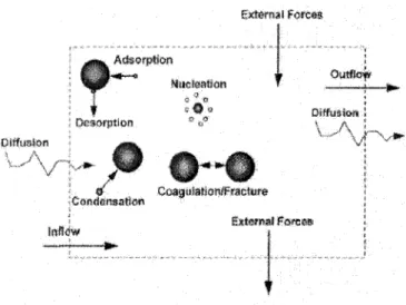
the condensation zone. In order to simulate the evaporation stage of particle, we introduce a discrete second phase which consists of spherical particles dispersed in the continuous phase. The trajectories of these discrete phase entities are computed as well as heat and mass transfer to and from them. There is a coupling between the phases and an impact on both the discrete phase trajectories and the continuous phase flow.
A s s u m p t i o n s
A summary of the main assumptions considered for the present model is summarized in table 2.2.
Table 2.2: Particle evaporation model assumptions - Particle is a sphere and fluid is an ideal gas;
- Dispersion of particles due to turbulence by stochastic tracking model; - Diluted system;
- Continuous phase with a well-defined entrance and exit conditions; - Discrete phase solved in a Lagrangian frame of reference;
- Coupling between the phases; - Particles considered as droplets;
- Thermophoretic force and Brownian motion for sub-micron particles included; - Gravity and turbulence have no influence.
The discrete phase model considers the trajectory and heat-mass transfer calculations of particles on the continuum with a coupling approach. Thus, the trajectory and heat-mass transfer calculations are based on the force balance on the particle and on the convective heat and mass transfer from the particle using the local continuous phase conditions as the particle moves through the flow.
particles. This effect is responsible that small particles in a temperature gradient are driven from the high to low temperature regions.
Equations
In the discrete phase model, the particle phase is regarded as a source of mass, momentum,
and energy to the gaseous phase. The following equations are used to calculate the set of heat and mass transfer laws involved.
Particle motion. Firstly, concerning the particle motion, the trajectory of a discrete phase
particle is predicted by integrating the force balance on the particle. This force balance equates the particle inertia with the forces acting on the particle and can be written as:
mp~TT = CD2P ( I^P ) (u - Up^u ~ UPI + Fth + mP9 + mPFb^) (2.3.1)
where u is the fluid phase velocity, mp is the particle mass, up is the particle velocity,
p is the molecular viscosity of the fluid, p is the fluid density, pv is the density of the
particle, dp is the particle diameter, Fb(t) is a Brwonian force per unit mass, and Fth is the
thermophoretic force.
The drag coefficient Co depends on the particle form and the relative Reynolds number Re, which is defined as:
Re s ^ l " " - " ! (2.3.2)
A*
equa-tions:
CD = ( j | ) /(Re) (2.3.3)
where /(Re) functions are given according to the tubulence regime by the Stokes and Oseen laws and the empirical relations proposed by [12] for the cases of particles in plasma flows.
The thermophoresis effect Fth is included in the particle force balance following the
formula by [13]. Besides, the Brownian motion Ft,(t) is considered since it becomes important for sub-micron particles. In the present study, Fb(t) is calculated as a Gaussian white noise random process [14] with spectral intensity Sn>ij given by [15]:
Sn,ij = SoSij (2.3.4)
where Sij is the Kronecker delta function, and
216vkBT
S0 = ——J— (2.3.5)
where T is the absolute temperature of the fluid, v is the kinematic viscosity, hs is the Boltzmann constant and Cc is the Stockes-Cuningham slip correction that can be computed
from:
Cc = 1 + ^ ( 1 . 2 5 7 + QAe-^u^2X^) (2.3.6)
dp
Amplitudes of the Brownian force components are of the form
where Q arc zero-mean, unit-variance-independent Gaussian random numbers.
Heat and mass transfer calculations The particle temperature is determined through
an energy balance as described in [16]. The total heat flux on a particle surface in the plasma QT is given by:
QT = fnrd2p(T - Tp) - Trd2pase(T^ - T*) (2.3.8)
where dp, h, T, Tp, as, e, Ta, pp, cp, x, Hm and H^ are the particle diameter (m),
convective heat transfer coefficient (W/m2K), local temperature of the continuous phase
(K), particle temperature, Stephan-Boltzman constant, emissivity, ambient temperature, particle density (kg/m3), heat capacity of the particle (J/kg K), molar fraction of liquid
phase, latent heat at the melting point, and boiling point, respectively.
The heat transfer coefficient, h, is evaluated using the correlation of Ranz and Marshall
Nu = | ^ = 2.0 + O.QRe'fPr1/3 (2.3.9) "'00
where fcoo is the thermal conductivity of the continuous phase (W/m — K), Re^ is the Reynolds number based on the particle diameter and the relative velocity, and Pr is the Prandtl number of the continuous phase
(cp/i/fcoo)-After heating particles, the vaporization stage is initiated when the temperature of the droplet reaches the vaporization temperature, Tvap. This stage continues until the droplets
reach the boiling point, Tbp, or until the droplet's volatile fraction is completely consumed.
The mass transfer during vaporization is predicted by a boiling rate. During droplet vapor-ization, the rate of vaporization is governed by gradient diffusion, with the flux of droplet
vapor into the gas phase related to the gradient of the vapor concentration between the droplet surface and the bulk gas:
Ni = kc(Ci,s - Cil0o) (2.3.10)
where Ni is the molar flux of vapor (kgmol/m2 s); kc is the mass transfer coefficient
(m/s); Ci>s is the vapor concentration at the droplet surface (kgmol/m3) and Cj)00 represents
the vapor concentration in the bulk gas (kgmol/m3).
The concentration of vapor at the droplet surface is evaluated by assuming that the partial vapor pressure at the interface is equal to the saturated vapor pressure, psat, at the
particle droplet temperature, Tp:
Ct,s = ^ ^ (2.3.11)
where R is the universal gas constant.
The concentration of vapor in the bulk gas is known from the solution of the transport equation for species i. The mass transfer coefficient in equation 5.3.24 is calculated from a Nusselt correlation [17]- [18]:
NuA B = - ^ = 2.0 + O.ORe^Sc1/3 (2.3.12)
where Ditin is the diffusion coefficient of vapor in the bulk (m2/s); Sc is the Schmidt
The mass of the particle is reduced according to:
mp(t + At) = mp(t) - NiApMWtiAt (2.3.13)
where MWti is the molecular weight of species i (kg/kgmol); mp is the mass of the droplet
(kg) and Ap is the surface area of the particle (m2).
2.4 The Aerosol Model
Particles of small size either in solid state or in liquid state are suspended in a gaseous medium. The suspension system is called the aerosol. Exactly speaking, aerosol means both the dispersed phase and the gaseous medium. However, in ordinary life it usually means the aerosol particles only, which have different terms in different disciplines, like "atmospheric float dust" in atmospheric science, "atmospheric condensation nuclei" in cloud physics, etc. In fact, cloud, fog and smoke, are themselves specific aerosols. We often encounter them in some atmospheric physical processes, in ordinary life, in industry, in agriculture, in some military activities, and in some scientific experiments.
The aerosol particles are very small and the disperse degree is very large. The smallest particles are of molecular scale. Several neutral molecules adhere to a charged molecule, and form a molecular aggregate. Obviously, aerosol systems are very complicated systems. There is no general recognized classification of the dispersions. According to the formation of the aerosol dispersions, they fall into two categories:
1. Dispersed aerosols: materials either in solid state or in liquid state are pulverized into granular state due to mechanical pulverization or natural weathering, then suspended in air due to the wind-force raising;
2. Condensed aerosols: the formation of the particle or the droplet is due to the conden-sation of super-saturated gas on condensed nucleus, or the particle droplet is formed in a mixture state of different gases through the photochemical reaction.
Aerosols are formed either by the conversion of gases into particulate matter or by the disintegration of liquids or solids. They may also result from the resuspension of powdered material or the break-up of agglomerates. Formation from the gas phase tends to produce much finer particles than in the disintegration process (except when condensation takes place directly on existing particles). Particles formed directly from the gas are usually smaller than 1 /iin in diameter.
In the famous book "The mechanics of aerosols" [19], Fuchs divided the aerosols into four categories:
1. Fog: aerosol dispersion in liquid state (included both dispersed and condensed sys-tems);
2. Smoke: condensed aerosol dispersion in solid state; 3. Dust: dispersed aerosol dispersion in solid state;
4. Smog: the mixture of aerosols both in solid state and in liquid state (smoke I- fog).
According to the situation, the aerosols can be divided into two categories:
1. Atmospheric aerosols: aerosols dispersed in the whole atmosphere. In fact, the whole atmosphere is an aerosol system mainly formed by natural processes, but the part formed by artificial processes has become an increasingly serious problem;
2. Industrial aerosols: aerosols formed in a factory or in a scientific laboratory. The scale is smaller than that of atmospheric aerosols. The scales of aerosols in the narrow gap of a fibre filter or an aerosol sampler are even smaller. The industrial aerosols are
usually waste material produced in industrial production. However, sometimes people manufacture particular aerosols to increase production efficiency, like various atomizer techniques and fluidized-bed techniques.
It is proper to classify aerosol according to the particle size from the view-point of the mechanics of aerosols. This is because the mechanical and other physical properties of the aerosol particles depend on the particle size. Aerosols may have several effects, including human health, climate and technological applications. Particle size, concentration, and chemical composition are usually the most important factors determining such effects.
The particle sizes of interest in aerosol behavior range from molecular clusters of 10 A to fog droplets and dust particles as large as 100 /itm. For spherical liquid droplets, the diameter {dp) is an unequivocal measure of the particle size. Spherical particles are frequently encountered in polluted atmospheres because of the growth of nuclei by condensation of liquid from the gas phase.
Particle behavior often depends on the ratio of particle size to some other characteristic length. The mechanisms of heat, mass, and momentum transfer between particles and carrier gas depend on the Knudsen number:
Kn=^ (2.4.1)
dp
where A is the mean free path of the gas. The mean free path or mean distance traveled by a molecule between successive collisions can be calculated from the kinetic theory of gases. As a good approximation for a gas composed of molecules that act like rigid elastic spheres:
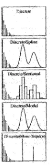
The first step in developing a numerical aerosol model is to assemble expressions for the relevant physical processes, such as chemical reactions, nucleation, condensation, coagula-tion, etc. The next step is to approximate the particle size distribution with a mathematical size distribution function. A simple scheme of this concept is shown in figure 2.1
Aerosol Model Physical process expressions (chemical reaction, nucleation, condensation, coagulation, etc.) Representation of the particle size distribution
Spline Monodisperse
Figure 2.1: Scheme of aerosol modeling
2.4.1 Review of current aerosol modeling techniques
Spline model The spline representation is so called because particle size-space is
subdi-vided into a series of contiguous sections, and the section functions are splined smoothly together at the section boundaries (Gelbard, 1978 [20]). Cubic functions are commonly used, implying that four differential equations (one for each coefficient of the cubic equation) must be solved for each section. Some examples of spline models are on the works of Middleton (1976) [21] and Gelbard and Seinfeld (1978) [22]. Although a good accuracy is observed in these models, they are computationally intensive. Moreover, solution techniques must be carefully formulated to prevent unrealistic representations of the particle size distribution.
Sectional model For the sectional technique, the size axis is divided into intervals and
the number of particles in each interval is calculated from the model. These models assume an internal mixing state of the aerosol, i.e. identical composition of particles of equal size. Because this is one of the most used models, some works related to this technique are presented below.
Kruis et al (1993) [23] presented a sectional model assuming a monodisperse aggregate and primary particle size distribution. The model was applied to an aerosol reactor describing the evolution of both primary particle and aggregate size in nonisothermal processes. In 1994, Vemury et al (1994) [24], developed a discrete sectional model using an integral lognormal distribution for calculating the self-preserving size distribution of spherical particles in the free-molecular regime. One year later, Vemury and Pratsinis [25], extended the last model to compute the evolution of nonspherical (agglomerate) particle size distributions in both the free-molecular and continuum regimes.
Jokiniemi and Pyykonen (2000) [26] presented two simplified approaches for aerosol dynamics. In the first one the shape of the size distribution is assumed and solved by the method of moments in an Eulerian reference frame. The second approach uses a sectional size distribution and does not assume an initial distribution. The results show that the final aerosol, properties of the particles exiting the reactor are well predicted by both of these models. However, as the aerosol is evolving the deposition characteristics, the sectional method becomes more accurate.
Jeong and Choi (2001) [27] presented a sectional method for the analysis of polydis-perse non-spherical particles growth subjected to coagulation and coalescence phenomena. Two sets of sectional equations that describe the evolution of particle volume and surface area, based on one-dimensional aerosol dynamics, are simultaneously solved in considering
the effect of morphological change of aggregate particles. The evolution of the aggregate particles morphology is determined from the correlation between volume and surface area concentrations of particles at each volume section.
Kim et al (2003) [28], developed a discrete-monodispersed model yielding good results and proposed the plasma reactor as a good candidate to produce monodisperse nanoparticles. In another study during the same year, Kim et al (2003) [29] simulated the generation and growth of polydisperse non-spherical silica nanoparticles in an oxy-hydrogen co-diffusion flame. They used the aggregate sectional model of Jeong and Choi (2001) [27] to solve the dynamics of particles. Non-uniform spatial distribution of flame temperatures and non-spherical particle sizes were successfully simulated.
The potential of this technique is quite large, but there are some limitations to consider. It is expensive computationally and the accuracy depends on the number of sections used to discretize the size distribution.
Modal model The modal technique has been introduced by Whitby (1990) [30] and
applied in several atmospheric models as well as reactor models; e.g. Megaridis and Dobbins (1990) [31], Whitby and Hoshino (1996) [32], Wilck and Stratman (1997) [33], etc. This technique has a flexible model structure and it is computationally fast, but the accuracy depends on the form of the mode distribution function. Compared with the sectional technique, it has the advantage that the size distribution can be characterized well with only a few number of prognostic variables.
The original modal technique was developed by Whitby (1990) [30] under the name of Modal Aerosol Dynamics Modelling (MAD). The MAD model neglects chemical particle
composition. This gap was filled later with the work of Wilck (1999) [45]. In this work an extension of the modal technique is presented as a family of models called "MADMAcS" (Multicomponent Aerosol Dynamics Modeling-Modal Approach System).
Moment model The method of moments (MOM) offers significant advantages for
incorporating aerosol processes in large-scale models. This technique is computationally very fast and accurate in tracking of integral moments, but it is only available for a limited set of processes for which a closed set of moment equations can be derived. This method emphasizes the time evolution of some moments of the size distribution rather than the size distribution itself. This is reasonable because moments (of the size distribution) are related to significant characteristic properties of the aerosol (i.e., total number, surface, and volume of particles). The self-preserving, lognormal and mul-timodal lognormal forms are the most common assumptions for the shape of the distribution.
Whitby and McMurry (1997) [35] suggest the method of moments as a suitable technique for cases in which the characteristic shape of the size distribution remains unaltered during the whole simulated process. In such cases, it is sufficient for solving the changes in the moments of the size distribution. By means of the moment methods, several models have been developed by Friedlander (1983) [37], McGraw (1984) [38], Pratsinis (1988) [39], Girshick et al. (1993) [40], Frenklach (1987) [41], Bilodeau (1996) [42] and others.
Monodisperse model Similar to the discrete representation, the monodisperse fractions
form represents the number of particles at a finite number of discrete sizes. This technique has a flexible model structure but it is useful only for rough estimate of aerosol dynamics. It does not provide information about the size distribution. More details about this technique are provided by Whitby (1990) [30].