Functional Polypyrrole Core-Shell Particles and
Flexible Membranes for Biomedical Applications
Thèse
Jifu Mao
Doctorat en Médecine Expérimentale
Philosophiae Doctor (Ph.D.)
Québec, Canada
Functional Polypyrrole Core-Shell Particles and
Flexible Membranes for Biomedical Applications
Thèse
Jifu Mao
Sous la direction de :
iii
Résumé
Le polypyrrole (PPy), l'un des polymères conducteurs de type p, a démontré un potentiel considérable dans les applications biomédicales et le stockage d'énergie en raison de sa conductivité électrique intrinsèque, sa facilité de synthèse, son potentiel de modification chimique et sa biocompatibilité. En raison de la conjugaison étendue dans ses chaînes moléculaires et de son état d'agrégation, les mauvaises propriétés mécaniques et le manque de processabilité du PPy ont été des défis scientifiques et technologiques exceptionnels. En outre, le PPy possède une bioconductivité, mais aucune bioinductivité, c'est-à-dire une absence de biofonctionnalité, ce qui constitue un autre défi pour le PPy lorsqu'il est utilisé pour des applications biomédicales. Cette thèse se concentre principalement sur ces deux défis auxquels le PPy fait face, c’est-à-dire le manque de biofonctionnalité et la mauvaise performance mécanique.
En se basant sur la différence des réactivités chimiques des comonomères, les particules de poly(pyrrole-co-(1- (2-carboxyéthyl)pyrrole structurées en noyaux-coquilles (P(Py-PyCOOH)) ont été synthétisées. Elles sont constituées d'un noyau composé d’un copolymère de P(Py-PyCOOH) riche en PPy et d'une coque composée de PPy-COOH. Les paramètres expérimentaux de polymérisation en émulsion ont été étudiés pour définir les conditions optimales. L'anticorps d’albumine de sérum humain (anHSA), en tant que molécule modèle a été immobilisé par des liaisons covalentes sur la surface des particules et a été prouvé réactif aux antigènes. Un schéma a été proposé pour illustrer la formation des particules de cœur-coquille (P(Py-PyCOOH)) selon un nouveau mécanisme basé sur les réactivités du comonomère. Cette méthode de fabrication peut permettre de préparer des particules de PPy fonctionnelles en grande quantité. La chimie de surface et de masse, la conductivité et le rendement global des particules peuvent être régulés.
Pour la première fois, une membrane en PPy souple et mécaniquement traitable (PPy-N) a été préparée par polymérisation interfaciale assistée par modèle (TIP) sans modification chimique des monomères ni autres matériaux. Les structures uniquement interconnectées et multicouches ont été considérées comme responsables de l'excellente souplesse aux températures ambiante et à -196 °C. Un mécanisme basé sur la nature exothermique de la polymérisation du pyrrole a été suggéré pour expliquer les morphologies du PPy-N. Cette
iv
membrane en PPy flexible a un poids léger (9 g m-2), une grande surface (14,5 m2 g-1), un comportement électrothermique stable, une amphiphilicité et une excellente cytocompatibilité.
Enfin, une nouvelle approche modulaire a été proposée pour immobiliser les protéines sur une surface micro/nano structurée. L'albumine de sérum bovin (BSA) et la HSA ont été immobilisées de manière covalente sur la surface des particules (P(Py-PyCOOH) avant qu’elles soient assemblées sur la surface de la membrane PPy-N pour construire une surface biofonctionnée avec la coexistence de deux types de biomolécules. Cette approche sépare la greffe de protéines et l'immobilisation en deux étapes indépendantes, fournissant ainsi une méthode simple et hautement flexible pour concevoir et fabriquer une surface ou un échafaudage multi-biofonctionnalisé.
v
Summary
Polypyrrole (PPy), one of p-type conducting polymers, has shown considerable potential in biomedical applications and energy storage owing to its inherent electrical conductivity, ease of synthesis, possibility of further chemical modification, and biocompatibility. Due to the extensive conjugation in PPy chains and the aggregation state, the poor mechanical property and processability of pristine heterocyclic PPy have been the outstanding scientific and technological challenges. Moreover, PPy only possesses bioconductivity but no bioinductivity, i.e., lack of biofunction, which is another challenge for PPy when it is applied in biomedical applications. This thesis mainly focuses on these two issues of PPy, i.e., the lack of biofunctionality and the poor mechanical performance.
Based on the difference in comonomer reactivity, the core-shell structured poly(pyrrole-co-(1-(2-carboxyethyl)pyrrole)) (P(Py-PyCOOH)) particles were synthesized, comprising the pyrrole (Py) dominated P(Py-PyCOOH) copolymer as the core and PPyCOOH homopolymer as the shell. Experimental parameters of emulsion polymerization were investigated to define the optimal conditions. Anti-human serum albumin antibody (anHSA) as a model molecule was covalently immobilized onto the particle surface and proven reactive to its antigen. A schema was proposed to illustrate the formation of the core-shell (P(Py-PyCOOH)) particles based on a new reactivity-driven mechanism. This fabrication method can be used to prepare functional PPy particles in large-scale. The surface and bulk chemistry, conductivity, and the overall yield of the particles can be regulated.
For the first time, a soft and mechanically processable PPy membrane (PPy-N) was prepared by template assisted interfacial polymerization (TIP) with neither chemical modification of the monomers nor compounding with any other materials. The uniquely interconnected and multilayered structures were considered responsible for the excellent flexibility at both room temperature and -196 °C. A mechanism based on the exothermic nature of pyrrole polymerization was suggested to explain the morphology of the PPy-N. Such a flexible PPy membrane has lightweight (9 g m-2), large surface area (14.5 m2 g-1), stable electrothermal behavior, amphiphilicity, and excellent cytocompatibility.
vi
Finally, a novel modular approach was proposed to immobilize proteins to a micro/nano structured surface. Bovine serum albumin (BSA) and HSA were covalently immobilized onto the surface of the (P(Py-PyCOOH)) particles prior to their assembly onto the surface of the PPy-N membrane, to construct a biofunctionalized surface with the coexistence of two types of biomolecules. This approach separates protein grafting and immobilization into two independent steps, providing an easy and highly flexible method to design and fabricate multi-biofunctionalized surface or scaffold.
vii
CONTENTS
Résumé ... iii
Summary ... v
List of Tables ... xiii
List of Figures ... xiv
List of Abbreviations ... xix
Acknowledgements ... xxii
Foreword ... xxv
CHAPTER IINTRODUCTION ... 1
1.1 Polypyrole (PPy)... 2
1.1.1 Intrinsically conductive polymers ... 2
1.1.2 History and chemical structure of PPy ... 3
1.1.3 Preparation methods of PPy ... 5
1.1.3.1 Electrochemical polymerization ... 5 1.1.3.2 Chemical polymerization ... 7 1.1.4 Morphology of PPys ... 10 1.1.4.1 Nanoparticles/nanocapsules... 11 1.1.4.2 Nanowires/nanofibers/nanotubes... 12 1.1.4.3 Film ... 12 1.1.4.4 Hydrogel/sponge ... 13
1.2 Potential applications of PPy and challenges ... 14
1.2.1 PPy in biomedical applications ... 14
1.2.1.1 Tissue engineering and regenerative medicine ... 15
1.2.1.2 Neural prostheses ... 16 1.2.1.3 Biosensors ... 17 1.2.1.3.1 Enzyme biosensors ... 18 1.2.1.3.2 DNA biosensors ... 18 1.2.1.3.3 Immunosensors ... 19 1.2.1.4 Drug delivery ... 20 1.2.1.5 Artificial muscle ... 21 1.2.2 Energy storage ... 22 1.2.2.1 Supercapacitors ... 22
viii
1.2.2.2 Lithium batteries ... 26
1.2.3 Electric heating elements ... 28
1.2.4 The challenges facing PPy in practical applications ... 29
1.3 Biofunctionalization of PPy... 30
1.3.1 Physical adsorption ... 31
1.3.2 Doping ... 31
1.3.3 Covalent binding immobilization ... 33
1.3.3.1 N-functionalized PPys ... 34
1.3.3.2 Poly(pyrrole-co-(1-(2-carboxyethyl)pyrrole)) ... 37
1.4 Manufacture of polypyrrole-based conducting materials ... 38
1.4.1 Polypyrrole composites ... 39 1.4.1.1 Surface coating ... 39 1.4.1.2 Particle filling ... 40 1.4.2 Micro/nanostructure design ... 42 1.5 Aims of study... 43 1.5.1 Background ... 43 1.5.2 Objectives ... 43 1.5.3 Hypotheses... 44 1.5.4 Research design ... 44
CHAPTER IISYNTHESIS AND CHARACTERIZATION OF CORE-SHELL POLY(PYRROLE-CO-(1-(2-CARBOXYETHYL)PYRROLE)) PARTICLES BASED ON A REACTIVITY-DRIVEN MECHANISM ... 45
2.1Résumé ... 47
2.2Abstract ... 48
2.3 Introduction ... 49
2.4 Results and discussion ... 51
2.4.1 Preparation of PPy-co-PPyCOOH core-shell particles ... 51
2.4.2 Different chemical compositions between core and shell ... 54
2.4.3 Conductivity of PPy-co-PPyCOOH core-shell particles ... 59
2.4.4 Grafting and activity of model antibody ... 59
2.4.5 A suggested schema for the formation of the core-shell structure ... 61
2.5 Conclusions ... 63
ix
2.6.1 Materials ... 63
2.6.2 Synthesis of functional monomer ... 63
2.6.3 Polymerization of PPy-co-PPyCOOH particles ... 64
2.6.4 Characterization ... 64
2.6.4.1 Model biomolecule grafting and detection ... 64
2.6.4.2 Morphology observation ... 65 2.6.4.3 Chemical composition ... 65 2.6.4.4 Thermostability ... 66 2.6.4.5 Conductivity measurement ... 66 2.6.4.6 Statistical analysis... 67 2.7 Acknowledgments ... 67
Notes and references ... 67
Supporting information... 70
CHAPTER IIIOPTIMIZATION OF PARAMETERS FOR SYNTHESIS OF POLY(PYRROLE-CO-(1-(2-CARBOXYETHYL) PYRROLE)) CORE-SHELL PARTICLES ... 73
3.1 Résumé ... 75
3.2 Abstract ... 76
3.3 Introduction ... 77
3.4 Results and discussion ... 79
3.4.1 The feeding of oxidant ... 79
3.4.2 The solvent systems ... 83
3.4.3 The reaction time ... 85
3.4.4 The ratio of Py/PyCOOH ... 89
3.5 Experimental ... 93
3.5.1 Materials ... 93
3.4.2 Synthesis of functional monomer ... 94
3.5.3 Polymerization of PPy-COOH particles ... 94
3.5.4 Characterization ... 95
3.5.4.1 Particle morphology ... 95
3.5.4.2 Chemical composition ... 95
3.5.4.3 Thermostability ... 95
x
3.5.4.5 Statistical analysis... 96
3.6 Conclusions ... 96
3.7 Acknowledgements ... 97
Reference ... 97
CHAPTER IVPREPARATION AND CHARACTERIZATION OF HIGHLY FLEXIBLE POLYPYRROLE MEMBRANE ... 101
4.1 Résumé ... 103
4.2 Abstract ... 104
4.3 Introduction ... 105
4.4 Results and discussion ... 107
4.5 Conclusion ... 117
4.6 Methods ... 118
4.6.1 Materials ... 118
4.6.2 Preparation of PPy membranes... 118
4.6.3 Characterizations ... 118 4.6.3.1 Morphology ... 118 4.6.3.2 Chemical composition ... 119 4.6.3.3 Tensile property ... 119 4.6.3.4 Electrical properties ... 119 4.6.3.5 Thermostability ... 120 4.6.3.6 Electrothermal behavior ... 120 4.6.3.7 Liquid adsorption ... 120
4.6.3.8 Specific surface area ... 121
4.6.3.9 Cytotoxicity ... 121 4.6.3.10 Statistical analysis... 122 4.7 Author information ... 122 4.8 Acknowledgment ... 122 4.9 Associated content ... 122 References ... 123 Supplementary materials ... 126 4.10 Supplementary text ... 127 4.10.1 Thickness ... 127 4.10.2 Absorption capacity ... 127
xi
4.10.3 A plausible mechanism of bubbles Formation ... 127
4.10.4 Conductivity ... 128
4.10.5 Three characteristics of electric heating ... 129
4.10.6 Bending of a thin-walled sheet ... 129
Reference ... 139
CHAPTER VPREPARATION AND CHARACTERIZATION OF FUNCTIONAL AND FLEXIBLE POLYPYRROLE MEMBRANE... 142
5.1 Résumé ... 144
5.2 Abstract ... 145
5.3 Introduction ... 146
5.4Experiment ... 147
5.4.1 Materials ... 147
5.4.2 Preparation of PPy membranes... 148
5.4.3 Polymerization of P(Py-PyCOOH) particles ... 148
5.4.4 Preparation of flexible and functional PPy membranes ... 149
5.4.5 Grafting of model molecules ... 149
5.4.6 Characterization ... 150
5.4.6.1 Morphology observation ... 150
5.4.6.2 Chemical composition ... 151
5.4.6.3Conductivity measurement ... 151
5.4.6.4Statistical analysis ... 151
5.5Results and discussion ... 152
5.5.1 Flexible PPy membane and P(Py-PyCOOH) core-shell particles ... 152
5.5.2Flexible and functional PPy membrane and its properties ... 154
5.5.3Grafting of model biomolecules ... 159
5.6 Conclusion ... 160
5.7 Associated content ... 161
5.8 Author information ... 161
5.9 Acknowledgement ... 161
References ... 162
CHAPTER VIGENERAL DISCUSSION AND CONCLUSIONS ... 166
6.1 General discussion ... 167
xii
6.1.2 Highly flexible PPy membrane... 169
6.1.3 Combination of functionalization and flexibility for PPy ... 171
6.1.4 Grafting biomolecules onto particles surface ... 172
6.2 General conclusions ... 173
6.3 Limitations and perspectives ... 174
REFERENCES ... 175
xiii
List of Tables
Table 1.1 Performance of PPy-based elecrodes for supercapacitors ... 25
Table 1.2 Biomedical applications of PPyCOOH... 37
Table 2.1 Surface elements analysis by XPS (Atomic %) ... 55
Table 2.2 Total elements analysis (mass %) ... 56
Table 3.1 Surface chemical composition, conductivity, and the yield of the P(Py-PyCOOH50) particles in different reaction time ... 87
Table S4.1Properties of PPy membranes prepared by interfacial polymerization. ... 131
xiv
List of Figures
Figure 1.1 Chemical structures of some common conducting polymers . ... 3 Figure 1.2 Neutral, polaron and biopolaron chemical structures of PPy. +: charge; •:
unpaired electron; A-: dopant. ... 4
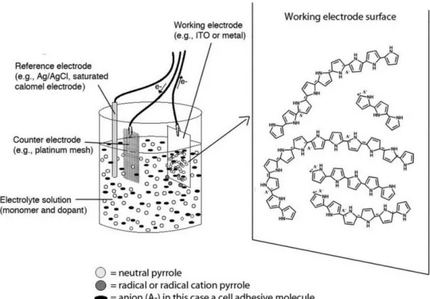
Figure 1.3 Three-electrode system for electrochemical polymerization: reference, working,
and counter electrodes submersed in a monomer and electrolyte solution. ... 5
Figure 1.4 Scheme of the electrochemical (chemical) polymerization mechanism of PPy. 6 Figure 1.5 A stoichiometric chemical polymerization of PPy with ferric chloride oxidant .
... 9
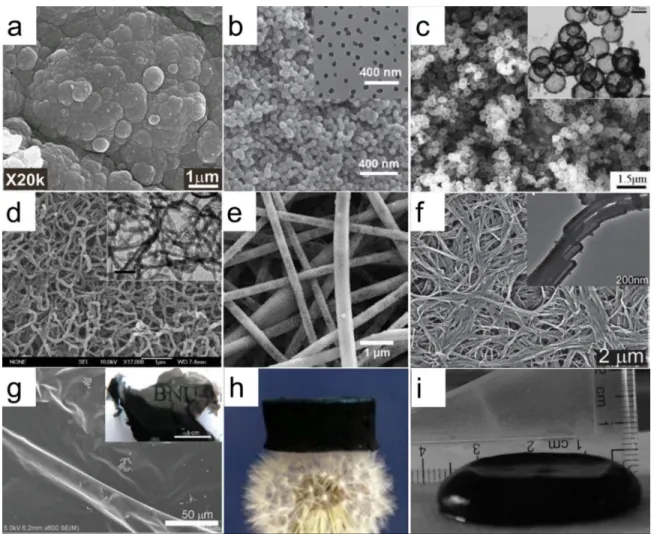
Figure 1.6 Morphology of PPys: a, cauliflower-like particles; b, nanoparticles; c,
nanocapsules; d, nanowires; e, nanofibers; f, nanotubes; g, film; h, sponge; I, hydrogel. ... 10
Figure 1.7 PPy serving as a conducting biointerface for various biomedical applications .
... 14
Figure 1.8 Schematic of a biosensor. The sensing element (e.g., biomacromolecule) detects
the analyte, and then a series of signal will be produced and monitored by electronic device. ... 17
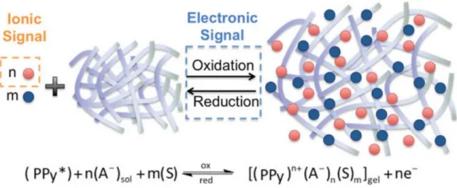
Figure 1.9 The oxidation-reduction reaction of PPy in solution . A- : an anionic dopant (red
dots); S: solvent molecule (blue dots). ... 20
Figure 1.10 Scheme of a bilayer device: (a) conducting polymer film adhered to a
non-conductive tape; (b) Anticlockwise movements during oxidation; and (c) clockwise movements during reduction. ... 21
Figure 1.11 A schematic illustration of the working principles of lithium-ion battery . ... 27 Figure 1.12 A schematic illustration of functionalization of PPy by biomolecules via (a)
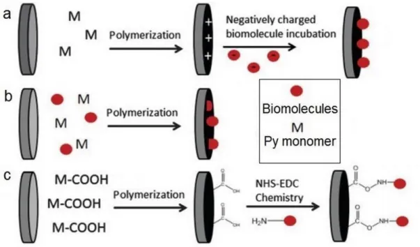
physical adsorption; (b) doping; (c) covalent binding. ... 30
Figure 1.13 Chemical structures of carboxylic acid-functionalized Py monomers: (a)
N-position substituted 1-(2-carboxyethyl)pyrrole; (b) α-N-position substituted pyrrole-2-carboxylic acid; (c) β-position substituted pyrrole-3-carboxylic acid. ... 33
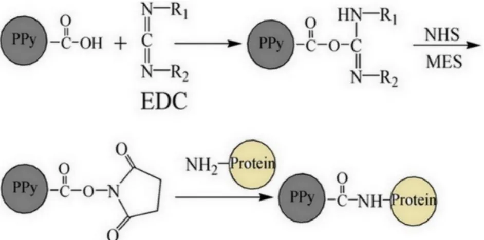
Figure 1.14 Schematic representation of grafting biomolecules onto PPy-NHS , showing
the yield and the characteristic absorptions of carboxyl groups. ... 36
Figure 1.15 Schematic representation of grafting biomolecules onto PPyCOOH based
PPy-NHS using PPy-NHS-EDC coupling ... 36
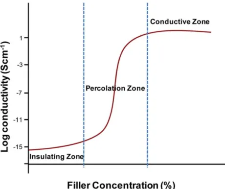
Figure 1.16 Conductivity of polymer composites as function of PPy filler concentration.
... 41
xv
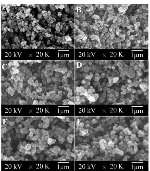
Figure 2.1 SEM photomicrographs of PPy-co-PPyCOOH particles prepared in different
reaction times from 10 min to 24 hours: (A) 10 min, (B) 40 min, (C) 1.5 h, (D) 6 h, (E) 12 h, and (F) 24 h. ... 51
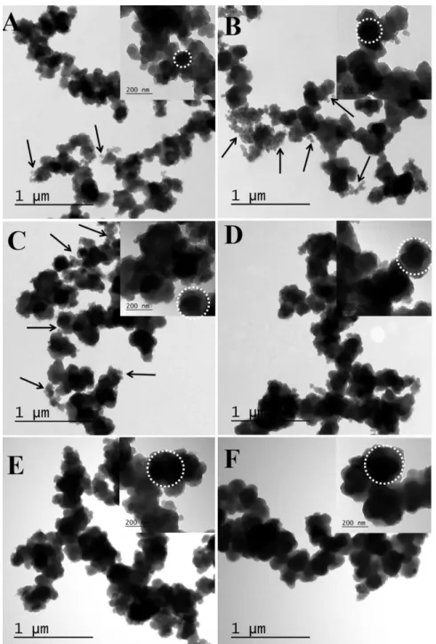
Figure 2.2 TEM photomicrographs of PPy-co-PPyCOOH particles prepared in different
reaction times from 10 min to 24 hours: (A) 10 min, (B) 40 min, (C) 1.5 h, (D) 6 h, (E) 12 h, and (F) 24 h. ... 52
Figure 2.3 The FTIR spectra (A), TG and DTG analyses (B), and the yield and conductivity
(C) of the PPy-co-PPyCOOH particles synthesized at different reaction times from 10 min to 24 h. ... 53
Figure 2.4 High resolution XPS spectra of C1s (A), N1s (B) and O1s (C) of the
PPy-co-PPyCOOH particles synthesized at different reaction times ranging from 10 min to 24 h. D to F are the representative curve fittings for the particles harvested at 18 h. ... 57
Figure 2.5 TEM photomicrographs of PPy homopolymer (upper panel) and
PPy-co-PPyCOOH copolymer (lower panel) synthesized at different reaction times from 10 min to 40 min: (A) and (D) 10 min, (B) and (E) 20 min, (C) and (F) 40 min. ... 58
Figure 2.6 SEM photomicrographs of the PPy-co-PPyCOOH coated membrane (A) and
fluorescence photomicrographs of protein immobilization (B, C). A1: cross-section showing a layer of particles on a PLA substrate; A2: morphology of the particulate surface; B1: Anti-HSA (FITC, green) grafted surface showing successful immobilization of the antibodies; B2: B1 incubated in HSA (rhodamine, red) showing the functionality of the immobilized antibodies; C1: BSA grafted surface showing no fluorescence; and C2: C1 incubated in HSA (rhodamine) showing little nonspecific absorption of HSA (rhodamine). ... 60
Figure 2.7 A five-step schema to explain the formation of the core-shell structured
PPy-co-PPyCOOH particles. The quickly formed framework is made of the aggregation of the PPy dominated copolymer cores, which are gradually surrounded and finally wrapped by a shell made of the PPyCOOH homopolymer nanoparticles. ... 61
Figure S2.1 1H NMR (400 MHz, CDCl3) result of 1-(2-Carboxyethyl)pyrrole. ... 71
Figure S2.2 13C NMR (100 MHz, CDCl3) result of 1-(2-Carboxyethyl)pyrrole. ... 71
Figure S2.3 FTIR spectra of 1-(2-Carboxyethyl)pyrrole and 1-(2-cyanoethyl)pyrrole. .... 72 Figure S2.4 SEM photomicrographs and XPS spectra of PPy-COOH polymer obtained
from filtrate of reaction for 12h: (A-B) SEM photos, (C) Full XPS spectra. .. 72
Figure 3.1 SEM photomicrographs of P(Py-PyCOOH50) copolymers synthesized with
different feedings of Fe3+ (100 mL solution; Py/PyCOOH=50/50, 15 mmol; H2O/CHCl3= 30/70; reaction for 24 h): (A) 35 mmol; (B) 50 mmol; (C) 70
mmol; (D)80 mmol; (E) 90 mmol ; (F) 130 mmol. ... 80
Figure 3.2 Properties of the P(Py-PyCOOH50) copolymers synthesized with different
xvi
30/70; reaction for 24 h). (A): FTIR spectra; (B): Full XPS spectra; (C): C1S
core level spectra; (D): TGA thermograms; (E): The overall yield; and (I): Surface conductivity. ... 81
Figure 3.3 Effect of W/O ratio on copolymer properties (100 mL solution; 80 mmol Fe3+;
Py/PyCOOH=50/50, 15 mmol; reaction for 24 h): (A-D) SEM photos: (A) 20/80; (B) 25/75; (C) 30/70; (D) 40/60; (E) FTIR spectra; (F) Full XPS spectra; (G) C1S core level spectra; (H) Conductivity; and (I) Overall yield. ... 84
Figure 3.4 SEM photomicrographs of P(Py-PyCOOH50) particles synthesized in different
reaction times from 10 min to 24 h (100 mL solution; 80 mmol Fe3+;
Py/PyCOOH=50/50, 15 mmol; H2O/CHCl3= 25/75): (A) 10 min, (B) 20 min,
(C) 40 min, (D)1 h, (E) 1.5 h , (F)6 h, (G) 12 h, (H) 18 h, and (I) 24 h. ... 85
Figure 3.5 FTIR spectra (A), XPS spectra (B), and elements analyses (C) of the
P(Py-PyCOOH50) copolymers synthesized in different reaction times from 10 min to
24 h (100 mL solution; 80 mmol Fe3+; Py/PyCOOH=50/50, 15 mmol; H2O/CHCl3= 25/75). The dash lines in C represent the theoretical values of the
corresponding structures. ... 86
Figure 3.6 TEM photomicrographs of P(Py-PyCOOH50) copolymers synthesized in
different reaction times from 10 min to 24 h (100 mL solution; 80 mmol Fe3+; Py/PyCOOH=50, 15 mmol; H2O/CHCl3= 25/75): (A) 10 min, (B) 20 min, (C)
40 min, (D)1 h, (E) 1.5 h , (F) 6 h, (G) 12 h, (H) 18 h, and (I) 24 h. ... 89
Figure 3.7 SEM photomicrographs of the P(Py-PyCOOH) polymers synthesized with
different ratios of Py/PyCOOH (100 mL solution; 80 mmol Fe3+; H2O/CHCl3=
25/75; 18 h): (A) 100:0, (B) 75:25, (C) 50:50, (D) 25:75, (E) 0:100. ... 90
Figure 3.8 Properties of the P(Py-PyCOOH) particles synthesized with different ratios of
Py/PyCOOH (100 mL solution; 80 mmol Fe3+; H2O/CHCl3= 25/75; 18 h): (A)
FTIR spectra, (B) TGA thermograms, (C) conductivity, (D) XPS survey scans, (E) C1s core level spectra, and (F) ratio of N1s+/N1s based on curve fitting of the
N1s core level spectra. ... 93
Figure 3.9 Chemical reaction scheme of the synthesis of P(Py-PyCOOH) copolymers. .. 94 Figure 4.1 Diagram of the template-assisted interfacial polymerization (TIP) of a flexible
PPy membrane (PPy-N). (A) Beginning of TIP, showing the enrichment of the nanorod templates. (B) End of TIP, showing a black product near the interface. (C) Final PPy-N membrane obtained after washing and drying. (D) Nanorod template structure formed by FeCl3 and MO. (E) MO@PPy nanorod structure on the water side of the membrane. (F) PPy nanotube structure following removal of templates. (G) MO and PPy molecular structure. (H) Bubbles on the chloroform side. (I) Final PPy-N membrane is flexible both at room temperature and in liquid nitrogen, showing PPy bubbles. ... 107
Figure 4.2 Morphology of PPy-N and PPy-P synthesized at 4 °C. (A-C) Scanning electron
microscopy (SEM) photos of PPy-N. (A) Large intact and burst bubbles formed in the chloroform phase; insert shows their dense surface. (B) Cross section at low and high (insert) magnifications, showing the multilayer structure and thin solid membrane. (C) Nanotube side formed in the water phase. (D-F) SEM
xvii
photos of PPy-P. (D) Small intact and burst bubbles formed in the chloroform phase; insert shows the porous bubble surface. (E) Cross section at low and high (insert) magnifications, showing the thick layer of PPy particles and thin solid membrane. (F) Particle side formed in the water phase. (G-I) Transmission electron microscopy (TEM) photos of PPy nanotubes and particles. (G) PPy nanotubes removed from PPy-N. (H) High magnification of (G). (I) PPy particles removed from the PPy-P. ... 109
Figure 4.3 Formation of the flexible PPy-N and PPy-P membranes. ... 110 Figure 4.4 Physical properties and processability of PPy-N. (A) An as-prepared membrane
15 cm in diameter. (B) Cutout. (C) Cyclic bending at room temperature (7.5 cm × 2.5 cm). (D) Waving in liquid nitrogen (7.5 cm × 1.0 cm). (E) Tie and cube. (F) Rolling and laminating. (G) Radial elasticity of a triple-layer tube. (H) Stress-strain curves of PPy-N vs. PPy-P (5.0 cm × 1.0 cm). Insert: Section following tensile fracture. (I) Current-time curve of a 7.5 cm × 2.5 cm strip bent to different curvatures under 2.0 V. ... 112
Figure 4.5 Ohmic and electrothermal behavior of PPy-N. (A) Current-voltage (I-V) curves
at room temperature. (B) Current-voltage (I-V) curves in liquid nitrogen. (C) Membrane surface temperature (Tmax) vs. voltage. Insert: Infrared thermal images of the membrane surface at specific voltages (red dot circles). (D) Time-dependent surface temperature changes at various voltages. ... 115
Figure S4.1 Photographs taken at 10 minutes after polymerization. (A) Without the MO
template. (B) With the MO template (TIP). (A and B) Side view. (A1 and B1) Top view. (A2 and B2) Bottom view. ... 132
Figure S4.2 Photographs taken after polymerization. (A) Without the MO template. (b)
With the MO template (TIP). (A and B) Side view. (A1 and B1) Top view. (A2 and B2) Bottom view. ... 133
Figure S4.3 Appearance and growth of the bubbles at the chloroform side of the PPy-N
membrane synthesized at 22℃. ... 134
Figure S4.4 Scanning electron microscopy photomicrographs of PPy-N and PPy-P
membrane synthesis at -20 ℃. (A-C) PPy-N. (A) Bubble side. (B) Cross section. (C) Nanotube side. (D-F) PPy-P. (D) Bubble side. (E) Cross section. (F) Particle side. (A-F) Inset: High magnification... 134
Figure S4.5 Scanning electron microscopy photomicrographs of PPy-N and PPy-P
membrane synthesis at 22 ℃. (A-C) PPy-N. (A) Bubble side. (B) Cross section. (C) Nanotube side. (D-F) PPy-P. (D) Bubble side. (E) Cross section. (F) Particle side. (A-F) Inset: High magnification. ... 135
Figure S4.6 Chemical and thermal properties of PPy-N and PPy-P. (A) Attenuated total
reflectance Fourier transform infrared spectroscopy (ATR-FTIR) spectra. (B) Full scans of X-ray photoelectron spectroscopy (XPS). (C) Thermograms of thermogravimetric analysis (TGA). PPy-N-O: side of PPy-N facing the chloroform; PPy-P-O: side of PPy-P facing the chloroform; PPy-N-W: side of PPy-N facing the water; PPy-P-W: side of PPy-P facing the water. ... 136
xviii
Figure S4.7 Stability of the PPy-N, PPy-P, and PPy nanotube-cast membranes under
ultrasound treatment. (A) Before ultrasound treatment. (B) After 30 min of ultrasound treatment. ... 137
Figure S4.8 Illustration of the bending of a thin-walled plate. R: radius of curvature; θ:
radian of curvature; L: length of neutral line; ∆L: change in length of the external layer; a: thickness of the plate. ... 138
Figure S4.9 Attachment and growth of human skin fibroblasts on PPy-N. Left panel (1-3):
Cell nuclei stained with Hoechst fluorescent dye. Right panel (4): Quantification of cell membrane proteins (Bradford assay) as an indication of cell numbers. ** p < 0.01, n ≥ 4. ... 138
Figure 5.1 Diagram of entrapping the model protein grafted P(Py-PyCOOH) particles onto
the nanotube side of the flexible PPy membrane. ... 150
Figure 5.2 Morphology of flexible PPy membrane and core-shell P(Py-PyCOOH)
particles: a-c, SEM photos of PPy membrane: a, Nanotube side formed in water phase at low and high (insert) magnifications; b, Cross-section of the membrane; c, Intact and burst large bubbles formed in oil phase. d, SEM photos of P(Py-PyCOOH) particles at low and high (insert) magnifications. e-f, TEM photos of PPy membrane and particles: e, PPy nanotubes removed from the PPy membrane; f, P(Py-PyCOOH) particles. ... 153
Figure 5. 3 The conductivity and gross observation (a), the residual percentage (PR)
and weight ratio of particles (PF) (b), and the FTIR spectra of the
P(Py-PyCOOH) particles and the PPy membranes immobilized with varying amount of particles. ... 155
Figure 5.4 SEM photomicrographs of the P(Py-PyCOOH) particle immobilized
flexible PPy membranes at different particle feeding ratios: (a) 0.05 mg cm-2, (b) 0.11 mg cm-2, (c) 0.27mg cm-2, (d) 0.53 mg cm-2, (e) 1.07 mg cm-2, (f) the bubble side of the membrane loaded with 1.07 mg cm-2 particles. ... 156
Figure 5.5 The processability and flexibility of the P(Py-PyCOOH) particle
immobilized flexible membranes: (a) functionalized PPy tubes, (b) cyclic fold in longitudinal direction, (c) cyclic fold in latitudinal direction, (d) radial compression recovery of PPy tube. ... 157
Figure 5.6 Fluorescent photomicrographs of protein immobilization: (a-c) BSA
(FITC, green) grafted surface, (d-f) HSA (Rhodamine, red) grafted surface, (g-i) BSA and HSA grafted surface. (a, d, g) observation of fluorescein FITC, (b, e, h) observation of Rhodamine red , (c) merge of (a) and (b), (f) merge of (d) and (e), (i) merge of (g) and (h). ... 159
xix
List of Abbreviations
anti-HSA Human serum albumin antibody ATP Adenosine triphosphate
BC Bacterial cellulose
BET Brunner-Emmet-Teller Measurement BSA Bovine serum albumin
CNF Carbon nanofiber CNT Carbon nanotube Col Collagen
CP Conducting polymer CS Chondroitin sulphate
DBS Dodecylbenzenesulfonic acid sodium salt DEHS Di(2-ethylhexyl) sulfosuccinate
DMEM Dulbecco's modified Eagle's medium DS Dextran sulphate
dsDNA Double stranded DNA
DTG Derivative thermogravimetric analysis ECM Extracellular matrix
ECP Electrically conducting polymer
EDC N-(3-Dimethylaminopropyl)-N′-ethylcarbodiimide hydrochloride EDLC Electric double layer supercapacitor
EIS Electrochemical impedance spectroscopy EO Ethylene oxide
EP Electrochemical polymerization
FTIR Fourier transform infrared spectroscopy GOD Glucose oxidase
GOx Glucose oxidase HA Hyaluronic acid
HCG Human chorionic gonadotropin HE Heparin
xx IC Indigo carmine
ICP Intrinsically conductive polymer LDH Layered double hydroxides LIB Lithium-ion battery
MO Methyl orange
NGC Nerve guidance conduit NGF Nerve growth factor NHS N-Hydroxysuccinimide NMP N-methylphenothiazine NMR Nuclear Magnetic Resonance
P(Py-PyCOOH) or PPy-co-PPyCOOH Poly(pyrrole-co-(1-(2-carboxyethyl)pyrrole)) PA Polyacetylene
PAN Polyacrylonitrile PANI Polyaniline
PBS Phosphate buffered saline PC Polycarbazole
PCL Polycaprolactone PDLLA Poly (D,L-lactide)
PEDOT Poly(3,4-ethylenedioxythiophene) PEG Polyethylene glycol
PET Poly(ethylene terephthalate) PF Polyfluorene
PI Polyindole PLA Polylactic acid
PLGA Poly(lactic-co-glycolic acid)
PMAS Poly(2-methoxyaniline-5-sulfonic acid) PPP Polyphenylene
PPV Poly(phenylene-vinylene) PPy Polypyrrole
PPyCOOH Poly(1-(2-carboxyethyl)pyrrole)) PPy-N Flexible PPy membrane with nanotubes
xxi
PPy-NH2 Poly (pyrrole-co-N-3-aminopropylpyrrole)
PPy-NHS Poly(pyrrole-co-succinimidyl pyrrole) PPy-P PPy membrane with particles
PPy-PO Poly(pyrrole-co-N-glycidylpyrrole) PS Polystyrene PSS Poly(styrenesulfonate) PTH Polythiophene pTS Para-toluenesulfonic acid PU Polyurethane
PVA Polyvinyl alcohol
PyCN or Py-CN N-(2-cyanoethyl)pyrrole PyCOOH or Py-COOH 1-(2-carboxyethyl)pyrrole PyNH2 or Py-NH2 N-3-aminopropylpyrrole
PyOH or Py-OH 2-(1H-Pyrrol-1-yl)ethanol PyPO or Py-PO N-glycidylpyrrole
RGD Arg-Gly-Asp
rGO Reduced graphene oxide SEM Scanning electron microscopy ssDNA Single stranded DNA
TEM Transmission electron microscopy Tg Glass transition temperature TGA Thermal gravity analysis
TIP Template assisted interfacial polymerization XPS X-ray photoelectron spectroscopy
xxii
Acknowledgements
To achieve one of my dreams and great objectives, I came from as far as oriental China to defend a PhD at Université Laval, Canada, nearly 5 years ago. While I owned nothing when I came here and I still do now, the delightful experience of studies and life in Québec makes me have strong mental qualities and knowledge to meet the next phase of my life. Although being a personal achievement, such an honor and a privilege cannot be accomplished without countless academic, educational and psychological help, encouragement and supports from many special people surrounding me.
First of all, I would like to express my deepest appreciation and thanks to Prof. Ze Zhang for inviting me to join his research group, for bringing me into the field of conductive polymers, and for the continuous and patient guidance in my research. As an eminent scientist, Ze inspired me and provided me numerous valuable suggestions on my research and paper writing. My gratitude is also extended to a great deal of freedom on my research that he gave me, as well as the encouragement and trust. Furthermore, Ze always encourages and supports financially me to attend the academic conferences to keep up to date with new developments of biomaterials and to improve my social and communicative competence. Here, I would also like to thank Madam Jin Yang for inviting me to join the family parties during Spring Festival that gave me a home feeling in Québec City.
I would also like to address my sincere thanks to Prof. Robert Guidoin for offering an opportunity to join his project on artificial heart valve and stent graft. He helps me deeply understand from basic research of biomaterials to clinical applications of medical device. His perpetual energy and enthusiasm on academic research shall inspire my future research life. I am grateful to Prof. Mahmoud Rouabhia from faculty of dentistry of Université Laval, Prof. Xingyi Xie from Sichuan University, and Prof. Shiyun Meng from Chongqing Technology and Business University for their valuable discussions and suggestions.
I also wish to thank all my colleagues for their friendship and great help: Dr. Hyun Jin Park and Dr. Yongliang Wang contributed to the work of cell culture involved in my thesis; Dr. Bin Li, Dr. Olexandr Bondarenko, Madam Dingkun Wang, and Mr. Zhiyong Du provided generous discussions on immunology; Madam Yiwei Tong helped to prepare attractive
xxiii
graphic abstracts and polish manuscripts; Madam Chaojing Li assisted with mechanical measurements and analysis; Dr. Yingchao Su and Madam Mahrokh Dorri taught me how to perform electrochemical impedance spectroscopy test and analysis. And I am also very gratefully for the technical assistances from Dr. Stéphane Turgeon, Dr. Pascale Chevallier, Dr. Sébastien Meghezi, and Madam Andrée-Anne Guay-Bégin. The help from Dr. Xu Dong on BET (Brunauer-Emmett-Teller mearsurement) surface area measurement is also greatly appreciated.
I highly appreciate the financial support from the Natural Sciences and Engineering Research Council of Canada (NSERC), the Canadian Institutes of Health Research (CIHR), and scholarships from Medicine Faculty of Université Laval and from Fondation du CHU de Québec.
My thanks and wishes are also extended to my close Chinese friends in Université Laval and the exchange students from Shanghai Jiao Tong University and Sichuan University for their helpc encouragement, and support.
Special thanks to my parents, godmother, younger brother, and relatives for their continuous love and support throughout my life. Every Sunday, telephone calls and video chats through internet made me feel the warmth of my family. In particular, I would like to express gratitude to my godmother Madam Ximeng Zhang for guiding me with a positive attitude towards life, love and career.
xxiv
To my parents, Guixia Gao and Chuanwen Mao
To my godmother, Ximeng Zhang
To my brother, Jicai Mao
《
Heaven helps those who help themselves
》
xxv
Foreword
This PhD thesis contains six chapters, including four scientific articles (Chapter II to V) that either have been published, submitted or to be submitted. The research work was conducted in the Centre de Recherche du CHU de Québec located in l’Hôpital Saint-François d'Assise. Chapter I reviews the background knowledge related to the research project, including the preparation and properties of PPy, its potential applications and challenges, and how to biofunctionalize and manufacture PPy-based materials. The hypotheses and objectives of the thesis are presented at the end of this chapter.
Chapter II reveals a novel reactivity-driven mechanism in the synthesis of the core-shell structured conductive polymer particles. The reactions are based on the difference in comonomer reactivity via a simple one-step and one-pot emulsion polymerization. Chapter II was published in J. Mater. Chem. B, 2016, 4, 5429-5436 authored by Jifu Mao and Prof. Ze Zhang. Jifu Mao: experiments and manuscript writing; Prof. Ze Zhang: supervision of the experiments, revision of the manuscript and the financial support.
Chapter III demonstrates the optimization of experimental parameters in the one step emulsion polymerization of the functional PPy particles, including the ratio of water/oil, feeding of FeCl3 and functional monomers, as well as reaction time, based on a balance in
the quantity of carboxyl groups on particles surface, conductivity and overall yield. This part of the work has been published in Polymer 2016,105,113-123 authored by Jifu Mao and Prof. Ze Zhang. Jifu Mao: experiments and manuscript writing; Prof. Ze Zhang: supervision of the experiments, revision of the manuscript and the financial support.
Chapter IV presents a new approach named template assisted interfacial polymerization that was used to prepare a mechanically processable pristine PPy membrane possessing a remarkable softness and flexibility even in liquid nitrogen, despite the fact that the glass transition temperature of PPy is above 100 oC. Jifu Mao: experiments and manuscript writing; Prof. Ze Zhang: supervision of the experiments, revision of the manuscript and the financial support; Madam Chaojing Li: mechanical measurements and analysis; Dr. Hyun Jin Park: cell culture; Prof. Mahmoud Rouabhia: providing useful suggestions and discussion on the
xxvi
results. This research has been published in ACS Nano 2017 (DOI: 10.1021/acsnano.7b05546).
Chapter V reports a straightforward strategy to prepare a functional and flexible electrically conducting PPy membrane, taking the advantages of the topology of nanotubes on the PPy membrane and the pea-like structure of the P(Py-PyCOOH) particles. This work is to be submitted to a scientific peer reviewed journal.
Finally, Chapter VI presents the general discussion, general conclusion and also the perspectives.
1
CHAPTER I
2
1.1 Polypyrole (PPy)
1.1.1 Intrinsically conductive polymers
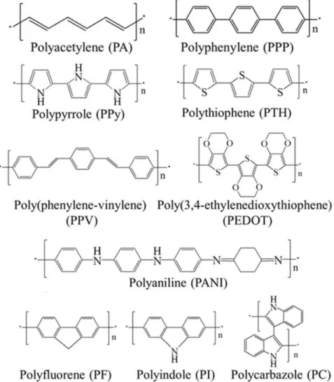
Intrinsically conductive polymers (ICPs), also known as conducting polymers (CPs) or electrically conducting polymers (ECPs), are conjugated polymers possessing unique electrical conductivity, electron affinity, and redox activity, which are different from carbon-based and metal filler-carbon-based conductive polymeric composites. The backbone of CPs always consists of π-conjugated chains allowing unpaired electrons delocalizing along the polymer chain, which is one of the basic requirements for CPs 1. Another requirement is doping treatment which was systematically investigated in 1970s 2. Following the accidental discovery of the silvery polyacetylene (PA), Heeger, Macdiarmid and Shirakawa cooperatively indicated that after a doping process, the conductivity of PA membrane was increased remarkably to 103 S cm-1, an increase of around 8 orders of magnitude 2, for which they were awarded the Chemistry Nobel Prize in 2000. Since the discovery of doping, numerous CPs of high conductivity were synthesized successively 1, 3, 4, such as PPy, polyphenylene, polythiophene, poly(3,4-ethylenedioxythiophene), poly(phenylene-vinylene), and polyaniline. Their chemical structures are shown in Figure 1.1.
For an overwhelming majority of CPs, a treatment with suitable dopants can make them remarkably conductive. A neutral CPs can be p-doped with anions (oxidizing) or n-doped with cations (reducing). The dopants not only neutralize and stabilize the positive charges of the oxidized polymer backbone, but more importantly also delocalize the valence electrons to prompt the charge flux through the polymer upon an electrical potential applied to the polymer 5. That is, the doping process introduces charge carriers moving along the backbone
of CPs to generate electrical conductivity. The conductivity of CPs depends on the energy of the band gap, which is the distance between conducting band and valence band. The smaller band gap energy is, the better conductivity is considered to be. Band gap is affected mainly by the nature of dopant, doping level, synthesis method and temperature 6. For example, the band gap of PPy decreases with the increasing of doping level 7. Among all CPs, because of its superiority in conductivity, ease of synthesis, chemical stability and biocompatibility, PPy
3
has been in the focus of investigations, particularly for biomedical applications, energy storage, antistatic, and electric heating elements 8-11.
Figure 1.1 Chemical structures of some common conducting polymers 3.
1.1.2 History and chemical structure of PPy
Though the preparation of PPy could date back to early 1910s, the electrically conducting PPy was first discovered and reported only in the early 1960s 12, while the significantly conductive PPy had not been studied extensively until the electrochemistry method became employed in 1980s 13. As shown in Figure 1.1, the ideal chemical structure of PPy was formed by a number of pyrrole rings repeatedly connected through the carbon at α position of the monomers. However, linear molecules formed by α-α linkages can only be achieved at the beginning of the polymerization. With the growth of a PPy molecule, the activation of β sites allows different arrangement of pyrrole rings, thus forming a three-dimensional (3D)
cross-4
linked network. Moreover, the insertion of dopants and the distortion of chains will lead to different inclinations such as cones or helices 14. Highly cross-linked structures reduce the conjugation length, electrical conductivity, and solubility of PPy. Therefore, it is generally known that PPy is very difficult to further process once synthesized, presenting non-thermoplastic, mechanically rigid, brittle and insoluble characteristics 15. In general, the heterogeneity of PPy structure due to the nonlinear polymerization makes it inferior in conductivity, mechanical properties and processability. Because of this, instead of being used as a single component, PPy has to be composed with other types of materials to form composites (in form of filler, coating, or suspension).
Figure 1.2 Neutral, polaron and biopolaron chemical structures of PPy. +: charge; •: unpaired
electron; A-: dopant.
Because the backbone of the oxidized PPy is positively charged 16, understandably, it is necessary for conducting PPy to possess suitable anionic counterions. Previous studies have concluded that, depending on the level of oxidation, conduction via polarons or bipolarons (Fig. 1.2) is the dominant mechanism of charge transport in PPy 8, 16. Bipolaron is generated
either by the further oxidation and removal of the unpaired electron in polaron, or by the union of two independent polarons between the adjacent chains through a charge transfer reaction. Comparing to polarons, bipolarons are more favorable to transfer along the PPy chains and are considered the dominant charge carrier. Based on the doping ratio of nitrogen
5
in pyrrole rings, oxidized PPy normally has one charge for every three or four pyrrole repeating units 17. Noticeably, the morphology and properties of PPy are inextricably linked to its synthesis methods, generally including electropolymerization and chemical polymerization.
1.1.3 Preparation methods of PPy
1.1.3.1 Electrochemical polymerization
Figure 1.3 Three-electrode system for electrochemical polymerization: reference, working,
and counter electrodes submersed in a monomer and electrolyte solution8, 18.
Although PPy was first synthesized through chemical oxidation, the first well recognized conductive PPy film (100 S cm-1) was prepared by Diaz via electro-oxidation on a platinum electrode in acetonitrile at 1979 19. This historic finding opened the prologue of research on CPs using EP. As shown in Fig. 1.3, PPy prepared through EP is in the form of a film on the working electrode of a three-electrode configuration (working, counter, and reference electrodes), which usually shows a uniform structure and high conductivity. In the solution, there are Py monomer, solvent, and electrolyte (dopant) 8. Various modes of EP were
6
developed to synthesize PPy including potentiostatic (constant potential), galvanostatic (constant current), and potentiodynamic (potential scanning, i.e. cyclic voltammetry) 20, 21. The main advantages of EP lie on 16, 22: a). The product is an electroactive film with high conductivity; b). The product is generally obtained in the doped state after synthesis. For example, biological molecules can be used as dopant and directly incorporated into polymer during polymerization; c). The mass and thickness of the film can be controlled by the total charge via regulating potential/current and polymerization time; d). The in situ coating of PPy on complex substrate is particularly useful for preparing sensors. Though various mechanisms have been proposed to explain the mechanism of EP, two of them received the greatest attention, that is, the oxidative coupling of monomer molecules23 and the free radical
reaction24.
Figure 1.4 Scheme of the electrochemical (chemical) polymerization mechanism of PPy23,
7
For now, a pseudo-polycondensation mechanism presented by Diaz 23 is most commonly accepted in the literature, which is considered appropriate for both EP and chemical polymerization of PPy. There are 7 steps in this mechanism 23, 25, 26, as shown in Fig.1.4, including the formation of a cation radical monomer, coupling between two radicals, loss of two protons to form an aromatic dimer, oxidation of the dimer to form a cation radical, coupling between the radical dimer themselves or with an active monomer, and the propagation that continues via the same sequence till termination. Termination happens when no further monomer left or side reactions terminate the propagation 27.
In conventional EP of PPy, the monomers were oxidized at the working electrode surface forming an insoluble and thin polymer film. The morphology and properties of the PPy film depend on a number of variables including the nature of the solvent, pH, temperature, electrolyte, electrode system, the purity and the concentration of monomer, and deposition time and charge 8, 22. Stripping the PPy film off the working electrode is not always feasible because of the strong adhesion and the brittleness of the PPy film that is normally only several micrometers in thickness. Meanwhile, the area of the film totally depends on the size of the substrate or electrode, which is one of the main restrictions. To produce large films, a free-standing PPy film was generated at the air/liquid interface through EP 28. Li also electrochemically synthesized free-standing PPy film at the three-phase interline, and evaluated the effect of potential, counterion and pyrrole concentration 29. However, the disadvantages of EP lie in the low productivity, high cost, and specialized equipment, and the requirement for the carefully processed electrode and high-purity chemicals. Therefore EP is a more promising method to prepare electronic devices and sensors.
1.1.3.2 Chemical polymerization
Chemical polymerization is one of the first and still the most widely used approach for the preparation of PPy. Due to its solubility and the low oxidation potential that is less than 0.8V, pyrrole is vulnerable to oxidation and so can be synthesized chemically in a series of aqueous and non-aqueous solvents 30. The chemical polymerization of PPy takes place when pyrrole
meets the oxidant in a solvent according to the mechanism illustrated in Fig. 1.4, in which monomer oxidation is realized by the oxidant instead of oxidative electrical potential. In general, in solution polymerization, PPy precipitates as insoluble matter in forms of either
8
the deposition on the surface of various substrates or homogeneous powder. Compared to EP, chemical synthesis is preferred when a large quantity of CPs is required, which is particularly true for commercial applications. Furthermore, all types of CPs can be synthesized by chemical polymerization, including several novel CPs made of modified monomers that cannot be polymerized with EP 8, 15. The products of chemical polymerization, in form of powder or surface coating, can serve as filler or coating layer to provide conductive property to the composites. In addition, chemical polymerization also offers many advantages such as low cost, simple process, high efficiency, and great yield. The properties of PPy prepared through chemical polymerization are inextricably linked to the nature and feeding of oxidant, the concentration of pyrrole, the solvent, reaction temperature and time, and also the selection of surfactant and additives 22, 30-34.
Plenty of oxidants such as H2O2, (NH4)2S2O8, K2S2O8, and many kinds of salt containing
transition metal ions or their mixtures, for instance, Fe3+, Cu2+, Cr6+, Ce4+, Ru3+, Mn7+, could be used as oxidant to chemically synthesize PPy 35-38. Among them, extensive studies have been devoted to the use of FeCl3 as oxidant for the polymerization of PPy 30, 31, 36. In this way,
the polymer is automatically doped by Cl- anions during the process of synthesis. The overall stoichiometric reaction can be represented by Figure 1.5 17, 22, 30,where y is the doping level that represents the oxidation degree of PPy. The general steps of chemical polymerization of PPy also follow what illustrated in Fig 1.4, that is, cation radical monomer formation, coupling of radicals, aromatic dimer formation, cation radical dimer formation, coupling between radical dimer themselves or with the active monomer, propagation, and the termination. However, as mentioned above, the polymerization of PPy does not only lead to a linear propagation 14. Linear PPy molecules only form at the beginning of the polymerization, which allows the formation of α-α linkages. With the growth of polymer chains, the activated β sites enable the creation of α-β linkages leading to insoluble 3D cross-linked structures and making it difficult to evaluate the polymerization degree of the final PPy. The linear PPy molecules are favored for high conductivity due to their regular π-conjugation allowing a better charge carrier movement. In fact, variations in orders of magnitude in PPy conductivity can be gained by adjusting only the polymerization time 33, 39-41. Reaction temperature mainly impacts on both the polymerization kinetics and the side
9
low reaction temperature. Meanwhile, protic solvents possessing hydroxyl groups are recommended to synthesize PPy with high conductivity. When the ratio of Fe3+/pyrrole is 2.33 and the reaction takes place in methanol for a short reaction time at low temperature, the highest conductivity of PPy can reach 220 S cm-1 33. The use of suitable surfactant in emulsion polymerization can further improve the conductivity and yield 32, 42. Surfactant plays an important role to create the emulsion and improve the physical properties of PPy. For example, dodecylbenzenesulfonic acid sodium salt (DBS) can act as an additional dopant (counterion) to improve PPy stability and conductivity 43.
Figure 1.5 A stoichiometric chemical polymerization of PPy with ferric chloride oxidant 17,
22, 30.
Furthermore, it is especially noteworthy that chemical polymerization has a superiority in preparation of PPy with designed nanostructures via template method. The nanostructures can render PPy high in conductivity, large specific surface area, light-weight, fast in ion exchange, and enhanced mechanical properties 9, 44-46. The template synthesis of PPy generally includes soft template and hard template methods. The soft template strategy typically consists of self-assembled micelles formed by surfactants that can guide the growth of PPy molecules to prepare low dimensional nanomaterials. According to the solvent system and selection of surfactant, soft template method involves emulsion, reversed-emulsion and self-template polymerization. In this type, the morphology and properties of PPy could be well controlled by the nature and concentration of surfactants 42, 46. As for the hard template synthesis, the PPy polymer with controllable shape can be fabricated using physical scaffolds, such as colloidal particles and nanoarrays of metal, oxides, silica, and carbon 9. Though some template-free chemical polymerization methods were also designed to generate nano-structural PPy 47, template synthesis has received increasing interest for its capacity to produce well-defined nanostructures. In general, the combination of chemical polymerization and template offers a flexible, simple, and efficient route to fabricate nano-sized PPy, with many advantages such as low cost, large quantity and one-pot synthesis. By changing the
10
templates and chemical polymerization systems, as shown in Fig 1.6, PPy can be prepared into different nano-sized morphologies, such as cauliflower-like particles, nanoparticles, nanocapsules, nanowires, nanofibers, nanotubes, thin film, hydrogel, and sponge.
Figure 1.6 Morphology of PPys: a, cauliflower-like particles 48; b, nanoparticles 49; c, nanocapsules 50; d, nanowires 51; e, nanofibers 52; f, nanotubes 53; g, film 54; h, sponge 55; I, hydrogel 56.
1.1.4 Morphology of PPys
Cauliflower-like nodules are the most general morphology of PPy especially for the coating layer electrochemically polymerized on a substrate 57. By controlling the chemical polymerization conditions, such nodular PPy can also be formed 48. Actually, the
cauliflower-like nodular PPy can be considered as the aggregation of PPy nanoparticles; and most PPy films obtained by electrochemical and chemical polymerizations are constructed by nodular
11
PPy. So this part will be splitted into nanoparticles and films in order to logically illustrate the morphology of PPys from zero dimension (0D) to 3D.
1.1.4.1 Nanoparticles/nanocapsules
During past decades, various synthesis methods have been developed to prepare nano-sized PPy spheres (0D) since they promise great potential in wide applications especially for the preparation of the highly dispersed heterophase composite materials 58-60. PPy nanoparticles in 100-200 nm were first polymerized in aqueous in the presence of methylcellulose in the 1980s 61. After that, monodisperse PPy nanopparticles of 20-400 nm in diameter were obtained by controlling the chemical synthesis parameters 60, 62. The soft template assisted dispersion polymerization and emulsion polymerization are the main routes to prepare the homogeneous PPy nanoparticles. Various water-soluble steric or amphiphilic polymer stabilizers are introduced in dispersion polymerization to prevent macroscopic precipitation by adsorption of the stabilizers onto PPy nanoparticles 63. And the size and morphology of the PPy nanoparticles depend on the nature and feeding of the stabilizer. By adjusting the molecular weight and concentration of polyvinyl alcohol (PVA), PPy nanoparticles of 20-60 nm in diameter were prepared without using any surfactant 60. However, PPy nanoparticles
prepared in dispersion show a relatively low conductivity because of the steric stabilizer that is difficult to remove. Thus, more attention has been paid to emulsion polymerization using surfactants as stabilizer to form PPy nanoparticles. A range of different surfactants have been employed 62. PPy nanoparticles of 30-50 nm in diameter and 2.1 S cm-1 in conductivity were obtained by emulsion polymerization with DBS as surfactant 64. Furthermore, Reung-U-Rai et al. improved the conductivity of PPy nanoparticles to 61.9 S cm-1 by using an alternative oxidant (ammonium peroxydisulfate) and surfactant (sodium dodecyl sulfate), and introducing a n-amyl alcohol additive 42. In comparison, hard template synthesis is more effective in fabricating core-shell structural nanoparticles and nanocapsules. Hard template@PPy core-shell nanoparticles can be easily generated through similar dispersion or emulsion polymerization, and numerous hard templates have been investigated, such as polystyrene latex spheres 65, SiO2 spheres 66, metal 67, metal oxide 68, and inorganic metal salt 69. The incorporation of the core gives PPy nanoparticles additional specific physicochemical
12
characteristics. Moreover, some of the cores used as hard template can be subsequently removed to obtain PPy nanocapsules 50, 70.
1.1.4.2 Nanowires/nanofibers/nanotubes
One dimensional (1D) nanostructural PPy materials, i.e., nanowires, nanofibers, and nanotubes, have attracted a great attention recently owing to their high specific surface area and efficient charge and energy transport 46, 71, 72. Soft template synthesis is the normal choice to prepare PPy nanowires using special surfactants as template. Zhang designed a lamellar inorganic/organic system (cetyltrimethylammonium bromide/ammonium persulfate) as template to fabricate PPy nanowires of 20-60 nm in diameter 72. Afterwards, Zhong et al. optimized the reaction conditions to improve the yield and morphology 51. Meanwhile, the alumina membrane with nanochannels inside was also adopted as hard template to form PPy nanowire arrays with high surface areas of 75.66-172.90 m2/g 73. PPy nanofiber is easily obtained by hard template polymerization. Abundant PPy nanofibers 52, 74 have been prepared by electrospinning, where natural nanofibres (bacterial cellulose 39) and carbon nanomaterials 75 were used as templates. Removal of the hard templates from the PPy coated nanofibers is
one of the methods to obtain PPy nanotubes76. Also, PPy nanotubes were synthesized by
emulsion polymerization using sodium bis(2-ethylhexyl) sulfosuccinate as surfactant77.
Recently, as a hard template method, reactive template has been developed to initiate the polymerization of pyrrole through oxidative reaction and effectively transfer its morphology to PPy at the same time. The V2O5 76 or MnO2 78 nanowires/fibers, and the fibrillar complex
of FeCl3 and methyl orange (MO) 53 have been widely investigated as the reactive template
to polymerize PPy nanotubes. Noticeably, the MO complex template cannot be formed when ammonium peroxodisulphate is used instead of FeCl3 79.
1.1.4.3 Film
It has been impossible to prepare large-sized two dimensional (2D) PPy without supporting substrate, owing to the infusible and insoluble nature of PPy. There are a small number of reports on the chemical synthesis of PPy film. Photopolymerisation and interfacial chemical polymerisation were designed to obtain PPy film. PPy-Ag nanocomposite films were photopolymerized at dichloromethane-water (200 µm in thickness) and air-water interfaces
13
(<1 µm in thickness) 80. Wang’s group recently reported free-standing PPy films (100 nm in thickness) with up to 2000 S cm-1 in conductivity at a solid-liquid interface via an in situ freezing interfacial polymerization method 54. Additionally, they took the reaction system at room temperature and obtained the PPy film at the cyclohexane/water interface. The semitransparent free-standing PPy films with varied thickness (50-500 nm) and conductivity (150-560 S cm-1) were synthesized by controlling reaction time and pyrrole monomer concentration 81. Similarly, PPy films were also generated at n-hexane/water interface using Bmim [FeCl4] (1-butyl-3-methylimidazolium tetrachloroferrate) as the oxidant 82. However,
all those PPy films are thin and frail resulting in the difficulty in collecting them from the reaction system, as well as in the further handling and drying processes. Therefore, most flexible and large-sized PPy films or membranes in literatures are constructed by coating PPy onto the support substrates, which are the major contributor to the mechanical properties and processability 83, 84. Actually, there has been no report of any large-sized, highly flexible and free-standing film of intrinsically conductive polymers.
1.1.4.4 Hydrogel/sponge
PPy hydrogel possesses a high level of porosity made of three dimensional (3D) micro/nano networks resembling natural tissues. Traditionally, PPy hydrogels are formed by polymerization of pyrrole monomers onto the framework of a nonconductive hydrogel, or by blending PPy nanomaterials with the hydrogel component 56, 85. But, some issues limit the performance of those composite PPy hydrogels, such as the separation of PPy from the substrate during the swelling or shrinking of the hydrogel, and the decrease of conductivity. So, pure PPy hydrogel is highly desired. To date, PPy hydrogels were fabricated by using the reactive MO-Fe3+ complex templates under static condition, presenting much faster swelling-shrinking behaviors and size changes compared with the conventional polymer gels 56. The effective connections among PPy nanotubes and granules via π-π interaction and hydrogen bonding were suggested to be the reason for the formation of PPy hydrogel. Based on that, via long time secondary growth (30 days) without any template, Lu attempted to slow down the reaction by using the deficient oxidant Fe(NO3)3 to regulate joint density to fabricate an
elastic PPy hydrogel 55. The reduced joint density and coarsened joints of initial network make PPy hydrogel less stiff even in dry condition. Moreover, a copper
phthalocyanine-14
3,4’,4’’,4’’’-tetrasulfonic acid tetrasodium salt was introduced as both crosslinker and dopant to enhance the conductivity and pseudocapacitance of the PPy hydrogel 86. As a fledgling research area, for now, there are a few reports about the single component PPy hydrogel. In-depth research is still needed to improve the mechanical properties and processability of 3D PPy materials, especially in dry condition.
1.2 Potential applications of PPy and
challenges
1.2.1 PPy in biomedical applications
Figure 1.7 PPy serving as a conducting biointerface for various biomedical applications 87.
CPs have been investigated for biomedical applications largely because of the following reasons or expectations: a) CPs can interface the electrical exchange between living organism and external control; b) Biocompatibility; c) CPs are capable of immobilizing and releasing biomolecules 88; d) Numerous human cells including nerve, bone, muscle, and cardiac cells, are responsive to CPs mediated electrical stimulation 8; f) Electrical stimulation has already been used in the clinical practices 89. Biocompatibiliy is essential for CPs to be used in biomedicine. The biocompatibility of PPy has been confirmed by numerous studies in the last decades. Williams and Doherty demonstrated that PPy is cytocompatible 90. The systemic toxicity of PPy extract was evaluated according to ISO 10993 and ASTM 1748-82, showing no sign of acute toxicity, mutagenesis, pyregen, haemolysis or allergic response 91. Furthermore, PPy has been shown to support the adhesion, growth and differentiation of a number of different cell types 15. In vivo experiments demonstrated that PPy presented no significant acute systemic toxicity 92 or induced only a minimal tissue response 90. Besides, chemically polymerized PPy particles neither showed any toxic or allergic response in mice,
15
nor affected the spleen, liver and kidney indexes 93. Thanks to the good biocompatibility, PPy has been extensively studied in various biomedical applications as shown in Fig 1.7.
1.2.1.1 Tissue engineering and regenerative medicine
Since multiple types of cells such as neurons, myocytes, fibroblasts and osteoblasts are responsive to electrical stimuli in nature, PPy has been used to prepare conductive scaffold to regenerate functional tissues with the help of electrical stimulation 94. Numerous research has mainly focused on applying conducting PPy scaffolds for neural repair and wound healing. After providing electric field to neuroblastoma cells on PPy 90, Schmidt demonstrated enhanced attachment and neurite extension of rat PC-12 cells 95. Thereafter, her group prepared PPy scaffolds that supported the attachment and proliferation of human neuroblastoma cells in vitro and exhibited non-immunogenicity in vivo 96. In addition, the
incorporation of the nerve growth factor (NGF) in PPy scaffold further promoted neurite formation and elongation 97. Zhang’s research group pioneered and conducted a great deal of research about using PPy scaffold and electrical stimulation for wound healing
98-103. They found that the migration, growth, differentiation and secretion of growth factors
were modulated by both constant and pulsed electrical stimulations. Moreover, the electrically simulated fibroblasts maintain their myofibroblast phenotype after 15 days implantation in nude mice 99, showing that the electrically activated features may be transferred to new generations Besides that, PPy-based conducting scaffolds have also been used to electrically simulate cardiomyocytes 104, skeletal muscle cells 105, osteoblasts 106, and stem cells 107. However, because of the poor processability and biodegradability, PPy is often compounded with other polymers to construct a conductive scaffold, such as with poly(ethylene terephthalate) (PET) 108, polylactide (PLA) 109, poly(lactic-co-glycolic acid) (PLGA) 52, and collagen (Col) 110. To further improve the bioactivity, various biomolecules were incorporated into PPy by doping during synthesis, by covalent grafting, or by physical blending. Using heparin (HE) as a dopant, Zhang’s group prepared the PLA/PPy/HE membrane that demonstrated simultaneously improved electrical stability and cell adhesion
109. Further, fibronectin and bovine serum albumin (BSA) were also used to bioactivate the
16 1.2.1.2 Neural prostheses
Neural prostheses are the medical implants consisting of multiple electrodes to electrically stimulate neurological activities in neural tissue and to perform the recording functions 5. Implantable microelectrodes typically are fabricated from metal and silicon. Despite the clinical success of neural prostheses, their recording and therapeutic ability deteriorate resulting from the capsulation of fibrotic connective tissue during chronic implantation112. To resolve this adverse host response and the consequent poor interaction between electrode and target tissue, a desirable approach is to modify the surface of electrodes. Martin’s research group electropolymerized PPy on micromachined neural probes 113, together with fibronectin fragments (SLPF) and nonapeptide CDPGYIGSR incorporated into PPy to improve neural cell attachment and growth on the PPy-coated neural probes 114. In addition,
they tried to increase the surface area of PPy on neural probes by coating PPy onto a hydrogel or fabricating PPy nanotubes, which reduced the impedance at electrode-tissue interface 115,
116. He et al. grafted an anti-inflammatory drug onto the surface of the electrode to reduce the
formation of fibrotic capsule by controlling inflammation and host response 117. Similarly,
Cui’s group also used an anti-inflammatory drug, dexamethasone, in PPy-based micromachined neural electrode arrays 118. Richardson 119 otherwise incorporated
neurotrophin-3 onto neural probes to enhance neuron migration towards electrodes and to reduce the formation of capsule. PPy supports neuron growth and has been widely investigated as a coating layer on electrodes to improve the biocompatibility of neural prostheses 5, 120. Modification of neural electrodes with PPy will not only maintain the electrical communication between neurons and probe, but also contribute to probe sensitivity, durability and biocompatibility. Especially considering the feasibility of modifying PPy with biomolecules, PPy has attracted significant attention in neural prostheses. Liu introduced chondroitin sulphate (CS) to act as dopant in a PPy/CS/Col membrane, which increased rat nerve cell attachment, differentiation and neurite outgrowth 121. By using covalent bonds, NGFs were immobilized in PPy matrix and significantly increased neurite extension 122. The capability to attach different neurotrophic biomolecules, particularly through various surface functional groups on PPy, makes PPy potentially useful in neural interfacing.