HAL Id: hal-02297123
https://hal.archives-ouvertes.fr/hal-02297123v2
Submitted on 31 Mar 2020HAL is a multi-disciplinary open access archive for the deposit and dissemination of sci-entific research documents, whether they are pub-lished or not. The documents may come from teaching and research institutions in France or abroad, or from public or private research centers.
L’archive ouverte pluridisciplinaire HAL, est destinée au dépôt et à la diffusion de documents scientifiques de niveau recherche, publiés ou non, émanant des établissements d’enseignement et de recherche français ou étrangers, des laboratoires publics ou privés.
Creation of helicopter dynamic systems digital twin
using multibody simulations
D. Guivarch, E. Mermoz, Y Marino, M. Sartor
To cite this version:
D. Guivarch, E. Mermoz, Y Marino, M. Sartor. Creation of helicopter dynamic systems digi-tal twin using multibody simulations. CIRP Annals - Manufacturing Technology, Elsevier, 2019, �10.1016/j.cirp.2019.04.041�. �hal-02297123v2�
1
Creation of helicopter dynamic systems digital twin using
multibody simulations
D. Guivarch
a,c, E. Mermoz
a,b(2) *, Y. Marino
a, M. Sartor
ca AIRBUS HELICOPTERS, Aéroport de Marseille Provence, 13700 Marignane, France b Aix-Marseille Université, CNRS, ISM UMR 7287, 13288 Marseille, Cedex 09, France.
c Université de Toulouse, INSA, ICA (Institut Clément Ader), 135 avenue de Rangueil, F-31077 Toulouse, France
This paper presents a new approach to develop digital twins of helicopter dynamic systems. Helicopter industries attach growing attention to the development of digital twins to be more predictive of mechanical parts lifetime. The number of sensors available to measure loads during flights is limited. Complementary simulations are necessary to compute all the loads that the mechanical parts undergo.
A new process is described to build these simulations fed with flights data records. Complexity of helicopters dynamics systems leads to create several local models of subsystems using a multibody dynamic formalism. A study focused on a swashplate rotor assembly is presented to illustrate this approach, including a new model of bearing and its validation based on bench tests.
Simulation, Dynamics, Digital twin
1. Introduction regarding digital twin specificities of helicopter dynamic systems
The concept of digital twin has been introduced by Dr. Grieves in 2003 for Product Life Management (PLM) needs [1]. According to the proposed definition, the digital twin is “a digital representation of actual physical products”. A digital twin is a model of a real product that uses as input data some information taken from this product in order to provide additional information about the behavior of this product in operation.
In helicopters industries, digital twin can be used to better control the maintenance of helicopter dynamic systems. With respect to conventional helicopter architecture, dynamic systems include blades, main rotor, main gear box, hydraulic actuators, engines, tail rotor and tail gear box. These systems are kinematically connected to transmit power to blades in order to provide the thrust and lift of the aircraft. Knowledge of the loads applied to the mechanical parts of these systems in real usage conditions would enable companies to know precisely when parts must be replaced.
Digital twins of helicopter dynamic systems can be useful because the instrumentation of all the mechanical parts in flight is very difficult. As an example, Figure 1 shows, what can be the instrumentation of a main rotor during flight tests. The sensor cables, orange in the photo, are numerous and bulky. Sensors that equip rotating parts, such as pitch rods or flapping weights, are not easy to install because of the dynamic motion of the helicopter rotor. Currently, it is not possible to operate such sensors equipment on service helicopters in flight without introducing significant maintenance burdens.
That is why a digital twin of a main rotor using data extracted from certain sensors installed on some parts of the system would be useful for computing the loads applied to all the other parts. As part of an approach to build a digital twin, we are interested here in the use of multibody simulation as it is a possible way to calculate the loads and displacements at the joints of the mechanisms. The multibody formalism is well adapted because the study of the rotors requires being able to treat the case of the large displacements and to take into account the dynamic effects.
2
Figure 1. Instrumentation of a main rotor for flight testing
In doing so, some peculiarities of the systems considered here must be taken into account. The number of parts involved, from the motors to the blades, is significant. The topology of the mechanisms is often in closed chain, thus including internal loops that lead to overconstraints. The high flexibility of some structural parts or mechanical joints has a strong impact on the dynamic behaviour.
All of these factors led to the development of a stepwise approach, consisting of subdividing the system into subsystems, and initially building the associated local models. The study of one of these subsystems, a main rotor control mechanism, is presented below.
2. A review of previous works on multibody simulations of helicopter dynamic systems
Currently, the creation of digital twins of helicopter dynamics systems using multibody simulations constitutes a new research scope that is expected to develop in the coming years. New digital twin models of complex mechanical systems as wind turbines [2] have recently been used to know more precisely the behaviour of power generation systems. Similar approaches with “physics model” representing digital entities of mechanical systems could be deployed in aeronautical industry.
As part of the design process, multibody simulations are already widely used to size helicopter dynamic systems by calculating displacements and loads applied to certain kinematics joints and parts of these mechanisms.
Bauchau [3] described a multibody dynamics approach to the modeling of rotorcraft systems and detailed the chosen simulation methodology, compatible with nonlinear finite element methods. The library of elements on which he relies includes rigid bodies, deformable bodies and kinematic joints. Abhishek [4,5] and Grandsen [6] also developed multibody dynamics methods to compute loads applied to helicopter rotors.
These research works show that nonlinear behaviors of some bodies or joints belonging to helicopter dynamics systems can have a serious impact on results of the multibody model. For example, joints with elastomeric parts are commonly used at main rotor head, as the lead-lag dampers. Their stiffness and damping behavior are nonlinear, depending on displacements and speeds. Some structural parts, as the blades, are distinguished by their great flexibility, and the loads they undergo are strongly coupled to their movements and deformations. These characteristics must be taken into consideration to obtain correct results from the multibody model.
Guivarch [7] proposed recently a new modelling framework, the aim being to improve the prediction of some loads of dynamic helicopter systems, after differences have been observed between simulation results and test measurements. The nonlinear mechanical solver SAMCEF MECANO using a finite element approach [8] has been chosen to build a new level of modelling. A method of creating super elements has been used to model flexible bodies such as sections of blades. The methodology has been tested by simulating a main rotor equipped with its blades and rotated in a hovering configuration. Figure 2 shows the flapping displacements of the blades that were obtained. The distribution of some main rotor loads has also been determined and compared to results from a bench test.
Sensor Cables
3
Figure 2. Displacements of blades obtained by multibody simulation [7]
Multibody simulations are also employed to study helicopter flight mechanics in order to get information about aircraft velocity, aerodynamics loads and airframe position during flight. Multibody dynamic formalism is usually chosen to build this kind of models [9,10], as by using HOST [11], CAMRAD II [12] and other software [13]. Flight mechanics models can also be coupled with Computational Fluid Dynamics and Acoustic algorithms. Ahmad [14], Datta [15], Rajmohan [16], Quaranta [17] and Brentner [18] worked on these numerical simulations. All these simulations are done in an isolated context that has no dynamic links within service measurements. The digital twin creation requires being able to make a close loop between these simulations and in-service data. So, a new strategy for the modeling of the rotor system has been developed to get an efficient close loop based on a new rotor model.
3. Mastering the loads paths into a swashplate assembly
Building a digital twin able to effectively model the dynamic behaviour of a rotor control system proves to be a major challenge. The swashplate rotor assembly, that is to say the mechanism for switching the displacement order from a “fixed reference frame” to a “rotating reference frame” to control the blades incidence angle, is one of the most difficult areas to treat. The system represented on Figure 3includes hydraulic actuators, the fixed swashplate, the rotating swashplate, the ball bearing between swashplates, scissors, a spherical bearing and pitch rods.
The position of the fixed swashplate is controlled by the hydraulic actuators. This swashplate is considered as fixed because it does not rotate with the main rotor mast. However, it has a given mobility because it can slide along the Main Gear Box (MGB) housing and rotate around two axes perpendicular to the mast thanks to the spherical bearing. The fixed scissor avoids the fixed swashplate rotation around the rotor mast axis.
The rotating swashplate is connected to pitch rods that impose pitch angle to the flapping weights. The flapping weights are connected to the blades. Rotating scissors allow the rotation of this swashplate around the rotor mast axis. A ball bearing is the mechanical joint between the two swashplates.
Fixed Swashplate Rotating Swashplate Spherical bearing
Flapping weight Pitch rod
Rotor mast Rotating scissor Actuator Fixed scissor MGB housing
4
Figure 3. Main rotor control mechanism
It is expected that the simulation of the swashplate rotor assembly will provide answers to several needs [7], as the estimation of the correct loads at the pitch rods, the scissors and the hydraulic actuators, taking as far as possible account for the dynamics effects induced by the inertia and the flexibility of the parts, in particular those of the swashplates and the ball bearing. Mastering the loads paths into this assembly from pitch rods until hydraulic actuators constitutes a real modelling challenge.
4. A new process of simulation linked to experimental data
4.1. Use of experimental data
A digital twin of a main rotor control mechanism has been built in direct connection with an existing test bench dedicated to this mechanism. This bench, shown in Figure 4, consists only of parts belonging to a main rotor control mechanism. It allows to test this assembly under static and dynamic loadings.
Considering a full-scale test bench is interesting because it allows not only to find the instrumentation that will be present on a helicopter, which will feed the entrances of the digital twin, but especially to have additional measures. These measures are accessible only on the bench to verify that the digital twin gives correct results.
For instance, the loads of the hydraulic actuators are measured. These non-rotating parts can easily be instrumented, even under normal flight conditions, and corresponding measurements can therefore be used as inputs of a digital twin. The loads of the pitch rod and the scissors, which are rotating parts, are not systematically measured in flight, but can be produced by the digital twin. These latter can be compared to the experimental results of the test bench where measurement is possible.
Figure 4. Bench test of the main rotor control mechanism
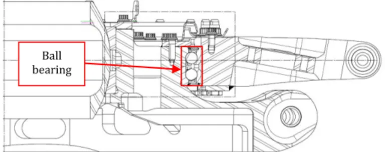
4.2. Advanced multibody simulation of the swashplate assembly
In the context of this work, the nonlinear mechanical solver SAMCEF MECANO has been retained, in association with the pre/post processing software Simcenter 3D. The proposed model takes into account flexibilities of swashplates and the double-row angular-contact ball bearing between these two parts (Figure 5). The deformation of this assembly has an impact on the dynamic load values passing through the main rotor control mechanism. Pitch rod load Rotating scissor load load
Hydraulic actuator load
Fixed scissor
5
Figure 5. Cross-sectional view of the swashplate assembly
The model is based on the centres of the inner and outer rings races. The complete diagram of the swashplate rotor assembly model is shown in Figure 6. In this diagram, the model is presented in a radial plane that cuts two balls each belonging to a row of the bearing. This model is composed of the following elements:
- A super-element of the fixed swashplate (in yellow). This super-element reflects the flexibility of the fixed swashplate arms.
- A super-element of the rotating swashplate (in purple). The bearing outer ring is part of this super-element. - A rigid body called "fixed upper swashplate" (in blue). This body is connected by a hinge joint with the super-element of the fixed swashplate and by a spherical joint with the spherical bearing. This rigid body is an extension of the fixed swashplate and rotates during the simulation at the same speed as the rotating swashplate. This kinematics avoids the use of contact interactions. The hypothesis of rigid body introduced is admissible because of the high stiffness of the fixed swashplate upper part.
- Rigid inner rings (in green) in sliding connection with the fixed upper swashplate. These rigid bodies connect the centre of the fixed upper swashplate to the centres of the inner rings’ races. There are as many inner rings elements as there are balls (2 x 78) in order to ensure correct meshing continuity. The sliding joints allow the application of the bearing preload. A relative displacement imposed on the inner rings models this preload.
- Spring elements (in red). At the right of each ball, a spring connects the centre of the outer ring race to the centre of the inner ring race. 156 spring elements have been created representing the contact stiffness between the balls and the races.
- Rigid elements linked to the outer rings (in orange) which connect the nodes retained of the rotating swashplate super-element to the centres of the outer ring races. 78 rigid bodies attached to the rotating swashplate have thus been created. These rigid bodies are connected to the fixed upper swashplate with a planar joint in order to drive the latter in rotation. Under these conditions, each spring is only loaded in a radial plane and rotates with the rotating swashplate.
Figure 6. Diagram of the swashplate rotor assembly model
Figure 7 presents a global view of the swashplate rotor assembly model. A spring between centres of rings races is enlarged below.
Main rotor axis
Fixed swashplate super-element
Rotating swashplate super-element
Fixed upper swashplate Rigid inner ring
Rigid outer ring
Spring Ball
6
Figure 7. Swashplate rotor assembly model
4.3. Input data of the digital twin
Taking into account the operating principle of the test bench modelled here, the input data of the digital twin are the loads of the axial hydraulic actuators, considered here as constant loads. These loads, measured on the bench test, are applied to the fixed swashplate. Main rotor mast velocity is also an input data of the multibody model.
4.4. Results and model validation
Complementary elements have been connected to the flexible swashplate assembly model to embody the pitch rods, the scissors and the hydraulic actuators. Figure 8 illustrates for these complementary elements, at a given simulation time, the magnitude of the displacement estimated by the digital twin model described above.
Figure 8. Magnitude displacement of the rotor command mechanism
The loads measured during lab test on the rotor control system with the ones obtained by simulation for the digital twin have been sucessfully compared. For example, Figure 9 presents the evolution of the axial pitch rod load. The gap between simulation and test results are low and it validates the approach chosen.
Figure 9. Dimensionless axial load of pitch rod in bench test configuration
7
A similar multibody model of the main rotor control mechanism can be tested in flight configuration. Indeed, a facility which reproduces experimentally the conditions of an helicopter hover flight in ground effect has been used to measure axial loads of pitch rods. Tests results can be compared with simulation as shown on Figure 10.
Figure 10. Dimensionless axial load of pitch rod in flight test configuration
The digital twin gives a correct prediction of these loads. The first order dynamic amplitude is well computed. Nethertheless, dynamic amplitudes of high frequencies are underestimated. This difference is due to the aerodynamic loads applied in the model which are computed by simplified analytical formulas and not by CFD algorithms. The dynamic evolution of aerodynamic loads is not rich enough to get all the excitation applied to the pitch rod.
5. Conclusion
A stepwise approach to build digital twin of helicopter dynamic systems has been presented in this paper. Complexity of helicopter dynamic systems leads to first build and validate digital twins of subsystems, using advanced multibody simulations linked to experimental data. The proposed approach has been illustrated here through the presentation of the developments useful for the creation of a digital twin of the subsystem that constitutes a swashplate rotor assembly. An advanced multibody dynamics model of this assembly has been described. This model takes into account flexibilities of the swashplates and the double-row angular-contact ball bearing. This model has been fed, tested and validated thanks to experimental data provided by bench test and flight test. New flights configurations of this digital twin will be tested to improve the robustness of the approach and new aerodynamic inputs will be used to increase the model representativeness for higher frequencies excitations.
References
[1] Grieves, M., 2014, Digital Twin: Manufacturing Excellence through Virtual Factory Replication, Digital
Twin White Paper.
[2] Tao, F., Zhang, M., Liu, Y., Nee, A.Y.C., 2018, Digital twin driven prognostics and health management for
complex equipment, CIRP Annals - Manufacturing Technology 67 169–172.
[3] Bauchau, O.A., Botasso, C.L., Nikishkov, Y.G., 2001, Modeling Rotorcraft Dynamics with Finite Element
Multibody Procedures, Mathematical and Computer Modelling 33, 1113-1137.
[4] Abhishek, A., Datta, A., Chopra, I., 2009, Prediction of UH-60A Structural Loads Using Multibody Analysis
and Swashplate Dynamics, Journal of Aircraft, Vol. 46, No. 2.
[5] Abhishek, A., 2010, Analysis, validation, prediction and fundamental understanding of rotor blade loads in
an unsteady maneuver, Maryland university.
[6] Grandsen, D., 2011, Aeroservoelasticity of articulated rotor hubs, Carleton university.
[7] Guivarch, D., Mermoz, E., Marino, Y., Sartor, M., 2018, A new modeling framework to predict Helicopter
Dynamic Systems loads, Helicopter Society 74th Annual Forum, Phoenix, Arizona.
[8] Géradin, M., Cardona, A., 2001, Flexible Multibody Dynamics, A Finite Element Approach, John Wiley &
Sons Ltd, England.
[9] Chun, T., Ryu, H., Seong, H.C., Shin, S., Kee, Y., Kim, D., 2013, Structural Analysis of a Bearingless Rotor
Using an Improved Flexible Multibody Model, Journal of Aircraft, Vol. 50, No. 2.
[10] Goulos, I., Pachidis, V., Pilidis, P., 2014, Helicopter Rotor Blade Flexibility Simulation for Aeroelasticity and
8
[11] Benoit, B., Dequin, A.M., Kampa, K., Grünhagen, W.V., Basset, P.M., Gimonet, B., 2000, HOST, a General
Helicopter Simulation Tool for Germany and France, the American Helicopter Society 56th Annual Forum, Virginia Beach, Virginia.
[12] Johnson, W., 2013, A History of Rotorcraft Comprehensive Analyses, American Helicopter Society 69th
Annual Forum, Phoenix, Arizona.
[13] Rodriguez, T., Sharp, R., 2007, Automated Modeling of rotorcraft dynamics with special reference to
AUTOSIM, Automation Science and Engineering.
[14] Ahmad, J. U. and Chaderjian, N. M., High-Order Accurate CFD/CSD Simulation of the UH-60 Rotor in
Forward Flight, NASA Ames Research Center, Moffett Field, CA 94035.
[15] Datta, A., Nixon, M., Chopra, I., 2005, Review of Rotor Loads Prediction With the Emergence of Rotorcraft
CFD, 31st European Rotorcraft Forum, Florence, Italy.
[16] Rajmohan, N., Manivannan, V., Sankar, L., Costello, M., Bauchau, O., 2009, Development of a Methodology
for Coupling Rotorcraft Aeromechanics and Vehicle Dynamics to study Helicopters in Maneuvering Flight, American Helicopter Society 65th Annual Forum, Grapevine, Texas.
[17] Quaranta, G., Bindolino, G., Masarati, P., Mantegazza, P., 2004, Toward a computational framework for
rotorcraft multi-physics analysis: adding computational aerodynamics to multibody rotor models, 30th European Rotorcraft Forum, Marseille, France.
[18] Brentner, K.S, Lopes, L., Chen, H.N, Horn, J.F, 2003, Near Real-Time Simulation of Rotorcraft Acoustics and

![Figure 2. Displacements of blades obtained by multibody simulation [7]](https://thumb-eu.123doks.com/thumbv2/123doknet/12580527.346741/4.892.53.435.83.303/figure-displacements-blades-obtained-multibody-simulation.webp)