HAL Id: hal-03117272
https://hal-mines-albi.archives-ouvertes.fr/hal-03117272
Submitted on 25 Jan 2021
HAL is a multi-disciplinary open access
archive for the deposit and dissemination of
sci-entific research documents, whether they are
pub-lished or not. The documents may come from
teaching and research institutions in France or
abroad, or from public or private research centers.
L’archive ouverte pluridisciplinaire HAL, est
destinée au dépôt et à la diffusion de documents
scientifiques de niveau recherche, publiés ou non,
émanant des établissements d’enseignement et de
recherche français ou étrangers, des laboratoires
publics ou privés.
resulting hooks on the mechanical behaviour of
dissimilar friction stir welded Al2024-T3 to Ti-6Al-4V
overlap joints
Morgane Geyer, Vanessa Vidal, Thomas Pottier, Christine Boher, Farhad
Rezai-Aria
To cite this version:
Morgane Geyer, Vanessa Vidal, Thomas Pottier, Christine Boher, Farhad Rezai-Aria. Investigations
on the material flow and the role of the resulting hooks on the mechanical behaviour of dissimilar
friction stir welded Al2024-T3 to Ti-6Al-4V overlap joints. Journal of Materials Processing Technology,
Elsevier, 2021, 292, pp.1-15/117057. �10.1016/j.jmatprotec.2021.117057�. �hal-03117272�
UNCORRECTED
PROOF
Contents lists available at ScienceDirect
Journal of Materials Processing Tech.
journal homepage: http://ees.elsevier.com
Investigations on the material flow and the role of the resulting hooks on the
mechanical behaviour of dissimilar friction stir welded Al2024-T3 to Ti-6Al-4V overlap
joints
MorganeGeyer
⁎, VanessaVidal, ThomasPottier, ChristineBoher, FarhadRézaï-Aria
Institut Clément Ader (ICA); Université de Toulouse; CNRS, IMT Mines Albi, INSA, ISAE-SUPAERO, UPS; Campus Jarlard, F-81013 Albi, France
A R T I C L E I N F O
Keywords
Friction stir lap welding Material flow Hook
Fracture behaviour X-ray tomography Digital image correlation
A B S T R A C T
During friction stir lap joint welding, hooks are systematically formed at the interface of dissimilar Al2024/ Ti-6Al-4V plates. Various hooks dimensions and shapes are observed according to the welding parameters (weld-ing speed, rotational speed and double-pass). Based on digital image correlation (DIC) dur(weld-ing tensile shear tests, it is found that hooks features govern the fracture behaviours and, hence, the mechanical properties of the over-all welds. In particular, three fracture behaviours are obtained: at the interface, in the Al2024 and across the Ti-6Al-4V plate, which was never reported in dissimilar Al/Ti studies. The aims of this work are (i) to study the influence of FSW parameters on the mechanisms of hooks formation and (ii) to understand the role of both AS and RS hooks on the mechanical behaviour of the welds, by the means of two new approaches. First, hooks are investigated by X-ray tomography which provided some innovative insight into the material flow (3D viewing). Based on these qualitative and quantitative results, hooks are used as tracers and two new scenarios of AS and RS generation are proposed. Then, the contribution of both hooks on the stress distribution is clearly revealed by some calculations of the stresses reached around AS and RS hooks. Contrary to RS hook, AS hook is sharp and, hence, the stress reached at the top of AS hook is characterized by a stress concentration. The results showed that the fracture behaviours are greatly influenced by hooks size and the formation of microstructural defects inside the Ti-6Al-4V, which depend on the welding parameters. In conclusions, this work revealed the relationship be-tween the achievable parameters, the resulting hooks dimensions and the fracture behaviours. In addition, based on the understanding of the material flow, some ways of optimization of the mechanical properties are proposed.
1. Introduction
One of the major challenges of the aeronautical industry is the weight reduction in order to decrease fuel consumption, greenhouse gas emission and increase the flying range. It represents both environ-mental and economical issues. To fulfil these requirements, the aircraft manufacturers tend to replace riveting by advanced joining technolo-gies (Mendez and Eager, 2001). In particular, the demand for a suit-able joining process for dissimilar materials has increased along with newer designs of multi-materials structures (Kulkarni et al., 2015). By placing the right material at the right place, the advantage of each material could be exploited. Welding aluminium alloys to titanium al-loys could be recommended to combine low density and cost with high specific strength and corrosion resistance requirements (Polmear, 1989). Nevertheless, due to their large difference in physical proper-ties, such as melting point, thermal conductivity and thermal expansion
coefficient, the welding of aluminium alloys to titanium alloys consti-tutes a significant challenge, especially through fusion welding processes (Tomashchuk et al., 2015).
Friction stir welding (FSW) is an emerging solid state joining process. Materials are joined through mechanical deformation by the use of a rotating tool which locally heats the assembly by friction. Large plas-tic deformations also contribute to the heating and lead materials to a soft state allowing plastic flow around the tool and then create a metallurgical bond (Mishra and Ma, 2005). FSW was firstly devel-oped to join precipitation hardening aluminium alloys, considered “un-weldable” with conventional fusion welding processes. Currently, FSW tends to be a promising candidate for the production of hybrids struc-tures, as shown by numerous recent studies devoted to the welding of dissimilar alloys (Simar and Avettand-Fenoel, 2017) such as alu-minium to titanium (Kar et al., 2019), alualu-minium to copper (Kush and Vishvesh, 2016), aluminium to magnesium (Shah et al., 2018),
⁎Corresponding author.
E-mail address: morgane.geyer@mines-albi.fr (M. Geyer) https://doi.org/10.1016/j.jmatprotec.2021.117057
UNCORRECTED
PROOF
aluminium to steel (Wan and Huang, 2018) and magnesium to steel (Singh et al., 2019).
FSW of aluminium to titanium is studied in the two main weld-ing configurations: butt and lap joints. In the butt configuration, welds with high joint efficiency can be obtained with a ductile mechanical behaviour. For instance, Dressler et al. (2009) successfully welded Al2024-T3 to Ti-6Al-4V. They obtained a joint with 73% ultimate ten-sile strength of the base Al2024-T3 which failed at the interface. Wu et al. (2015) also achieved an optimized Al6061-T6/Ti-6Al-4V butt weld which reached 68% of Al6061-T6 base metal and failed in the thermo-mechanical affected zone (TMAZ). They found that thermo-mechanical prop-erties and fracture location depend on the characteristics of the inter-metallics compounds (IMC) layer formed at the interface. In the lap con-figuration, mechanical properties of welds are generally lower than butt joints and mechanical behaviour is systematically found to be brittle (Zhou et al., 2019; Picot et al., 2017). The authors also studied the influence of FSW parameters on interfacial microstructure and the me-chanical properties. Yu et al. (2019) showed that two types of Al/Ti interface can be produced: a diffusive or a mixed interface, for low or high heat input respectively. However, regardless of the interfacial crostructure, all welds fail along the interface. Therefore, interfacial mi-crostructure does not seem to correlate with failure and other influen-tial parameter shall be investigated. Contrary to butt joints, lap joints are very sensitive to material flow which leads to the formation of two hooks on both sides of the stir zone. In particular, Yu et al. (2019) observed hooks formation under several welding conditions and do not assess their contribution on the mechanical behaviour of welds despite the fact it is commonly acknowledged that the mechanical strength of FSW lap joints strongly depends on the characteristics of the hooks (Liu et al., 2016). Few studies about Al/Ti friction stir lap welding (FSLW) investigated the impact of hooks on mechanical properties.
Large hooks are generally detrimental to the mechanical properties of lap joints due to the reduction of the effective top plate thickness which induces the decrease of load-carrying capacity of the welds (Yang et al., 2011). In addition, Wang et al. (2019) reported three differ-ent fracture locations in Al6022/mild steel lap joints that were governed by the relative size of hooks on both advancing side (AS) and retreat-ing side (RS). When the height of the RS hook exceeds that of the AS hook, welds failure is observed in the base mild steel and lead to an op-timal joint strength. Hence, optimization of mechanical properties of lap joints requires to control the dimensions of the hooks which are deter-mined by the material flow. Although studies showed that size of hooks increases with the reduction of the welding speed and the increase of the rotational speed (Dubourg et al., 2010), the mechanisms of AS and RS hooks generation need to be further investigated. Besides, most stud-ies characterize hooks from a single cross section. However, FSW is a continuous deformation process and hooks dimensions and shape vary along the weld joint. 3D-techniques would be more relevant since they provide a valuable insight to the material flow. Such 3D representations have not been reported to characterize hooks. Finally, even though it is well known that lap joints are very sensitive to the characteristics of hooks, the contribution of AS and RS hooks on stress distribution re-mains unclear.
The aim of this work is to study the influence of the welding para-meters on the material flow and the role of the resulting hooks on the mechanical behaviour of the welds. Dissimilar FSW lap joints between Al2024-T3 and Ti-6Al-4V alloys are produced at different welding and rotational speeds. In addition, one weld is performed in double-pass. Lap joints are investigated by X-ray computed tomography in order to assess the influence of the process parameters on each hook shape and size. Microstructure is investigated by scanning electron microscopy (SEM). The contribution of hooks and microstructure evolutions is as-sessed through digital image correlation (DIC) during tensile shear
tests. The influence of hooks features and damage mechanisms of Ti-6Al-4V are found critical to determine the mechanical properties.
2. Experimental
2.1. Materials and processings
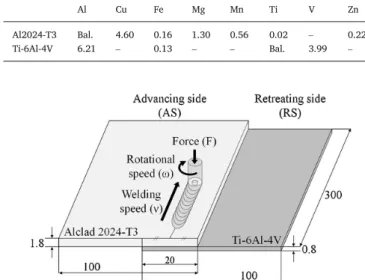
Dissimilar Alclad 2024-T3 aluminium alloy (1.8 mm thickness) and Ti-6Al-4V titanium alloy (0.8 mm thickness) were friction stir welded in a lap configuration. Chemical compositions of these alloys are presented in Table 1.
FSW experiments were conducted using a FANUC M900iB/700 robot at Institut Maupertuis (Bruz, France). This equipment is able to weld up to 10 kN of axial forging force. Each investigated welds were done using force control to ensure a good repeatability of the process (±50 N). To avoid overheating of Al2024 and in order to prevent an excessive wear of the tool, the aluminium alloy plate was placed atop the titanium alloy plate. The advancing side was placed on the side of the aluminium alloy plate free edge of the joint. A schematic illustration of the set up is de-picted in Fig. 1. The welds were performed using a tool with a 2.0 mm height conical pin. The pin entirely penetrates through the Al2024 plate all the way to the upper surface of the Ti-6Al-4V plate. The purpose be-ing to enable the mixture of the two alloys.
In terms of welding parameters, values of rotational speeds ranged from 500 to 1500 rpm, welding speeds ranged from 60 to 240 mm/ min, while the tilt angle was kept constant at 2°. Two series of welds were produced. The first of these was made with a compressive load of 8250 N. Some welds could not be performed due to improper welding conditions leading the tool to plunge through the plates and perforate the Ti-6Al-4V plate. The second serie was made with a lower force of 7000 N in order reduce the heat input and enables the production of the previously unachieved welds. In addition to these two series, one weld was performed in double-pass. Table 2 lists the welding parameters and specifies the welding conditions leading to an excessive heat input.
2.2. Welding characterization 2.2.1. Tomographic analysis
The material flow at the interface between the two alloys is inves-tigated through X-ray computed tomography (CT-scanning). EasyTom 130 tomograph is used for this purpose. The analysed specimen consist
Table 1
Chemical composition of the base materials (weight %).
Al Cu Fe Mg Mn Ti V Zn
Al2024-T3 Bal. 4.60 0.16 1.30 0.56 0.02 – 0.22
Ti-6Al-4V 6.21 – 0.13 – – Bal. 3.99 –
Fig. 1. Schematic illustration of a FSW Al2024-T3/Ti-6Al-4V lap joint (dimensions in mm).
UNCORRECTED
PROOF
Table 2
List of the investigated samples and their respective welding parameters. Welds produced with improper welding conditions are identified by *.
Weld number Force(N) Rotational speed ω(rpm) Welding speed ν (mm/min)
1 8250 500 60 2 8250 500 120 3 8250 500 240 4* 8250 750 60 5 8250 750 120 6* 8250 1000 60 7* 8250 1000 120 8 8250 1000 240 9* 8250 1500 60 10* 8250 1500 120 11* 8250 1500 240 12 – double-pass 8250 500 120 13 7000 750 60 14 7000 1000 120 15 7000 1500 240
in 20 mm wide tensile test coupons cut from the above mentioned sam-ples. The X-ray voltage is set to 113 kV and the power source to 233 μA. Scan resolution, in terms of voxel size, is 20 μm. A serie of 1000 slices in the welding direction is obtained for each sample. Two image pro-cessing programs are developed in order to assess both qualitatively and quantitatively the influence of the welding parameters on the material flow. Thanks to the chemical contrast between aluminium and titanium alloys, their X-ray absorption differ. As a result, greyscale images are ob-tained where aluminium and titanium alloys can be distinguished (Fig. 2a). Segmentation is firstly performed to obtain binary images (Fig. 2b), the titanium alloy can therefore be visualized, alone, from thresholding. Grey threshold values, used for this image processing, were determined for each slice by automatically considering the differences in X-ray ex-posures of successive slices. This is a normal procedure commonly em-ployed in X-ray tomography experiments. This automatic procedure was developed using an in-house Matlab code to obtain 3D reconstruction images. The quantitative analysis was carried out from a second im-age processing program developed on Aphelion software. From the seg-mented images (Fig. 2b), typical parts of the material flow were isolated (Fig. 2d–f) and measured (hooks dimensions and area, and area of the Ti fragments and the cavity). The average values for the whole weld are based on image analysis of 200 slices.
2.2.2. Microstructural characterization
Cross sections of welded joints were prepared for metallographic observations. A standard polishing procedure down to 3 μm diamond paste followed by a finishing with 0.05 μm colloidal silica solution was applied. Macrographs for general observations of hooks were obtained with a tabletop scanning electron microscope (SEM) Hitachi TM3030-Plus. Microstructural observations of the titanium alloy near the inter-face were achieved on samples etched with a weck reagent to reveal the microstructure. Another scanning electron microscope (SEM) No-vaNanoSEM 450 was used to examine the plastic deformation of the Ti-6Al-4V alloy.
2.2.3. Mechanical characterization
The mechanical strength of the welds was measured from tensile shear tests because it is the most widely mechanical test used in the friction stir lap welding (FSLW) literature (Cederqvist and Reynolds, 2011). Since no standard exists for testing FSLW, specimens dimensions and test conditions were chosen according to the most commonly used in the literature (Chen and Nakata, 2008). Rectangular lap shear spec-imens (20 mm width) were water jet cut perpendicular to the welding direction. Spacers were used for weld alignment of specimens in Intron 5800 R tensile machine (Fig. 3). All tests were conducted at room tem-perature with a constant crosshead speed of 1 mm/min. Considering the specific tensile specimen geometry, no extensometer was used and only the force and the crosshead displacement were recorded. Three speci-mens for each welding conditions were tested and failure loads were averaged. During these tensile shear tests, the local displacement fields were determined on the cross section of the specimens, using digital im-age correlations (DIC – VIC-2D). Before testing, the surface of these spec-imens was painted with black and white sprays in order to exhibit a con-trasted random pattern. Strain fields are calculated from spatial deriva-tion of the successive displacement fields measured at a 10Hz frequency.
3. Results
3.1. Weld macrostructure
During friction stir lap welding, the pin (2.0 mm height) penetrates entirely within the Al2024-T3 top plate (1.8 mm thickness) and reaches the upper surface of the Ti-6Al-4V bottom plate. Assuming that plastic strain is volume-conservative, the Ti-6Al-4V is geometrically forced to flow into the aluminium alloy plate on both side of the pin. The com-bination of this penetration and the rotational material flow around the pin leads to the formation of two Ti-6Al-4V hooks which delimit the stir zone on the advancing side (AS) and the retreating side (RS). Their dif-ferent aspects are linked with the asymmetrical material flow on the AS and the RS. On RS, hooks are usually larger and have more complex
Fig. 2. (a) CT-scan images used for post-processing procedures; (b) segmentation for binary images and analyse of (c) the Ti-6Al-4V hooks; (d) the Ti fragments penetrated inside the aluminium alloy plate and (e) the cavity formed by the pin penetration in the titanium alloy plate.
UNCORRECTED
PROOF
Fig. 3. Schematic illustration of lap shear specimen.
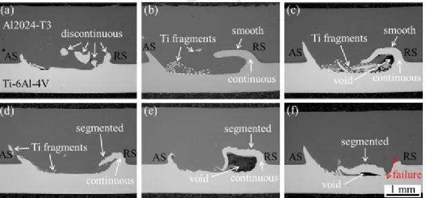
shapes since the material motion and transfer are more significant in RS as demonstrated by Nandan et al. (2007). Six typical interface macro-graphs are presented in Fig. 4. For all welds, AS hooks extend upward and are bent outward the stir zone. These hooks result from the plas-tic shear strain of Ti-6Al-4V along the conical side of the pin. The ac-cumulation of deformation leads to an outgrowth of the titanium alloy which tears complex and coupled modes of ductile rupture within the aluminium alloy plate. RS hooks also extend upward before bending in-ward to penetrate the stir zone. This specific shape could reflect exces-sive plastic deformations. In addition of hooks, Ti-6Al-4V fragments can be observed. They penetrate inside the stir zone near the interface (Fig. 4c) or can even migrate to the middle of the stir zone (Fig. 4b and d). FSW parameters act on hook height and hook shape. In particular, RS hook could be continuous (Fig. 4b–e) or discontinuous (Fig. 4a and f) and present a smooth (Fig. 4a–c) or segmented morphology (Fig. 4d–f). It is visible from Fig. 4, that the process parameters of FSW impact both the AS and the RS hooks height. However, the 2D observations of a single cross section may be insufficient to assess every aspects and
characteristics of the hooks. Hence, successive polishing (Fig. 5) on the same samples may emphasizing the evolution of hooks in terms of height and shape along the joint direction. However, another technique providing 3D visualization, namely X-ray computed tomography, seems more suited to describe the material flow scenario.
3.2. Hooks characterization
Fig. 6 shows the post-weld 3D-reconstructed images according to welding and rotational speeds. Images corresponds to the Ti-6Al-4V dis-tribution inside Al2024 and reveal AS hook, RS hook and Ti-6Al-4V frag-ments. It is worth noticing that because of the scan resolution (voxel size = 20 μm), Ti-6Al-4V fragments with volume lower than 203μm3
cannot be detected. As shown in Fig. 6, the Ti-6Al-4V is not steadily dis-tributed along the joint. Both AS and RS hooks height and aspect vary along welds. The same statement can be reported for Ti-6Al-4V frag-mentation. These observations confirm the interest of using X-ray to-mography to characterize more precisely hooks and Ti-6Al-4V fragments which, then, can be used as tracers to investigate the influence of the welding parameters on the material flow.
In addition to the qualitative results, X-ray computed tomography al-lows a quantitative evaluation of the Ti-6Al-4V distribution. Based on data from the image processing program (refer to Section 2.2.1), several significant relations are noticed between process parameters and char-acteristics of the material flow (Fig. 7). Firstly, it is found that pene-tration depth is proportional to the increase of ω2/ν (Fig. 7a). This
ex-pression corresponds to the definition of the pseudo heat index, widely used in FSW works to describe the heat input provided by the weld-ing parameters (Wang et al., 2014). Arbegast and Hartley (1998) defined this unitized parameter to describe the FSW parameters de-pendence on the heat input. They have shown that for several alu
Fig. 4. Macrographs (SEM-BSE images) showing different hook features for different weld conditions: (a) weld 3; (b) weld 1; (c) weld 14; (d) weld 8, (e) weld 5 and (f) weld 15.
UNCORRECTED
PROOF
Fig. 6. 3D reconstructed images corresponding to the Ti-6Al-4V distribution inside Al2024 according to welding and rotational speeds. Isolines correspond to the values of ω2/ν (given in
rad2mm−1s−1) of the welds.
minium alloys, a general relationship between maximum temperature and FSW parameters can be established:
(1) where Tmis the melting point of the metals, the constant K is ranging
from 0.65 and 0.75, α is between 0.04 and 0.06 and ω and ν are respec-tively the rotational and the welding speeds.
In dissimilar FSLWed Al6061/Ti-6Al-4V, Yu et al. (2019) con-firmed that the variation of peak temperatures, measured by thermo-couples embedded closed to the interface, is also related to ω2/ν. Thus,
the first trend (Fig. 7a) is a consequence of the force control mode which affects the amount of Ti-6Al-4V extruded. It has a direct impact on AS hook height which also increases with ω2/ν, proportionally to
penetration depth of the pin on Ti-6Al-4V (Fig. 7b). On RS, a more complex evolution of RS hook height is noted. It increases first un-til ω2/ν ≃ 5000 rad2mm−1s−1and then declines for higher heat input
(Fig. 7c). On the 3D-reconstructed images it can be observed that this trend is related to an intensification of the bending of RS hook as the heat input increases (Fig. 6). It could be attributed to a severe plastic deformation promoted by the loss of the mechanical properties of the
Ti-6Al-4V with the increase of the heat input. For the welding condition leading to the highest heat input, the severe plastic deformation of the Ti-6Al-4V could explain the failure of the RS hook all along the weld di-rection (Fig. 6a).
The heat input also affects Ti-6Al-4V fragmentation (Fig. 6). For the lowest heat input, no fragments is found due to limited pin penetra-tion depth in Ti-6Al-4V (Fig. 6h). The increase of the heat input pro-motes Ti-6Al-4V displacement inside Al2024. Fragments of Ti-6Al-64V are formed and penetrate inside Al2024 stir zone, preferentially on the AS (Fig. 6e–g). With a further increment of the heat input, and simul-taneously with the bending intensification of the RS hook, it can be ob-served that the fragments remain mainly localized around the interface in between the two hooks (Fig. 6a, b and d).
For the weld performed in double-pass, beam hardening artifacts are obtained and disturb edge detection, making difficult a relevant post-processing (prevent any suitable thresholding between Al2024 and Ti-6Al-4V). However, the partial results from CT-scan suggests that this joint presents larger hooks than the welds produced in single-pass, which was confirmed by the multiple measurements made on cross sec-tions. Hence, the additional deformation provided by the second pass enhances the volume of Ti-6Al-4V being extruded and lead to the largest AS and RS hooks (Fig. 7a and b).
UNCORRECTED
PROOF
Fig. 7. Influence of the process parameters on: (a) the penetration depth, (b) AS hook height and (c) RS hook height. Annotations “6.x” refer to the welding conditions plotted in Fig. 6.
3.3. Ti-6Al-4V deformation
The relative motion of the tool with respect to the metal plates gen-erates complex dynamic solicitations. At the interface of the pin tip and Ti-6Al-4V plate, the sub-surface of Ti-6Al-4V, alike the pin sub-surface, experiences severe shear deformations. Depending on the area in con-tact with the pin, the 3D-stress state changes. A simplified 2D schema is depicted where three regions can be found (Fig. 8). The area under the pin tip experiences a dominant shear compression loading (region I) whereas near the AS and RS hooks dominant shear tensile loadings are prevailing (region II). These regions are separated by pure shear zones (region III).
Fig. 9 exhibits, on the weld which undergoes the most severe defor-mations (weld 15), microstructures from region I (Fig. 9c) and region II (Fig. 9d and e). In both regions, the initial equiaxed microstructure of the base Ti-6Al-4V alloy (Fig. 9b) is strongly modified. For region I (Fig. 9c), two levels of microstructural modifications occur. Firstly, near the interface Al2024/Ti-6Al-4V, where the higher temperatures
Fig. 8. Schematic illustration of the stress state exerted by the pin on the Ti-6Al-4V plate.
are reached, the β phase becomes hardly distinguishable by SEM. This refinement of the microstructure indicates an intensive plastic deforma-tion. Below, in the second level, grains are deformed in the shear direc-tion. In the same direction, some heterogeneities appear in the form of
βgrains elongated in shear bands. Region II extends along the AS hook in a conical shape, alike the geometry of the pin (Fig. 9d). Accumulated segments of Ti-6Al-4V (Fig. 9d) are found at the base of the AS hook. Alike in region I, shear bands (Fig. 9e) are observed. However, unlike the region I, porosities and cracks are formed. These damage mecha-nisms are inherent to the tensile shear stress applied in this region. They take place inside the shear bands in a mechanism of growth of voids which promotes the formation of cracks, as suggested by the zone cir-cled in red in Fig. 9e.
In the zone of shear compression (region I), all the welds present an intensive plastic deformation layer. The thickness of this band depends on the process parameters and more precisely extends with the increase of ω2/ν, which corresponds to the pseudo heat index (Fig. 10). It
indi-cates that pin penetration inside the Ti-6Al-4V plate increases with the increment of the heat input. It can be associated to the decrease of the mechanical resistance of the alloys. AS hook height being also controlled by ω2/ν, it can be assumed that the amount of Ti-6Al-4V displaced
in-side the Al2024 is related to the pin penetration inin-side the lower plate, promoted by the increase of the heat input.
Porosities and cracks are systematically formed in the tensile shear zone (region II). However, depending on the process parameters used, the Ti-6Al-4V distribution is modified. Inspection of the deformation of Ti-6Al-4V was also carry out on weld 13 (Fig. 11a). Instead of Ti-6Al-4V segments formed at the base of the AS hook (Fig. 9d), Ti-6Al-4V frag-ments are produced and locate inside the Al2024 stir zone (Fig. 11b). The microstructure of these fragments, composed of complex shear bands (Fig. 11c), is similar to the Ti-6Al-4V segments depicted in Fig. 9e. Porosities and cracks, emphasized in Fig. 11c, can also be noted. It suggests that these fragments were originally bonded to the titanium alloy plate, as the Ti-6Al-4V segments in Fig. 9d, before being pulled off and penetrate into the stir zone. Therefore, the creation of Ti-6Al-4V fragments seems to result from damage mechanisms which ini
UNCORRECTED
PROOF
Fig. 9. SEM images of weld 15 illustrating the severe plastic deformation of Ti-6Al-4V: (a) SEM-BSE macrograph of shear compression (square no. 1) and shear tensile (square no. 2) regions; (b) SEM-ETD image of the base Ti-6Al-4V alloy (equiaxed microstructure); (c) enlarged SEM-ETD image of the square no. 1; (d) enlarged SEM-ETD image of the square no. 2 and (e) enlarged SEM-ETD image of the square no. 3.
tiate in the tensile shear zone due to its ability to generate voids. Then, Ti-6Al-4V fragments can reach different levels in the thickness of the up-per plate according to the welding parameters, as stated from X-ray to-mography results (Fig. 6).
3.4. Fracture behaviour
From tensile shear tests, three different fracture behaviours (FB) are noticed: (i) fracture across the Al2024-T3 plate above the AS hook (FB I); (ii) fracture along the interface and across both hooks (FB II) and (iii) fracture across the Ti-6Al-4V plate below the AS hook (FB III). Fig. 12 illustrates those three FB. During tensile shear tests the top plate bends above the AS hook regardless the fracture behaviour. It indicates that deformation localizes above the AS hook (plastic hinge). Besides, it sug-gests that AS hook has a significant effect on the mechanical behaviour of the assembly.
The strain field evolution of the three mentioned FB are exhibited in Fig. 13.
For FB I (Fig. 13a), the deformation is first localized at the top of the AS hook while it seems to be of a more diffuse nature on the other side (in and around the large RS hook). Then, the top plate starts to bend while the deformation propagates above AS hook until crack initiation. Finally, fracture occurs across the strained aluminium alloy right above the AS hook.
For FB II (Fig. 13b), the deformation also starts at the top of AS hook within the bending zone of the aluminium alloy plate. Unlike FB I, the deformation localizes across the RS hook section and shear failure of the hook is observed. An interfacial crack then propagates along the weld from the RS hook toward the AS hook. The strain localization on the aluminium alloy plate above the AS hook is visible but do not leads to fracture at this location. Indeed, while the crack reaches to bottom of the AS hook, the change in the interfacial orientation results either in the titanium alloy AS hook to be expelled from the aluminium alloy bulk or a propagation of the crack across the AS hook. Alike in the FB I, the aluminium alloy plate bends above the AS and leads to the align
UNCORRECTED
PROOF
Fig. 10. Influence of the process parameters on the thickness of the intensive plastic de-formation layer produced near the Al2024/Ti-6Al-4V interface.
ment of the two base materials plates. Hence, the loading at failure on the AS hook is close to parallel to its indentation direction which leads to a tensile load on the AS hook which prompts its ejection.
For FB III (Fig. 13c), deformation also reaches both AS and RS hooks leading to the bending of the top plate above AS hook and the alignment of the two edges of the tensile specimen. The major differ-ence concerns the propagation of the deformation between AS and RS hooks. The crack do not propagates all the way towards the AS hook
since the titanium alloy substrate fails before crack completion. It is seen from the DIC measurement that no strain is visible within the titanium alloy prior to failure, hence describing a fracture of brittle nature. Such observation suggests the presence of defects in or around this region. Fi-nally fracture occurs across the titanium alloy below the AS hook.
Regardless the FB involved, it can be noticed that no significant de-formation appears in the rest of the specimen, either the aluminium al-loy or the titanium alal-loy plates. This simple statement confirms the pre-vious observation namely that the mechanical properties of the overall weld joint mainly depends on hooks features.
3.5. Mechanical behaviour
As previously explained, the fracture behaviours of all the welded samples can be classified in three typical behaviour (FB I, FB II and FB III). FBI and FB III comprise only one sample whereas seven samples failed according to FB II. Load–displacement curves obtained for sam-ples belonging to FB I, FB II and FB III and for the weakest base ma-terial Al2024-T3 are presented in Fig. 14. In the case of FB II, only two curves are drawn corresponding to the minimum and maximum failure loads obtained with FB II. Unlike the ductile behaviour of the base aluminium alloy, all welds exhibit a brittle behaviour (Fig. 14a). Both failure loads and displacements at failure are clearly lower for the welded samples, compared to the base material Al2024-T3 (Fig. 14a). This indicates that friction stir welding process generated defects which weakened the joints. The maximum failure load was obtained for the FB II and represents 35% of the ultimate load of the base Al2024-T3 (weld 3). Joints efficiencies (Fig. 14b) were evaluated by the ratio be-tween the failure loads of welds and the ultimate load (UL) of base Al2024-T3. The lowest failure load was obtained for FB III (failure across titanium alloy) and corresponds to the weld 15 which undergoes the most severe plastic deformation (Fig. 9). With an ultimate tensile
Fig. 11. SEM images illustrating the severe plastic deformation of Ti-6Al-4V of the weld 13: (a) SEM-BSE macrograph indicating shear tensile region (square no. 1); (b) enlarged SEM-ETD image of the square no. 1; (c) enlarged SEM-ETD image of the square no. 2.
UNCORRECTED
PROOF
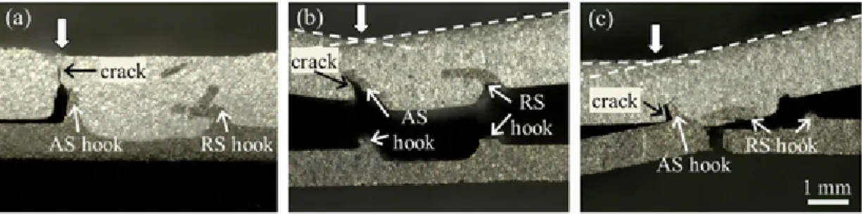
Fig. 12. Photos of the three different fracture behaviours observed: (a) FB I – fracture in the Al2024-T3 plate above the AS hook; (b) FB II – fracture along the interface and across both hooks; (c) FB III – fracture in the Ti-6Al-4V plate below the AS hook. Arrows indicate bending regions of the samples during the tensile shear test.
Fig. 13. Evolution of the strain fields, along cross sections, evaluated by digital image correlation and schematics on the three fracture behaviours: (a) FB I; (b) FB II; (c) FB III. Note that ɛ1 represents the major principle strain.
strength (1100 MPa) more than twice higher than Al2024-T3 (480 MPa), this suggests that under such process parameters, the ti-tanium alloy plate undergoes severe modifications during friction stir welding process leading to the formation of defects. An intermediate
failure load was obtained for FBI, with the weld 12 performed in dou-ble-pass.
It should be mentioned that the stiffness offset (Fig. 14b) between base Al2024-T3 (measured by extensometer) and welded samples (mea
UNCORRECTED
PROOF
Fig. 14. (a) Load–displacement curves of the base Al2024-T3 and the three different fracture behaviours and (b) enlarged picture of dash rectangular region marked in (a) with annotation of the joint efficiency, compared to the ultimate load (UL) of Al2024-T3.
sured by traverse displacement) is related to the difference in displace-ment acquisition.
Typical points of the load–displacement curves for the three FB ob-tained and the strain fields associated are presented in Fig. 15. Each load–displacement curve presents two typical points marked by circles (Fig. 15a–d). The first point corresponds to a change in slope and coin-cides with the crack initiation along the AS hook (Fig. 15a1, b1, c1 and d1). The second point corresponds to the final crack propagation leading to fracture (Fig. 15a2, b2, c2 and d2). For FB I and FB II, a decline in slope (Fig. 15a–c) is observed after crack initiation along AS hook. This could be attributed to the reduction of the load carrying capacity of the joints, related to the decrease of the effective thickness of the aluminium alloy plate. For FB III, two sudden load drops are noticed (Fig. 15d). The first one coincides with the simultaneous crack initiation along the AS hook and along the interface (Fig. 15d1). The second sudden load drop corresponds to the crack initiation across the titanium alloy plate where final fracture occurs (Fig. 15d2).
Relative size of AS and RS hooks influences the mechanical behav-iour (see tables in Fig. 15). AS hook size impacts the first change in slope while RS hook size affects the second typical point of the curves. In particular, a large AS hook causes a change in slope at low displace
ments (Fig. 15a and c). A large RS hook enables a higher displacement between the two typical points (Fig. 15a) whereas a reduced RS hook provokes a sudden load drop (Fig. 15d).
The influence of the process parameters on the failure load and the fracture behaviours is plotted in Fig. 16. A trend can be noted between failure loads of FB II and ω2/ν which indicates that the increase of the
heat input is detrimental to the mechanical properties. With further in-crease of the heat input, the mechanical properties dein-crease significantly and lead to the lowest failure load with FB III, across the titanium alloy plate (weld 15). An intermediate failure load is obtained with FB I. It corresponds to the weld produced in double-pass (weld 12).
The heat input, related to the pseudo heat index ω2/ν (Arbegast and
Hartley, 1998), significantly affects hooks shape (Fig. 6), hooks height (Fig. 7) and the Ti-6Al-4V plastic deformation (Fig. 10). As a conse-quence, the mechanical properties are impacted. In particular, DIC re-sults revealed that AS and RS hooks impact the mechanical behaviour. The influence of the welding parameters on the material flow and the role of the resulting hooks on the stress distribution will be discussed.
Fig. 15. Identification of strain fields associated to two typical points of the load–displacement curves for: (a) FB I (weld 12); (b) FB II – Fmax (weld 3); (c) FB II – Fmin (weld 14) and (d) FB III (weld 15). AS and RS hooks dimensions are exposed. Note that ɛ1 represents the major principle strain.
UNCORRECTED
PROOF
Fig. 16. Influence of the process parameters on the failure loads and the fracture behav-iours.
4. Discussion
4.1. Influence of the welding parameters on the material flow
In the overlap configuration, the generated material flow is complex and leads to the generation of hooks. These features are tightly related to the geometry of the tool and the in-process parameters such as ve-locities and load or depth. Indeed, the input heat (mainly related to the pseudo heat index ω2/ν and F) prompts the loss of the mechanical
resis-tance of the alloys which promotes their deformation and further mate-rial motion. As shown in Fig. 6 (particularly d, f and g), titanium alloy fragments can be transported several millimeters away from their orig-inal location. Accordingly it is reasonable to assume that (i) due to its high thermal conductivity, the aluminium alloy of the top plate is signif-icantly heated at such distance from the tool and (ii) the material em-bedded in the so-called thermo-mechanically affected zone behave like a fluid.
The heat generated by friction (ϕ/m) is classically described by the following relation (Kagnaya et al., 2009):
(2) where τsis the shear stress, Vsis the sliding velocity, α is the heat
par-tition coefficient that represents the portion of heat flux transmitted to the materials and η is the coefficient which specifies fraction of fric-tional power converted into heat. Note that (i) α is defined as the ratio
of the effusivity of both materials (Bonnet et al., 2008) and (ii) it is conventionally consider that 90% of the frictional power is converted into heat and so 10% is devoted to strain hardening and further mi-crostructural evolutions (Bonnet et al., 2008).
Under such formalism, the axial load (here 8250 N) and the rota-tional velocity of the tool ω are responsible for most of the generated heat. More specifically, owing to the surface ratio, the shoulder may be singled out in this matter. Once heated, the material of both alloys can flow around and beneath the tool and then relocate material in order to fill the hole generated behind the tool pathway. The circular flow com-bined with the forward motion of the tool lead to asymmetrical distrib-ution of velocity (Magnus effect) and therefore an asymmetrical distri-bution of the pressure field (Bernoulli's principle) (Lloyd, 1975). The assessment of the location of the stagnation points for every investigated process parameters show that all the incoming material of the AS side is transported to the RS side (Fig. 17). Simultaneously, the axial force and the planar surfaces beneath the shoulder and the pin lead to an upward material extrusion. At the contact Al2024/shoulder, this flow is respon-sible for the flashes virespon-sible on the top free surface, whereas at the con-tact Ti-6Al-4V/pin, this flow results in the formation of hooks. In par-ticular, due to the force control of the process the amount of Ti-6Al-4V displaced into Al2024 is controlled by the penetration depth of the pin, which is enhanced with the increase of the heat generated (related to the pseudo heat index ω2/ν).
Thus, the formation of both hooks results from a combined contribu-tion of the circular and upward flows. Assuming that the velocity com-position is different on both side, two scenarios emerge:
• AS hook generation: the material is lifted and deposited as such. The extrusion results mostly from the centrifugal force and is very com-parable to the flashes observed at the top of the aluminium alloy plate. However owing to the feed motion of the tool only the sec-tion away from the tool pathway remains post-process: namely the AS hook (Fig. 17).
• RS hook generation: the stirred material is first lifted upward by the pin penetration, then transported around the tool and finally de-posited behind it when its velocity decreases (Fig. 17). For this rea-son the Ti-6Al-4V fragments, which penetrated inside the stir zone, preferentially located on this side (refer to Section 3.2 and Fig. 6). In addition, the higher circumferential velocity on this side prevents from any outward extrusion. On the contrary the shape of the veloc-ity field behind the tool leads to locate the generation zone around the central axis of the tool pathway (Hamilton et al., 2013). The
UNCORRECTED
PROOF
schematic of Fig. 17 also point out the fact that the velocity compo-sition of ω and ν controls the angle at which the material is ejected behind the tool and thus the length of the penetrating titanium extru-sion.
Beyond these rough considerations, the wide variety of shapes and size of the generated hooks of the present study leads to consider that the process parameter play a major role in the material extrusion and deposition. It is therefore relevant to use hooks as marker of the material flow even though post-mortem observations lead to a drastic simplifica-tion of a way more complex phenomenon.
Fig. 18 presents optical microscope images of the welds cross sec-tions produced with increasing heat input. It is first seen that the force control of the process imposes that when the heat input increases, the penetration depth of the tool increases as well. Consequently, it is seen from Fig. 18 that the amount of extruded material being lifted up also increases. On the AS side, the hooks exhibit a flash like shaped regard-less of the heat input. On this side height of the hook profile increases with the heat input (Figs. 18 and 7a) which is consistent with larger amount material being extruded. On the RS side the thickness and the length of the hooks increases with the heat input, here again owing to the amount of material being transported. However, on this side, the shape of the hooks and its continuous nature seem significantly affected by the plastic deformation capacity of the Ti-6Al-4V.
At low heat input, the material behaves with a high viscosity. Its plastic flow capacity around the tool is affected by the lower tempera-ture. On the RS side, the relative pressure is lower and prompts a ten-sile-like loading responsible for local micro-tearing, crack initiation and material failure.
At intermediate heat input, clear hooks are formed on RS, the heat is sufficient to allow material extrusion and subsequent motion. At such temperature, the strain at failure is increased and allows large strain within the titanium alloy (Lee and Lin, 1998). This is why RS bending intensifies.
At high heat input, the stirred titanium alloy is less viscous and is extruded in large quantities owing to the force control of the process which leads to deeper penetrations of the pin. In addition, the alu-minium alloy being also over heated offers no resistance to titanium al-loy particle motion. Hence, the extruded material is easily transported
around the tool and ejected behind it. Even though the rise of temper-ature tends to increase the strain at failure, the circumferential velocity leads to particle projection responsible for the generation of a discontin-uous hook (Fig. 18c and a).
Post-mortem analysis from CT-scan reconstruction of the post-process titanium alloy plate (Fig. 6) offers a valuable insight at the material flows involve in friction stir welding. A clear dependency of the hooks shape and size to the process parameters is observed. More specif-ically, the pseudo heat index (Arbegast and Hartley, 1998) seems to act as a key factor in this matter.
4.2. Influence of hooks on stress distribution
The most obvious weld characteristic observed having an influence on the mechanical behaviour is the formation of hooks. As pointed out by DIC results, hooks disturb stress distribution during tensile shear tests and generate two strain localization areas (Fig. 13). The first one is cated on the Al2024 above the AS hook, whereas the second one is lo-cated on the Ti-6Al-4V at the base of the RS hook. Fig. 19 defines these two areas as respectively “critical zone A” and “critical zone B”. During tensile shear tests, the critical zone A mainly undergoes tension whereas critical zone B undergoes shearing.
The mechanical properties of the overall welds are govern by the peak stresses reached in critical zones A and B, which are influenced by hooks features. The joint efficiency previously defined (part 3.5) ex-presses the global load bearing capacity of the joint with respect to the weakest material, i.e. the aluminium alloy. Thus, this “macro” joint ef-ficiency does not reflect the stresses locally reached in critical zones A and B. To better understand the role of hooks on the stress distribution during tensile shear tests, the stress reached in critical zones A and B are estimated and two new “local joint efficiencies A and B” will be defined. In critical zone A, a strain field with a butterfly shape, typically encountered at the notch tip (Pilkey and Pilkey, 2008), is formed at the top of AS hook due to its higher sharpness compared to RS hook. Therefore, AS hook can be considered as a notch which induces a stress concentration, characterized by a stress concentration factor (Pilkey and Pilkey, 2008). The stress concentration factor (Kt) relates
the peak stress (stress in the perturbed region) and the nominal stress
Fig. 18. Optical microscope images of the welds cross sections: (a) weld 3; (b) weld 1 and (c) weld 11 sorted in ascending order of ω2/ν increasing. Note that weld 11 was produced with
UNCORRECTED
PROOF
Fig. 19. Definition of critical zones A and B during tensile shear test.
(stress without notch) as follow:
(3) Considering the welds aspect, Ktis estimated on the assumption that
a rectangular plate in tension with fillet is the closer geometry of welds (Fig. 20). Geometrical characteristics of the welds are used: the thick-ness of the base material Al2024 plate D, by taking into account its thin-ning, the effective thickness above AS hook d, the AS hook height t and the notch tip radius r. The ratio r/t is kept constant at 0.5 for all welds and data from the image processing program (refer to Section 2.2.1) are used for d and t variables. Values ranging between 1.8 and 2.15 are ob-tained.
A local joint efficiency A is defined as the ratio between the tensile peak stress reached in critical zone A and the ultimate tensile strength of the base Al2024-T3. The results are plotted in Fig. 21 and point out that FBI results from a severe stress concentration in critical zone A. Lo-cally, the peak stress at the top of AS hook reaches the ultimate ten-sile strength of Al2024 (local joint efficiency A superior to 100%) and leads to crack initiation and fracture across the aluminium alloy. For FBII and FBIII, the peak stresses reached in critical zone A are insuffi-cient (local joint efficiency A lower than 100%) and fracture across the aluminium alloy plate (critical zone A) is not achieved. Size of AS hook mainly govern the stress concentration factor in critical zone A. High AS hook height accentuates the stress concentration resulting in the change in slope observed for low displacement through the plastic hinge phe-nomenon (Fig. 15). Insufficient AS hook heights do not induce failure across Al2024 and lead to a further increase of the load, which will im-pact the stress reached in critical zone B.
In critical zone B, the shear stress (τ) reached across the RS hook can be estimated from:
(4) where F is the failure load and SRSthe RS hook shear cross section,
de-termined from data from the image processing program.
A local joint efficiency B is defined as the ratio between the shear stress reached in critical zone B and the ultimate shear stress of the base Ti-6Al-4V. The results are plotted in Fig. 22 and show that the stress reached in critical zone B exceeds the ultimate shear stress of Ti-6Al-4V (local joint efficiency B superior to 100%) for FBII. Failure of RS hook leads to crack propagation and fracture across the interface (FBII). The peak stress was not calculated for FB III due to the limited size of RS hook, which results from its failure (Fig. 15d). Crack can easily propagates along the interface due to the lack of any obstacle.
This is why a sudden load drop was observed in load–displacement curve (Fig. 15d). It emphasizes the mechanical anchorage action of RS hook. For FB I, the high RS hook size (Fig. 15a) inhibits crack propaga-tion in critical zone B. By its acpropaga-tion of mechanical anchoring, RS hook postpones crack initiation and increases the displacement at failure, as presented in Fig. 15a.
Finally, the fracture behaviours mainly result from the influence of both AS and RS hooks on the stress distribution during tensile shear test. It is found that the RS hook plays the role of mechanical anchoring while AS hook acts as a notch due to its high sharpness. Subsequently, the stress concentration at critical zone A, along with the decrease of the ef-fective thickness of the upper plate, lead to impair the load carrying ca-pacity of the weld and thus explains the slope drop observed after crack initiation along AS hook (Fig. 15).
FBI occurs for large AS hook, prompted by the second pass. The peak stress reached in critical zone A is equivalent to the ultimate strength of Al2024. FBII and FBIII occur for lower hooks dimensions. The peak stress reached in critical zone B is equivalent to the ultimate shear strength of Ti-6Al-4V. FB II occurs for complete crack propagation along the interface. FB III results from the presence of defects in Ti-6Al-4V. Microstructural modifications, prompted by the high heat input, impel the crack to deviate though the damaged titanium alloy (weld 15) and ultimately leads to a tensile fracture of the thinned titanium plate.
4.3. Relationship between the welding parameters, hooks dimensions and mechanical behaviours
Influence of hooks dimensions on the mechanical behaviour is sum-marized in Fig. 23. The relationship with the FSW parameters is also highlighted. FB II is the most represented fracture behaviour. Welds per-formed in single-pass mainly lead to hooks with similar dimensions. The resulting AS hook height is insufficient to initiate crack propagation in critical zone A. Therefore, crack initiates in critical zone B. Larger AS hook, and hence FB I, could not be performed in single-pass. A higher heat input leads to improper welding conditions (tool plunge through the Al2024 top plate and the perforation of the Ti-6Al-4V bottom plate) as obtained with welds 4, 6, 7, 9, 10 and 11 (Table 2). The higher ap-propriate heat input in single-pass is performed with weld 15. However, a fractured RS hook and a pre-cracked region in the titanium alloy plate (Fig. 9) are observed. These specific modifications, characterized by a high AS hook and a low RS hook, lead to fracture across titanium alloy (FB III) (Fig. 23).
Large AS and RS hooks, promoted by the additional heat input pro-vided by the second pass, lead to crack initiation in critical zone A and, therefore, FB I. Higher hooks dimensions could be obtained by varying the welding parameters in double-pass. However according to the previ-ously exposed considerations, such feature is certainly not desirable in terms of mechanical properties of the joint.
To sum up: a low AS hook and a high RS hook would increase the mechanical properties, which is in good accordance with the results of (Wang et al., 2019). The suppression of the AS hook could avoid a stress concentration in critical zone A whereas a higher RS hook could promote a mechanical anchoring action. Nevertheless, these optimized hooks dimensions coincide with the non-achievable region (Fig. 23).
UNCORRECTED
PROOF
Fig. 21. Local joint efficiency estimated in critical zone A for each FB (7 tests failed ac-cording to FBII against 1 test acac-cording to FBI (weld 12) and 1 test acac-cording to FBIII (weld 15)).
Fig. 22. Local joint efficiency estimated in critical zone B for each FB (7 tests failed ac-cording to FBII against 1 test acac-cording to FBI (weld 12) and 1 test acac-cording to FBIII (weld 15)).
Fig. 23. Relationship between the achievable FSW parameters, the resulting AS and RS hooks dimensions and fracture behaviours for a given tool and loading configuration.
According to the understanding of the material flow, the feasibility of a reduced AS hook combined with a large RS hook is not expected. In-deed, AS hook height being controlled by the pin penetration depth, the lowest AS hook size achievable would be equivalent to the min-imal penetration depth of the pin, i.e. 200 μm (2.0 mm pin height against 1.8 mm top plate thickness). For these conditions, the amount of Ti-6Al-4V extruded is low and would generate a limited RS hook height. It should be mentioned that these conclusions are drawn for a given tool and could drastically differ with another tool geometry and dimensions. In particular, the decrease of the pin length could reduce the amount of extruded Ti-6Al-4V penetrated inside the aluminium al-loy plate. Such conditions, would lead to lower hooks size. Therefore the mechanical resistance of the weld is expected to increase. Besides, AS and RS hooks being asymmetrical (different size, shape and sharpness), different results could be obtained in the other loading configuration
(modification of the relative position of AS and RS hook), as reported by Yang et al. (2011). In conclusion, this study pointed out that dissim-ilar friction stir lap welds are very sensitive to FSW parameters such as the welding speed, the rotational speed, the number of pass and to the force control mode. Modification of the tool and the loading configura-tion could constitutes some ways to optimize the mechanical resistance of welds.
5. Conclusion
In this present work, Al2024-T3 to Ti-6Al-4V overlap joints were produced with various welding speeds and rotational speeds. The forge force was modified in order to achieve welds with appropriate heat in-put. In addition, one weld was performed with double-pass. Three dif-ferent fracture behaviours were observed: (i) FB I, across the Al2024-T3 plate above the AS hook; (ii) FB II, along the interface and (iii) FB III, across the Ti-6Al-4V plate below the AS hook. The formation of hooks, as well as their contributions on the mechanical behaviour of welds were investigated. Based on these observations and analysis, the following conclusions could be drawn:
1. The formation of hooks results from the contribution of the upward and circular flows. First, due to the force control of the process, the amount of Ti-6Al-4V extruded increases with the heat input, related to the pseudo heat index ω2/ν. However, the volume of Ti-6Al-4V
transported to form AS and RS hooks is not distributed in the same way due to the asymmetrical distribution of velocity fields. AS hook is formed due to the extrusion action of the tool, alike flashes. RS hook results from material extrusion and deposition behind the tool. 2. FSW parameters impact the material extrusion and deposition, and
therefore hooks shape and size. AS hook keeps a flash like shaped and its height increases with the heat input (ω2/ν), owing to the force
control of the process. Evolution of RS hook height and shape is more complex. The volume of RS hook is also proportional to the heat in-put (ω2/ν). However, the deposition of Ti-6Al-4V is also impacted by
its plastic deformation capacity. RS hook height firstly increases with the heat input, which allows a large strain within the Ti-6Al-4V. Sub-sequent increase leads to an intensification of RS hook bending and, hence, RS hook height decreases. For high heat input, the high cir-cumferential velocity leads to material projection and failure of the RS hook.
3. AS and RS hooks disturb the stress distribution at their vicinity. They form two critical zones namely critical zone A (shear tensile in Al2024 above AS hook) and critical zone B (shear compression in Ti-6Al-4V at the base of RS hook). Crack initiation in one of these regions directly leads to further crack propagation and structural fail-ure. Hooks dimensions control the stresses reached in critical zones A and B.
4. FB I is obtained for large AS and RS hooks which lead to a peak stress equivalent to the UTS of Al2024-T3 in critical zone A. Crack initi-ated along AS hook can propagate across the aluminium alloy plate. The additional heat input provided by the second pass results in high hooks sizes and amplifies this very phenomenon.
5. FB II is obtained for limited sizes of AS and RS hooks. The peak stress reached in critical zone A is not sufficient to prompt failure within the upper plate. A further increase of the load applied in critical zone B is observed. Crack initiates in critical zone B due to a peak stress equivalent to the shear stress of Ti-6Al-4V. Then, the crack propa-gates along the interface due to the lack of any defects.
6. FB III is also obtained for limited sizes of AS and RS hooks. Frac-ture across Ti-6Al-4V occurs due to the formation of a pre-cracked zone in the Ti-6Al-4V, related to the severe plastic deformation of the Ti-6Al-4V and thinning of the bottom plate.
UNCORRECTED
PROOF
Authors’ contributionMorgane Geyer: conceptualization, formal analysis, investigation, writing – original draft, visualization. Vanessa Vidal: conceptualization, writing – review & editing, supervision. Thomas Pottier: conceptual-ization, writing – review & editing. Christine Boher: conceptualconceptual-ization, writing – review & editing, supervision, funding acquisition, project ad-ministration. Farhad Rézaï-Aria: conceptualization, writing – review & editing, supervision.
Declaration of Competing Interest
The authors report no declarations of interest.
Acknowledgements
This work is part of a National project IMPAACT (Intelligent and Multi-material Process of Assembly: Aluminum alloys Coupled with Ti-tanium) in collaboration with AVANTIS Group and MAUPERTUIS Insti-tute and funded by DGA. The authors thank the different partner as well as the technician team of the ICA institute.
References
Arbegast, W.J., Hartley, P.J., 1998. Characteristics of friction stir welded aluminum alloys. In: Proceedings of the Fifth International Conference on Trends in Welding Research. Pine Mountain, USA.
Bonnet, C., Valiorgue, F., Rech, J., Hamdi, H., 2008. Improvement of the numerical modeling in orthogonal dry cutting of an aisi 316l stainless steel by the introduction of a new friction model. CIRP J. Manuf. Sci. Technol. 1, 114–118 High Performance Cutting doi:10.1016/j.cirpj.2008.09.006.
Cederqvist, L., Reynolds, A.P., 2011. Factors affecting the properties of friction stir welded aluminum lap joints. Weld. J. 80, 281S–287S.
Chen, Y., Nakata, K., 2008. Friction stir lap joining aluminum and magnesium alloys. Scr. Mater. 58, 433–436. doi:10.1016/j.scriptamat.2007.10.033.
Dressler, U., Biallas, G., Mercado, U., 2009. Friction stir welding of titanium alloy tial6v4 to aluminium alloy aa2024-t3. Mater. Sci. Eng. A 526, 113–117.
Dubourg, L., Merati, A., Jahazi, M., 2010. Process optimisation and mechanical properties of friction stir lap welds of 7075-t6 stringers on 2024-t3 skin. Mater. Des. 31, 3324–3330. doi:10.1016/j.matdes.2010.02.002.
Hamilton, C., Kopyciaski, M., Senkov, O., Dymek, S., 2013. A coupled thermal/material flow model of friction stir welding applied to Sc-modified aluminum alloys. Metall. Mater. Trans. A 44, 1730–1740. doi:10.1007/s11661-012-1512-y.
Kagnaya, T., Boher, C., Lambert, L., Lazard, M., Cutard, T., 2009. Wear mechanisms of wc-co cutting tools from high-speed tribological tests. Wear 267, 890–897. Kar, A., Suwas, S., Kailas, S., 2019. Multi-length scale characterization of microstructure
evolution and its consequence on mechanical properties in dissimilar friction stir welding of titanium to aluminum. Metall. Mater. Trans. A 50, 5153–5173. Kulkarni, N., Mishra, R., Yuan, W., 2015. Friction Stir Welding of Dissimilar Alloys
and Materials. Friction Stir Welding and Processing. Elsevier Science.https://books. google.fr/books?id=v9-oBAAAQBAJ.
Kush, P.M., Vishvesh, J.B., 2016. A review on dissimilar friction stir welding of copper to aluminum: process, properties, and variants. Mater. Manuf. Process. 31, 233–254. doi:10.1080/10426914.2015.1025971.
Lee, W.S., Lin, C.F., 1998. Plastic deformation and fracture behaviour of Ti6AJ4V alloy loaded with high strain rate under various temperatures. Mater. Sci. Eng. A 241, 48–59. doi:10.1016/S0921-5093(97)00471-1.
Liu, H., Hu, Y., Peng, Y., dou, C., Wang, Z., 2016. The effect of interface defect on mechanical properties and its formation mechanism in friction stir lap welded joints of aluminum alloys. J. Mater. Process. Technol. 238, 244–254. doi:10.1016/ j.jmatprotec.2016.06.029.
Lloyd, D., 1975. An introduction to fluid mechanics and heat transfer. JM Kay and RM Nedderman. Cambridge University Press. 1974, 320 pp. illustrated.£ 6.30 (paperback). The Aeronautical Journal 79, 183.
Mendez, P.F., Eager, T.W., 2001. Welding processes for aeronautics. Adv. Mater. Process. 159, 39–43.
Mishra, R., Ma, Z., 2005. Friction stir welding and processing. Mater. Sci. Eng. R: Rep. 50, 1–78. doi:10.1016/j.mser.2005.07.001.
Nandan, R., Roy, G., Lienert, T., Debroy, T., 2007. Three-dimensional heat and material flow during friction stir welding of mild steel. Acta Mater. 55, 883–895. doi:10.1016/ j.actamat.2006.09.009.
Picot, F., Gueydan, A., Hug, E., 2017. Influence of friction stir welding parameters on titanium-aluminum heterogeneous lap joining configuration. In: AIP Conference Proceedings 1896. American Institute of Physics. doi:10.1063/1.5008053. Pilkey, W., Pilkey, D., 2008. Peterson’s Stress Concentration Factors. Wiley.https://books.
google.fr/books?id=JUAdYkKh0V8C.
Polmear, I.J., 1989. Light Alloys: Metallurgy of the Light Metals.
Shah, L.H., Othman, N.H., Gerlich, A., 2018. Review of research progress on aluminium to magnesium dissimilar friction stir welding. Sci. Technol. Weld. Joining 23, 256–270. doi:10.1080/13621718.2017.1370193.
Simar, A., Avettand-Fenoel, M.N., 2017. State of the art about dissimilar metal friction stir welding. Sci. Technol. Weld. Joining 22, 389–403. doi:10.1080/ 13621718.2016.1251712.
Singh, V.P., Patel, S.K., Kumar, N.B.K., 2019. Parametric effect on dissimilar friction stir welded steel-magnesium alloys joints: a review. Sci. Technol. Weld. Joining 24, 653–684. doi:10.1080/13621718.2019.1567031.
Tomashchuk, I., Sallamand, P., Cicala, E., Peyre, P., Grevey, D., 2015. Direct keyhole laser welding of aluminum alloy aa5754 to titanium alloy ti6al4v. J. Mater. Process. Technol. 217, 96–104. doi:10.1016/j.jmatprotec.2014.10.025.
Wan, L., Huang, Y., 2018. Friction stir welding of dissimilar aluminum alloys and steels: a review. Int. J. Adv. Manuf. Technol. 99, 1781–1811. doi:10.1007/s00170-018-2601-x. Wang, M., Zhang, H., Zhang, J., Zhang, X., Yang, L., 2014. Effect of pin length on hook size and joint properties in friction stir lap welding of 7b04 aluminum alloy. J. Mater. Eng. Perform. 23, 1881–1886. doi:10.1007/s11665-014-0936-5.
Wang, T., Sidhar, H., Mishra, R.S., Hovanski, Y., Upadhyay, P., Carlson, B., 2019. Effect of hook characteristics on the fracture behaviour of dissimilar friction stir welded aluminium alloy and mild steel sheets. Sci. Technol. Weld. Joining 24, 178–184. doi:10.1080/13621718.2018.1503801.
Wu, A., Song, Z., Nakata, K., Liao, J., Zhou, L., 2015. Interface and properties of the friction stir welded joints of titanium alloy ti6al4v with aluminum alloy 6061. Mater. Des. 71, 85–92.
Yang, Q., Li, X., Chen, K., Shi, Y., 2011. Effect of tool geometry and process condition on static strength of a magnesium friction stir lap linear weld. Mater. Sci. Eng. A 528, 2463–2478. doi:10.1016/j.msea.2010.12.030.
Yu, M., Zhao, H., Jiang, Z., Zhang, Z., Xu, F., Zhou, L., Song, X., 2019. Influence of welding parameters on interface evolution and mechanical properties of FSW Al/Ti lap joints. J. Mater. Sci. Technol. 35, 1543–1554.
Zhou, L., Yu, M., Zhao, H., Jiang, Z., Guo, F., Song, X., 2019. Dissimilar friction stir welding of aa6061 and ti6al4v alloys: a study on microstructure and mechanical properties. J. Manuf. Process. 48, 119–126.