CLOUD BASED IP MULTIMEDIA SUBSYSTEM (IMS) ARCHITECTURE TO INTEGRATE VEHICULAR AD HOC NETWORK (VANET) AND IMS
MAHSIMA RAHIMI
DÉPARTEMENT DE GÉNIE INFORMATIQUE ET GÉNIE LOGICIEL ÉCOLE POLYTECHNIQUE DE MONTRÉAL
MÉMOIRE PRÉSENTÉ EN VUE DE L’OBTENTION DU DIPLÔME DE MAÎTRISE ÈS SCIENCES APPLIQUÉES
(GÉNIE INFORMATIQUE) AOÛT 2014
Ce mémoire intitulé:
CLOUD BASED IP MULTIMEDIA SUBSYSTEM (IMS) ARCHITECTURE TO INTEGRATE VEHICULAR AD HOC NETWORK (VANET) AND IMS
présenté par: RAHIMI Mahsima
en vue de l’obtention du diplôme de: Maîtrise ès Sciences Appliquées a été dûment accepté par le jury d’examen constitué de :
M. PIERRE Samuel, Ph.D., président
M. QUINTERO Alejandro, Doct, membre et directeur de recherche Mme BELLAÏCHE Martine, Ph.D., membre
DEDICATION
I dedicate this thesis to my husband, Mehran, who has provided support and confidence during the challenges of graduate school and life. This work is also dedicated to my family for all their love and support.
I would like to thank Professor Alejandro Quintero, my master’s thesis advisor for his feedback in the area of my thesis and for his support, guidance and advice that helped me complete my thesis. I would like also to thank Nasrin Taherkhani, Éric Mayeul Fafolahan, Mohab Ali, Ryan Shaygan, Richard and all my past and present colleagues at LARIM for the enriching discussions we had. Finally, I would like to thank my dear husband Mehran. He has stood by me in all my projects and providing support and confidence.
RÉSUMÉ
Les réseaux Ad Hoc véhiculaires (VANET) représentent une technologie spéciale, dans la catégorie des réseaux ad hoc sans fils. Ils visent la sécurité routière, une plus grande efficacité et une meilleure organisation au sein des systèmes de transport. Ils favorisent l’avènement de nouvelles applications relatives à l’ingénierie, la gestion de trafic, la dissémination d’informations d’urgence pour éviter les situations critiques, le confort et le divertissement, ainsi que plusieurs autres «applications utilisateur».
Le sous-système multimédia IP (IP Multimedia Subsystem, IMS), a été standardisé par le projet «Third Generation Partnership Project» (3GPP) pour les réseaux hétérogènes avec un support de la qualité de service. Cette plateforme a été proposée dans le but d’offrir aux utilisateurs finaux des services multimédia tels que la voix, les données et la vidéo, la facturation ainsi que l’intégration des services tout-IP. Avec l’avènement de IMS, il est désirable d’offrir aux utilisateurs des réseaux véhiculaires (VANET), un accès aux services de ce sous-système. Cependant, les caractéristiques de ces réseaux posent des difficultés majeures pour le contrôle des performances des services IMS. Par ailleurs, le «réseau cœur » de IMS présente aussi des limitations telles que le contrôle centralisé, la faible efficacité et une faible évolutivité au niveau des équipements du réseau cœur en comparaison aux infrastructures de réseau utilisant le Cloud Computing. Le Cloud Computing est un nouveau paradigme des technologies de l’information, offrant des ressources extensibles dynamiquement, souvent au moyen de machines virtuelles et accessibles en tant que services sur Internet. La migration de l’IMS au sein du Cloud peut permettre d’améliorer les performances de l’infrastructure IMS. Ce projet propose une architecture novatrice d’intégration des réseaux VANET, IMS et le Cloud Computing.
Vehicular Ad Hoc network (VANET) is a special technology in wireless ad hoc networks. It can be used to provide road safety, efficiency and traffic organization in transportation system. Thus, new applications arise in several fields such as traffic engineering, traffic management, dissemination of emergency information in order to avoid critical situations, comfort, entertainment and other user applications.
IP multimedia Subsystem (IMS) is a subsystem, standardized with Third Generation Partnership Project (3GPP). The IMS supports heterogeneous networking with Quality-of-Service (QoS) policy. The goal of this platform is to integrate All-IP services and to provide final user with multimedia services such as voice, data and video with appropriate billing mechanisms. With the advent of the IP Multimedia Subsystem, it is desirable to provide VANET end-users with IMS services. However, characteristics of VANET cause major challenges to control the performance of IMS services. On the other hand, the traditional IMS core network faces a set of problems such as centralized control, low efficiency and poor scalability of core equipment, compared with the IT environment using Cloud Computing. Cloud Computing is an emerging paradigm in the field of information technology. In this new paradigm, dynamically scalable and often virtualized resources are provided as services over the Internet. The migration of IMS to cloud can improve its performance. This project proposes an innovative architecture in order to integrate VANET, IMS and Cloud Computing.
TABLE OF THE CONTENTS
DEDICATION ... iii
ACKNOWLEDGEMENTS ... iv
RÉSUMÉ ... v
ABSTRACT ... vi
TABLE OF CONTENTS ... vii
LIST OF THE TABLES ... ix
LIST OF THE FIGURES ... x
TABLE OF ACRONYMS AND ABBREVIATIONS ... xi
CHAPTER 1 INTRODUCTION ... 1
1.1 Definition and basic concept ... 3
1.1.1 Vehicular Ad Hoc Networks (VANETs) ... 3
1.1.2 IP Multimedia subsystem (IMS) ... 5
1.1.3 Cloud Computing ... 7
1.2 Aspects of the problem ... 8
1.3 Research Objectives ... 9
1.4 Outline ... 9
CHAPTER 2 STATE OF THE ART ... 10
2.1. Vehicular Ad-hoc Network (VANET) ... 10
2.1.1 Characteristics of VANET ... 10
2.1.2 Applications of VANETs ... 11
2.1.3 Architecture of VANET ... 12
2.2 IP Multimedia Subsystem (IMS) ... 13
2.2.1 IMS and Protocols ... 16
2.2.2 Presence Framework of IMS ... 17
2.3.2 MIH elements ... 22
2.4 Cloud Computing ... 23
2.4.1 Cloud Computing Models ... 24
2.5 IMS and Cloud Computing ... 25
CHAPTER 3 PROPOSED ARCHITECTURE ... 27
3.1 Proposed Architecture ... 27
3.2 Assumption ... 29
3.3 Architecture Principals ... 29
3.4 Architecture topology and interactions ... 30
3.4.1 Roles of defined Units in Gateway Architecture ... 33
3.4.2 Roles of defined servers in Cloud ... 35
3.4.3 Interactions ... 35
3.5 Global Architecture ... 37
3.6 Protocols ... 38
3.7 Message follow ... 39
CHAPTER 4 Implementation and validation ... 45
4.1 Mathematical Model ... 45
4.1.2 Latency Analysis via Wi-Fi ... 48
4.1.3 Latency Analysis via LTE ... 51
4.1.4 Total Communication delay ... 55
4.2 Validation ... 59
4.2.1 Architecture comparison ... 59
4.2.2 Simulation and results ... 61
CONCLUSION ... 65
5.1 Summary of the work ... 65
5.2 Limitation of this work ... 68
5.3 Future work ... 68
LIST OF THE TABLES
Table 4.1 : Formula Parameters ... 50
Table 4.2 : Calculated Parameters in Wi-Fi Delay Formula ... 51
Table 4.3 : IMT-A Latency Requirements ... 51
Table 4.4 : Comparison among proposed architecture for Integration VANET and IMs ... 59
Table 4.5 : Simulation parameters In Freeway Scenario ... 62
LIST OF THE FIGURES
Figure 1.1 : VANETS Structure [2] ... 4
Figure 1.2 : VANET system Architecture [11] ... 6
Figure 1.3 : Multimedia Subsystem (IMS) CORE[3] ... 7
Figure 2.1 : The relation among SIP servers and HSS ... 12
Figure 2.2 : Registration at IMS level[12] ... 14
Figure 2.3 : 3GPP IMS architecture overview ... 15
Figure 2.4 : 4G architecture and IMS ... 17
Figure 2.5 : Communication between local and remote MIH entities[23] ... 19
Figure 2.6 : Deployment Model[24] ... 19
Figure 2.7 : Cloud Computing Reference Model [25] ... 23
Figure 2.9 : Three-layer IMS based Cloud Services general architecture ... 25
Figure 2.10 : Prerequisites to get IMS services in Cloud ... 27
Figure 3.1 : Architecture topology ... 29
Figure 3.2 : The Cloud Services ... 31
Figure 3.3 : The gateway architecture ... 31
Figure 3.4 : Interaction between Gateway and Cloud Base IMS ... 33
Figure 3.5 : Global topology of the proposed architecture ... 34
Figure 3.6 : SIP REGISTRAION Signaling ... 36
Figure 3.7 : SIP Signaling ... 38
Figure 3.8 : SIP INVITE Signalling ... 41
Figure 4.1 : LTE user plane latency calculation model ... 52
Figure 4.2 : The impact of the probability on latency (LTE FDD configuration ... 53
Figure 4.3 : The impact of the probability on latency (LTE TDD configuration) ... 55
Figure 4.4 : The impact of the probability on latency (LTE FDD configuration) ... 57
Figure 4.5 : The impact of the probability on latency (LTE TDD configuration) ... 58
Figure 4.6 : Latency in Urban Model ... 63
TABLE OF ACRONYMS AND ABBREVIATIONS
3GPP Third Generation Partnership ACK Acknowledgement
AODV Ad-hoc On-demand Distance Vector API Application and Programming Interface AU Application Unit
CSCF Call/Session Control Function GW Gateway
HSS Home Subscriber Server IaaS Infrastructure as a Service
ICMP Internet Control Messaging Protocol
ICT Information and Communication Technologies IMS IP Multimedia Subsystems
ITS Intelligent Transportation System
LUNAR Lightweight Underlay Network Ad hoc Routing MANET Mobile Ad-hoc Network
MIH Media Independent Handover
NIST National Institute of Standards and Technology OBU On Board Unit
PaaS Platform as a Service PDA Personal Digital Assistant
PMU Presence Manage Unit PS Presence Server
PSTN Public Switched Telephone Network QoS Quality of Service
RSU Road Side Unit SaaS Software as a Service SIP Session Initiation Protocol UE User Equipment
VANET Vehicular Ad-hoc Network Wi-Fi Wireless Fidelity
I-CSCF Interrogation Call Session Control Function S-CSCF Serving Call Session Control Function P-CSCF Proxy Call Session Control Function LTE Long- Term Evolution
AS Application Server
CHAPTER 1 INTRODUCTION
Intelligent Transport Systems and Services (ITS) deploy Information and Communication Technologies (ICT) in order to improve road safety, to provide drivers and passengers with information related to traffic management and to offer entertainment services. The main components of ITS architecture are roadside infrastructures and vehicles, which communicate via wireless technology. Roadside infrastructures and vehicles create a new challenging network environment named Vehicular Ad hoc Networks (VANETs)[1].
VANET is designed to improve roadway safety and traffic efficiency. Then, It allows decreasing road dangers for drivers, passengers and pedestrians. VANET supports safety applications such as emergency breaking, traffic jam detection and forward collision warning. User applications are also supported and provide road users with value-added services (e.g. games, chat-rooms and vehicle data sharing).
VANET is characterized by high mobility, high rate of topology changes and high variability in node density. Thus, providing all vehicular terminals with the Internet services raises major challenges.
Moreover, with the growth of wireless and Internet technologies, various applications such as real-time video, multimedia streaming and interactive games are widely developed and deployed. IP Multimedia Subsystems (IMS) is a control architecture on the top of the IP layer whose goal is to provide multimedia services dependent the Quality of Service (QoS), integrated services and fair billing scheme throughout standard interfaces. IMS is a subsystem, which has been standardized with Third Generation Partnership Project (3GPP)[2]. It supports heterogeneous networking with Quality-of-Service (QoS) policy. The goal of this platform is to provide final user with multimedia services such as voice, data and video. IMS is based on three main characteristics:
1. The provision of the Quality of Service (QoS) to real-sessions. It means that the operator is capable to control the service a user can get.
2. The fair billing scheme to multimedia service is permitted. This is an important factor that can be considered since sessions can be created among users or services located in different networks.
Cloud Computing is an emerging paradigm in the field of information technology. In fact it is a new paradigm in IT technology including dynamically scalable and often virtualized resources, which are provided as services over the Internet[3]. Cloud Computing enables ubiquitous, convenient, on-demand access to shared pool of configurable computing resources that can rapidly provisioned and released with minimal management effort or service provider interaction. We can follow the characteristics of Cloud Computing below:
1. On-demand self-service: A consumer can unilaterally provision computing capabilities, such as server time and network storage, as needed automatically without requiring human interaction with each service’s provider.
2. Broad network access: Capabilities are available over the network and accessible through standard mechanisms that promote use by heterogeneous thin or thick client platforms (e.g., mobile phones, laptops, and PDAs).
3. Resource pooling: The provider’s computing resources are pooled to serve multiple consumers using a multi-tenant model, with different physical and virtual resources dynamically assigned and reassigned according to consumer demand. There is a sense of location independence such as the customer generally has no control or knowledge over the exact location of the provided resources but may be able to specify location at a higher level of abstraction (e.g., country, state, or datacenter). Examples of resources include storage, processing, memory, network bandwidth, and virtual machines.
4. Rapid elasticity: Capabilities can be rapidly and elastically provisioned, in some cases automatically, to quickly scale out, and rapidly released to quickly scale in. To the consumer, the capabilities available for provisioning often appear to be unlimited and can be purchased in any quantity at any time.
5. Measured Service: Cloud systems automatically control and optimize resource use by leveraging a metering capability at some level of abstraction appropriate to the type of service (e.g., storage, processing, bandwidth, and active user accounts). Resource usage can be monitored, controlled, and reported, providing transparency for both the provider and consumer of the utilized service.
With regards to these characteristics, it is desirable for road users in VANET to utilize IMS services based on Cloud Computing. Integrating these three evolving technologies gains more interest in the research community in recent years because of great advantages and services they provide. This project focuses on presenting the appropriate architecture to provide VANETs with multimedia service through Cloud based IMS. We present promising mobile gateway in VANETs that provides VANETs with IMS services in heterogeneous networks based on Cloud Computing.
1.1 Definition and basic concept
This section includes background information pertinent to this project. This part can help the reader to have better understanding of primitive concepts of VANET, IMS and Cloud Computing.
Firstly a brief survey of VANETs is presented. Later on, the IMS core architecture is introduced and is explained in further detail. Finally, the features of cloud computing will be discussed in detail.
1.1.1 Vehicular Ad Hoc Networks (VANETs)
VANET is the technology of building a robust Ad-hoc network between mobile vehicles, and, moreover, between mobile vehicles and roadside units. As shown in Figure 1.1, there are two types of nodes in VANETs; mobile nodes as On Board Units (OBUs) and static nodes as Road Side Units (RSUs)[4]. An OBU resembles the mobile network module and a central processing unit for on-board sensors and warning devices. The RSUs can be mounted in centralized locations such as intersections, parking lots or gas stations. They can play a significant role in many applications such as a gate to the Internet.
Figure 1.1.VANETS Structure [5]
In order to provide safety and comfort to the road users, VANET is one of the influencing areas for the improvement of Intelligent Transportation System (ITS). It assists vehicle drivers to communicate and to coordinate among themselves according to the avoidance of critical situation through Vehicle-to-Vehicle communication. For instance, road side accidents, traffic jams, speed control, free passage of emergency vehicles and unseen obstacles are several application cases. Besides safety applications, VANET also provides comfort applications to the road users. For example, weather information, mobile e-commerce, Internet access and other multimedia applications.
1.1.2 IP Multimedia subsystem (IMS)
IMS provides ubiquitous access to Internet services everywhere using cellular networks. As defined by Camarillo in [2], “Third generation (3G) networks aim to merge two of the most successful paradigms in communications: cellular networks and Internet”.
The advantage of using IMS is the provision of service integration through a standard architecture, the consideration of QoS and a differential charging scheme. Firstly, integration of services allows operators and users to access different services in the same way by using standard interfaces. It also allows operators to build and provide new services combining or integrating existing ones. Additionally, IMS deals with the synchronization in session establishment considering QoS provision, which improves considerably real-time communications, for example in multimedia sessions. Finally, IMS charging is determined by the operator and depends on the services used by the user and not by the bytes he/she transfers as it is done with today’s architecture.
IMS is an overlay control layer on the top of an IP layer. As shown in Figure 1.2, four logical layers are defined as part of the IMS architecture: device layer, transport layer, control layer and service layer. The device layer represents the different networks that could access IMS when connecting to an IP network. The transport layer is responsible for initiating and terminating SIP sessions and providing conversion of data. In addition to the IP network, the transport layer allows IMS devices to make and to receive calls to and from the Public Switched Telephone Network (PSTN).
Figure 1.2. IMS Architecture[6]
The control layer is composed by the CSCF (Call/Session Control Function) and the HSS (Home Subscriber Server), which are essential entities in the IMS architecture. CSCF refers to a set of SIP servers (i.e. Proxy-CSCF, I-CSCF and S-CSCF) that process SIP signalling. And the HSS is a central repository that contains user-related information
Finally, on top of the IMS network architecture is the service layer. At this layer, application servers are found. An application server is a SIP entity that hosts and executes services. One of the services already being provided at this layer is the Presence Service that will be further explained in chapter 2.
1.1.3 Cloud Computing
Cloud Computing is an emerging paradigm in Information Technology industry. National Institute of Standards and Technology (NIST) defines Cloud Computing as following[7]: “Cloud Computing is a model for enabling convenient, on-demand request network access to shared pool of configurable computing resources (e.g. networks, servers, storage and servers) that can be rapidly provisioned and released with minimal management effort or service provider interaction.”
The features of Cloud Computing include on-demand self-service, broad network access, resource pooling, rapid elasticity and measured service. (See section 2.3)
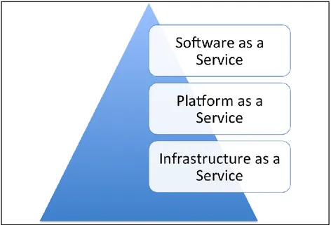
Figure 1.3 illustrates the service model of Cloud Computing. This model consists of three layers including Infrastructure as a Service (IaaS), Platform as a Service (PaaS) and Software as a Service (SaaS). Software as a Service (SaaS) or cloud application service delivers software over the Internet. It eliminates the need to install the application on the customer's own computers, simplifies its maintenance and support [8].
managing the underlying hardware and software layers. It hides the complexity and details of infrastructure from users by API (Application and Programming Interface), a simple graphical interface[8].
Infrastructure as a Service (IaaS) or cloud infrastructure service delivers computer infrastructure as a service. Clients don’t need to purchase software; network equipment or data center space and they buy those resources as a fully outsourced service[8].
1.2 Aspects of the problems
Integrating Cloud based IMS and VANETs will open the door to wide range of new multimedia services. Basically it allows the provisioning of new and optimized services with efficient QoS.
To further explain the problem, we could analyze the scenario for the road user who wants to use IP-based multimedia services in his/her car during the trip. For instance, it is possible that road user wants to send instant message to another car or using real-time multimedia services. Because of the characteristics of ad hoc network, providing the real-time services with acceptable QoS for VANET raises a lot of challenges. The current architecture, which uses Road Side Unit (RSU) and centralized architecture, cannot provide road users in VANET with stable, high Internet access and multimedia services. The high-speed nodes in VANETs move in and out of range of RSUs; therefore, the Internet connectivity is not stable and quality of service goes down because of frequency interruptions during handovers between RSUs.
The IMS, which is defined by 3GPP, supports high-speed IP-based data, voice and multimedia services with controlling the QoS. This traditional IMS architecture core network faces the set of problems such as centralized control, low efficiency and poor scalability of core equipment, compared with the IT environment using Cloud Computing.
On the other hand, with advent of Cloud Computing, a lot of services suppliers over the Internet, migrates to Cloud Computing to benefit from the main features of Cloud Computing. In this trend, IMS is not excluded.
Therefore, lack of stable Internet connectivity in VANET to receive multimedia service and inefficient centralized IMS architecture creates major risks in QoS. Up to our knowledge, there is not the architecture to integrate VANET, IMS and Cloud Computing to provide road users in VANET with IMS services.
1.3 Research Objectives
Our main goal is to design and develop an architecture to integrate VANET, IMS and Cloud Computing with appropriate mobile gateway as a middleware. More precisely, this project has the following goals:
1. Propose appropriate mobile gateway located in vehicles in order to meet requirements of IMS, VANETs and Cloud Computing integration;
2. Develop a prototype of the middleware as a proof of concept;
3. Validate the proposed middleware by evaluating and comparing the output results.
1.4 Outline
The rest of this dissertation is organized as follows. The Chapter II presents the state of the art according to the integration of VANET with the Internet services and, more especially, with IMS. In chapter III the proposed architecture is exposed in details. The Chapter IV is devoted to the performance analysis of the proposed architecture. The interaction between VANET and Cloud-Based IMS is also simulated in this chapter. Finally, we conduct the conclusion and the future works.
CHAPTER 2 STATE OF THE ART
This chapter presents the state of the art from different technologies and integrations conceived in this project. In the first section, we will explain VANETs and consider different aspects of this network. Secondly, we will explain and describe IMS architecture in detail. Thereafter, we will present a brief survey on the integrations that have been done between VANETs and IMS framework. Then, in fourth section, we will introduce the IEEE 802.21 standard framework and make clear how this technology can meet the requirements. Later on, the Cloud Computer features along with Cloud based IMS architecture will be presented. Finally, benefits and weakness of the current overlay solution for system integration are presented.
2.1 Vehicular Ad-hoc Network (VANET)
As regards, VANET is designed to improve roadway safety and traffic efficiency, thus it can be considered an important issue for academic and industrial researches[9]. In this section, we present basic concepts on these networks.
2.1.1 Characteristics of VANET
VANET are a subgroup of Mobile Ad hoc Network (MANET). So, VANET inherits many of characteristics of MANET. Furthermore, VANET has some additional specific features including low cost, flexibility, fault tolerance, creating new applications for remote area[10, 11]. Some of these unique characteristics are discussed in the following:
1. High dynamic topology: Topology changes have high frequency in VANETs because
there are variable parameters during the trips of the vehicles such as speed of movement, connection lifetime, choice of path and multi-hop organization. In the other word, these variable factors, which are the unique features in VANET, cause dynamic topology in VANET[10].
2. Frequency disconnected networks: In order to decrease the effect of fading and to perform
seamless connectivity, the time between link disconnection and choosing another link connection should be too short. However, in low-density situation, the problem of disconnection increases. This problem could be solved by using roadsides and relay nodes[1].
3. Mobility modeling and operating environment: In order to obtain efficient connectivity, it is necessary to know the position of nodes and their movement directions to predict the next hop and prevent the link disconnection. This is due to the fact that the VANETs mobility model is limited by plan of roadways. In addition, changing the mobility model (highways or urban environments) can effect on designing the VANET algorithms. Highway mobility model is simple due to one-dimension model. Whereas in urban model, some features like street structure, high node density, two dimension roads, obstacles and interferences via tall buildings and trees in city, must be considered. These features cause to have different and complex design for VANET in urban environments [10, 11].
4. Partitioned networks: Dynamic nature of road traffic creates the gaps between the vehicles' communications and generates isolated node clusters in the roadways[10].
5.Infinite energy supply: Rechargeable batteries can provide road users with sufficient energy and solve the energy constraint problem in VANET[9].
2.1.2 Applications of VANETs
The applications in VANETs are classified in two main categories including safety applications and non-safety applications or user applications[1].
Safety applications provide safety environment in VANET. These applications try to decrease the accident and traffic collisions in roadways, which are important in situations such as accidents, intersections and road congestion. According to high speed of vehicles in roads, drivers cannot react correctly in hazard situations. If the drivers are informed about an accident that can be occurred in front of them, the safety applications can be used to warn vehicles. When vehicles receive some emergency messages from safety applications, they can reduce the speed before they approached to the accident, thus it is possible to prevent another accident.
Another group of VANETs' applications are non-safety (user) applications. These kinds of applications are used for providing information about traffic jam, comfort driving and route optimizing.
According to daily requirement of the Internet for peoples who travels with vehicles, non-safety application of VANET must provide seamlessly the Internet connectivity for drivers and passengers. Also peer-to-peer applications have been employed for file sharing or playing game between vehicular users [4, 10].
2.1.3 Architecture of VANET
System architecture of VANETs composed of various components, which are depicted in figure 2.1. Three district domains can be considered for VANETs architecture. In-vehicle domain consists of On-Board Unit (OBU); each vehicle is equipped with this unit. The OBU provides short-range wireless communication for safety and non-safety communications. The ad hoc domain is formed of OBUs and Road-side Units (RSUs). One mobile ad hoc network can be considered between OBUs that makes inter-vehicle communications for peer-to-peer and safety broadcasting. OBUs communications are one hop or multi-hop regarding to communication generator application.
Finally, infrastructure domain consists of RSU and Hotspots (HS) that is used for accessing to safety and non-safety applications. RSUs provide the Internet access, while HS is considered for less controlled environments. In addition, if the Internet access cannot provide by RSUs or HSs, thus OBUs can use integrated cellular network capabilities (e.g. GSM, GPRS, UMTS, HSDPA, WiMAX, 4G) for the Internet usage.
2.2 IP Multimedia Subsystem (IMS)
As mentioned before, IMS is the key element in 3G architecture. Although all the Internet services are usable and available for 3G users via packet-switched domain, we need IMS in order to ensure Quality-of-Service, manage charging and integrate different services. Therefore, the following requirements should be considered in IMS framework[2]:
Support for establishing IP Multimedia Sessions, which means to support multimedia sessions over packet-switched network
A mechanism to support Quality-of-Service.
Support interworking with the other networks, which means to be able to support heterogeneous network.
Support for roaming
A service control to charging mechanism
Support for secure communication
In this part, we explain how the architecture and IP-based protocols of this subsystem support and provide above requirements. IMS is an overlay control layer above the IP layer[13].
Figure 2.2.Multimedia Subsystem (IMS) CORE [6]
As shown in Figure 2.2, there are four layers in architecture of IMS. The device layer includes all the mobile and fix devices. The transport layer is responsible for initiating and terminating SIP session and providing conversion of data. In the control layer Call/Session Control Function (CSCE) and Home Subscriber Server (HSS) are the essential nodes in IMS Architecture. CSCF are composed of the set of SIP servers processing SIP signalling. On top of the control layer, we can see the service layer. This layer presents all the services, which are provided by the IMS.
IMS core network consists of nodes, which are classified in three groups, including databases, SIP servers and Application servers. Figure 2.3 shows the relation among these three groups.
Figure 2.3.The relation among SIP servers and HSS
In the first group, the Home Subscriber Server (HSS) and the Subscription Locator Function (SLF) are two databases in IMS architecture. HSS and SLF are using as central repository for user-related information and mapping user address respectively. The former is the master database for given user. It contains the user identities, registration information, access parameters and the other subscription-related information to support network entities and handle calls/sessions.
The later one is necessary if the network has more than on HSS. In fact, SLF maps address of users to HSS. It gets the user, address as input and then it finds which HSS contains the relevant information about that user.
The second group can be considered as SIP servers. These SIP servers, collectively called Call Session Control Functions (CSCFs), are essential nodes in IMS. They play important rule to process SIP signalling packet in IMS. Each individual CSCF node has three important entities including P-CSCF, I-CSCF and S-CSCF.
1. Proxy-CSCF (P-CSCF): It is the first point of contact with IMS terminal. All the requests sent from IMS user traverse this entity. THIS sip proxy forwards SIP requests and
responses in the appropriate direction. Before registration, the P-CSCF is assigned to IMS terminal and it does not change during the call session. The user authentication,
DIAMETER UAR/UAA DIAMETER MAR/MAA SIP 401Unauthorized SIP
Register RegisterSIP
P-CSCF S-CSCF
I-CSCF
HSS
SIP Register
on underlying packet network, this entity usually is located either in home network or visited network.
2. Serving –CSCE (S-CSCF): When a subscriber enters the network, subscriber has the user location (e.g., the IP address of the terminal the user is logged onto) and the user’ SIP address (also known as Public User Identity). The main rule of S-CSCF is to bind these two addresses in order to session control. This entity is enabling to inspects SIP message, forbid unauthorized operations, provide SIP routing service. Because of interfaces between S-CSCF and HSS, user profile in HSS including set of triggers causes SIP messages to be routed to appropriate application server.
3. Interrogating-CSCF (I-CSCF): Interrogates HSS in order to obtain the address of relevant S-CSCF because each IMS core can have several S_CSCF. This entity also has interface with Application server in order to address the requests for services.
Application Servers are located in third and last group. It provides value-added multimedia services. This entity has interfaces with the other SIP sever as mentioned above. This entity process incoming SIP session, generate SIP request and send accounting information to the charging function.
2.2.1 IMS and Protocols
The protocols play important role to control user session in IMS. All these protocols are based on IP. One, which is proposed by IETF, is SIP (Session Initiation Protocol) protocol. This protocol is chosen by 3GPP in order to establish and manage multimedia session over IP Networks. SIP inherits the most of its characteristic from HTTP and SMTP, which are the most successful protocols in the Internet; therefore, like HTTP and SMTP, this protocol is text-based. This means that it is easier to debug, extend and build new services.
As mentioned above, like HTTP, SIP is based on request/response transaction and each request invokes particular procedure on SIP servers. As shown in Figure 2.4, each SIP messages (INVITE, SUBSCRIBE…) from the user agent is forwarded to P-CSCF.
Figure 2.4. Registration at IMS level[2]
The SIP register messages are always sent to the I-CSCF. This entity can query HSS in order to find relevant S-CSCF to forward the request to. Then, S-CSCF manages the user after successful authentication by HSS. According to user profile, S-CSCF forwards the request of the user agent to application server depending on the different service subscribed by the user.
The mobile IMS terminal, which is in our case the mobile node in VANETs, must be re-registered each time it changes its IP address or change access point. For this purpose, it should re-invite the correspondent node.
2.2.2 Presence Framework of IMS
The presence service of IMS allows an entity to share some information about its situation, position, reachability, availability, and willingness of communication with another entities. It can provide an extensive amount of information about a person to a set of interested users. Even more, services are able to read and analyze this information to provide further services.
status, capabilities and location). It has several Presence User Agents (PUAs), which provide this information to the Presence Service. Each PUA can collect different pieces of information. Presence Agent (PA) - It gathers information sent by the PUAs and obtains an idea of the user’s presence.
Presence Server - It is a functional entity that acts as either a PA, as proxy server for SUBSCRIBE requests or as both. In IMS, this entity is represented as an Application Server that acts as a PA.
Watcher - It refers the user that requests presence information from presentity.
It is built on top of the SIP event notification framework; which is based in SUBSCRIBE/NOTIFY requests. A watcher subscribes to receive information from a presentity for a period of time or for requesting some specific information. The presentity’s PA will send the information to the watchers using a SIP NOTIFY request. Presence information is sent in the body of the messages and it is a XML document called PIDF. The PIDF carries the semantics of presence information between presence entities or roles. It is protocol independent and highly flexible; in fact some extensions have already been proposed to overcome some limitations.
Presence service is divided in three processes. The first one is the publication process where presentity’s PUAs send PIDF documents in a SIP PUBLISH message. IMS CSCFs forward the request to the Application Server that represents the Presence Server; which finally replies with an OK. The second process consists in the subscription of watchers. Through SIP SUBSCRIBE transaction, watchers request to receive information from presentity, watchers can be users or even other services. Once new information reaches the Presence Server a SIP NOTIFY is sent to subscribed users and services that can exploit the information[14].
2.2.3 IMS in Third Generation (3G) and Fourth Generation (4G)
The Third Generation (3G) or International Mobile Telecommunications-2000 (IMT-2000) is a generation for mobile phones and mobile communication. This technology permits to mobile phone users to use audio, graphics and video applications.3GPP (Third Generation Partnership project) and 3GPP2 (Third Generation Partnership Project 2) are two of standard bodies involved in IMT-2000.Both 3GPP and 3GPP 2 have standardized their own IMS. The 3GPP IMS and
3GPP2 IMS use Internet protocol and collaborate with IETF (Internet Engineering Task Force)[2]. In Figure 2.5, we can have an overview of the IMS architecture, which is provided by 3GPP.
Figure 2.5 .3GPP IMS architecture overview
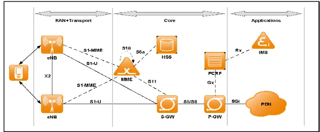
In order to eliminate the weaknesses of 3G of mobile networks, The Fourth Generation (4G) of mobile network was introduced. This generation provides fast access to services, minimized latency and round trip delay, network architecture to match with high bit rate radio and low cost. Figure 2.6 illustrates the architecture of IMS in 4G. As we can see in figure 2.6, the 4G networks splits in three parts including Access Network and Transport Network, Evolved Packet Core (EPC) and Applications.
architecture. This replacement causes the connection to speed up and reduce the time required for handover.
The connection set-up time in real time data session like on-line gaming is important for user. Also, the handover time plays important role in quality of real-time services where end-users the end-to-end calls if the handover takes too long. The EPC is purely IP- based. Real-time and datacom services support the IP protocol.
The International Telecommunications Union-Radio Standardization Sector (ITU-R) targets peak data rates of about 100 Mb/s at speeds of up to 250 Km/H and Gb/s for low mobility access (pedestrian speed or fixed). The IEEE defines new framework to meet these requirements. In fact, integrating of IEEE 802.16 (WiMAX) with 100 Mb/s data rate at 250 km/h and IEEE 802.11 (Wi-Fi) with 1Gb/s at stationary or pedestrian is suitable solution to meet necessary requirements in 4G.
2.3 IMS and VANET integration review
In this section we are going to explain in details the integration available methods between IMS and VANETs.
As we mentioned above, it is desirable to provide road users with the Internet access in VANETs. In order to provide road user with the Internet services, each node in VANETs should communicate with RSU as stationary gateway [15].The communication range of stationary gateway cannot support vehicles with high speed because vehicles quickly move into and out of the communication range of the gateway. Thus, mobile gateways are taken into account in order to eliminate the limitation of stationary gateways [16].In this approach, the mobile gateway is embedded in the vehicle on the road which directly communicates to RSUs and other vehicles. Reference [17] presents the model for integrating VANETs and 3G technology. In this study, vehicles are clustered according to their velocity, their direction and inter-vehicle distances. In this scenario, vehicles are classified into Gateway Candidates (GWCs) and Ordinary Vehicles (OVs) based on using the Universal Terrestrial Radio Access Network (UTRAN) interface. Among the gateway candidates, a minimum number of Cluster Heads (CHs) are chosen as optimal gateway in each cluster. VANETs is linked to UMTS through these optimal gateways. In
this scenario, we can see that, the gateway management is consisted of mobile gateway selection, gateway handover and gateway discovery/advertisement. In all the above cases mobility management is based on Mobile IP protocol, which is in network layer in OSI model. According to basic from [18] and [19], Mobile IP has some limitations including triangle routing , triangle registration, encapsulation overhead and need for home address. Although in IPv6 some problems are eliminated, we can see considerable delay in real-time multimedia services. Because of packets routing mechanism, triangular routing is formed among Home Agent, correspondent node and mobile node. In this process, updating the binding and tunnelling through Home Agent increase the hand-off delays[20]. Moreover, due to data encapsulation in Mobile IP and additional 16-byte address (the Home Address destination address) the payload should tend to decrease. Thus, significant low bit rate packet voice is causes by that. With advent of the IMS, the new doors open to VANETs world. The author in [21] justified the need of this integration. In fact, the real-time communication between vehicles, Session establishing with QoS, geographical position independency are the benefits of IMS and VANETs integration. m:Vía[22] designed an OBU in order to connect the vehicle to IMS through RSU. This on-board gateway has two main part including Application Unit (AU) and Back-end API for communication management. In [23] , a Back to Back User Agent (B2BUA) provides different SIP user agent in the vehicles. This unit is embedded in gateway. Also, in this article SIP protocol manages the mobility instead Mobile IP. According to characteristics of VANETs, each vehicle, which is equipped with OBU, moves between RSU with high speed. It causes frequently handover between RSUs. When the vehicle leaves the current RUS, the vehicle should cooperate with the current RSU and get the list of detected RSUs and the signal rate. Then, vehicle compares the strength of the signal and chooses the next possible one, depends on the direction and speed of the vehicle. All these scenarios result in considerable handover and it is possible that the user loses his/her connectivity with multimedia services.
2.3.1 Media Independent Handover (MIH)
Generally, this framework consists of three main elements including MIH function (MIHF), Service access point (SAPs) and MIH user. In the following Section, we introduce these elements and structure of them in MIH. Figure 2.7 illustrates the elements of MIH and the relation between them. Also, we can see the collaboration with them in order to improve handover functionality.
IEEE 802.21 defines specific services in order to facilitate the handover mechanism. In this part, we discuss responsibility and services of each element in MIH. Figure 2.7 illustrates the elements of MIH.
1.MIH function (MIHF):
The MIHF abstracts lower layer from upper layer. It obtains information from lower layer and transfer appropriate information, event or command to upper layer. It supports remote communication, which is occurred between to MIHF entities.
This element provides three different services in MIH. These Services play vital role in enabling handover. The first service, Media-Independent Event Service (MIES), reports link layer triggers. In fact, this service, according to signal strength (e.g. link-up or link- down) and any other changes in link layer properties, creates event (Link Event) and send it to MIHF. Also, it is possible that this service receives events From MIHF (MIHF Events).
The second one is Media-Independent Command Service (MICS). This service provides local and remote MIH users with set of commands. These commands are used to control and manage different link interface. The initiating of handover and querying of the target networks is preformed by this service. Remote commands are transferred with MIH protocol messages. Like events, commands can be exchanged between lower layer and MIHF and vise versa. The other service is the Media-Independent information service (MIIS). This service provides MIH framework with the information about heterogeneous neighboring networks, their topology, properties and their available services. This element prepares MIH to make decision for performing handover. The MIIS collects relevant information about networks in specific geographical area. This information is useful in order to make decision and execute effective handover.
Figure 2.7. Communication between local and remote MIH entities[24] 2. Service Access points (SAPs):
This service provides MIHF with different access point in order to communicate with lower layer and upper layer. The former is named MIH_SAP provides a uniform interface for upper layers and monitor different links regardless of access technology. The later, which is named MIH_LINK_SAP, controls and monitors media link.
3. MIH user:
The MIH user can employ the all above entities.
2.4 Cloud Computing
As we observe in chapter one, Cloud Computing refers to application and services that run on distributed network while using virtualized resources and accessed by common Internet protocols. In fact, the use of the word ”Cloud” makes reference to two essential concepts: Abstraction and virtualization. In this section we learn more about Cloud computing.
Cloud Computing is separated into two distinct model including Service Model and Deployment Model [25]. Figure 2.8 shows the deployment model. The NIST defines Deployment Model As following:
Public Cloud: The Public Cloud infrastructure is owned by an organization selling Cloud services to general public
Private Cloud: The Private Cloud infrastructure is operated solely for one organization. A Private Clout is distinguished from traditional data center by technical improvements such as high availability and on-demand resources.
Community Cloud: The Community Cloud infrastructure is deployed to serve services to several organizations.
Hybrid Cloud: The Hybrid Cloud infrastructure combines two or more types of Cloud, such as private, public or community while each unit retains its identity in order to enable data and application portability.
Figure 2.8.Deployment Model[26] Also, we can consider the Service Model as following:
Infrastructure as a Service: IaaS provides virtual machine, virtual storage and other resources.
Platform as a Service: PaaS provides a model in order to abstract applications and services from implementation. A PaaS adds integration features, middleware and other services to the IaaS.
Software as a Service: SaaS provides the access to software remotely as a web-based service.
Based on Figure 2.9 Called the Cloud Reference Model, we can observe that in the bottom of stack is hardware and resources. As you go up in the stack, it seams that each layer inherits the characteristics of underlying layer. In this model, the presence of middleware abstracts the structure of IaaS from SaaS.
Figure 2.9.Cloud Computing Reference Model [3]
2.5 IMS and Cloud Computing
These days, IP Multimedia Subsystem provides many users with new services and applications. It causes the IMS to gain more and more interests from industry. By increase of IMS service demand, the traditional IMS infrastructure faces to set of problems. In traditional
dedicated hardware and costs a lot[27]. Thus the performance of such system falls down, especially compared with the IT environment using Cloud Computing. The Cloud Computing offers high scalability and availability. So, the author in [28] has tendency to integrates Cloud Computing services into IMS network. The author presents IMS Cloud QoS system architecture, in which the lower layer (IaaS) is the development platform used for binding IMS with heterogeneous networks such as UMTS, WLAN and WiMax through IMS QoS policy. In this model, PaaS presents a platform for system administrator to develop Hadhoop technology needed for distributed file system and MapReduce technology. Finally, the SaaS provides the users with information and services via Cloud Computing system.
This proposal could be adapted to our case where the road user access IMS services through Cloud Computing.
Now that we have described methods to integrate VANETS, IMS and Cloud computing, we could say that the appropriate middleware design in Cloud Computing architecture is acceptable solution to support road users in VANETs with high Quality of Service.
CHAPTER 3 PROPOSED ARCHITECTURE
As many users spend long times in their vehicles, it will be interesting to provide them with IMS services in their cars. Giving access to the IMS through VANET connectivity will be an evolution of VANET. This chapter proposes a new architecture to integrate VANET and Cloud based IMS. Firstly, the design and basis of the proposal are explained. This part includes assumptions, principles, elements and topology of the architecture. Later on, the rules, which govern the architecture, are described. The information model, the protocol and the procedures are also presented. Finally, the scenario using the proposed architecture is explored.
3.1 Proposed Architecture
VANET is highly dynamic ad hoc network with restricted access to the network infrastructure. Therefore, it is hard to maintain ubiquitous connectivity and guarantee acceptable QoS in terms of data loss, jitter and latency during the handover of vehicles from one network to another one. On the other hand, ubiquitous connectivity should be provided in secure situation with acceptable QoS. It is necessary to support vehicle with authentication, confidentiality and integrity during data transferring with the other vehicles and network infrastructure. In this proposed architecture, to provide vehicles with multimedia services, we choose IMS infrastructure. The reasons of this choice are as follows:
1. VANET can benefit from different technologies to access to a network infrastructure such as Wi-Fi, 3G and LTE. IMS can support network heterogeneity.
2. IMS enables communication between vehicles in real-time with QoS parameters, as well as provides vehicles with new integrated QoS-gauranteed multimedia services. This happens, independently from geographical location of vehicles. For instance, SIP could be used as mobility management protocol and QoS infrastructure of IMS.
3. It is well-known that authentication and authorization are very critical and mandatory in VANET. IMS provides maximum security through reliable authentication and authorization of users. It can be based on widely used protocols such as SIP, SDP, RTP and Diameter. The identities are managed through Universal Resource Identifier (URI). All of these are supported in IMS infrastructure.
networks and low throughput.
Cloud Computing service provider can support their customers with more reliable and available services such as multimedia services. Service providers are able to use resource pooling to enhance their services. The advantage is to offer cheaper services with more quality and performance. «Cloudifying» the network elements of the IMS framework in order to take advantage of key benefits of the cloud like elasticity and the utility style pricing, is the other goal of this proposed architecture. We can follow the benefits of cloud deployment for the IMS:
1. Enable the users of IMS to benefit of high speed and imaginative new service that combine voice, data, video and mobility.
2. Enable the service provider to be away with Capital Expenditure involved in buying the software and hardware for CSCF.
3. Enable the service provider to start with small deployment and grow based on number of subscribers and network traffic.
In this chapter, we propose the mobile gateway as a simple and straightforward solution to provide VANET with multimedia services in Cloud Computing through the IMS. This gateway should be able to communicate with service provider in Cloud and VANET directly. This can be executed by the middleware and processing entities found within the architecture of the gateway. Therefore, the gateway should be able to publish VANET information to service provider who supports the road users of VANETs with IMS services in Cloud Computing. Moreover, we will present a new architecture for Cloud provider. In this architecture, Cloud provider deploys the IMS core network and special application servers to provide the road users in VANET with multimedia services. The Cloud provider deploys IMS infrastructure as a new service to support the end user with higher QoS.
We propose a gateway architecture and Cloud based IMS architecture to fulfill the defined needs and we design the solution from this decision. Following the detailed presentation of the architecture, an analysis on how the requirements are met by the proposal will be done in chapter IV.
3.2 Assumption
Our idea is to provide a gateway to interconnect Cloud based IMS and VANET. We assume that all entities of the system (i.e. VANET, gateway and IMS) are configured to know each other. Additionally, we assume that all mobile nodes (i.e. Vehicles) in are equipped with mobile gateways. The mobile gateway is capable to communicate to 4G-backhaul networks via appropriate network interface. Vehicles can also move in different directions with different speeds.
However, the design of the architecture ensures that minimal changes and adjustments could be made such as the format changes.
3.3 Architecture Principles
The principles of our architecture are based on three layers including device layer, transport layer and service layer. The figure 3.1 illustrates the general architecture.
Figure 3.1. Three-layer IMS based Cloud Services general architecture
The general architecture (Figure 3.1) indicates a novel three-tier Cloud Based IMS architecture for VANET from functioning point of view. By integrating VANET, IMS and Cloud Computing techniques, we aim to provide the users with: (i) real-time services with high QoS, (ii) sharing and cheap services. The vehicles, which are equipped with mobile gateway, belong to
Device Layer MOBILE CAR GATEWAY Communication Layer E node B E node B
Service Layer (IMS core network and Application Server in Cloud)
IMS CORE NETWORK
APPLICATION SERVERS
The mobile gateway of vehicle can connect to the IP network in the transport layer via a variety of transmission media, including Wi-Fi (a wireless local area networks technology), 3G and 4G. In this architecture, we choose enode B as base station to connect vehicles to 4G networks.
All the vehicles classified in first layer can communicate via second layer with cloud based IMS core network in third layer. All the Cloud services which road users are subscribed to are available through the IMS core network. In fact, this core network controls and manages all the data transaction between application servers in cloud and road users in VANET.
To meet above requirements in our architecture, we focus on device and service layers of our architecture. The existence of mobile gateway in device layer is very important because via this gateway the users can communicate to service layer to benefit from multimedia services. On the other hand, to improve the quality of multimedia services, we need novel architecture based on Cloud Computing and IMS that is proposed in service layer of our architecture. Firstly, we explain the topology of our mobile gateway in first layer. After that, we present appropriate architecture for cloud provider providing multimedia services to road users in VANET while using IMS core network.
3.4 Architecture topology and interactions
As depicted in figure 3.2, first, the service provider of IMS services in Cloud has to authorize the end user to use the services. This typically requires a subscription or contract between the service provider and end user in VANET. Then, in second step, the vehicle equipped with mobile gateway requires registering with service provider to authentication, authorization and accounting. In fact, service provider has to know which services and level of QoS the end user subscribes to. In this case, service provider deploys the IMS core infrastructure as a service to manage and control the session as well as user authorization and authentication. Afterwards, in third and forth step, the vehicle sends request and receives the service from service provider in cloud, respectively.
Figure 3.2. Prerequisites to get IMS services in Cloud
Figure 3.3 presents the topology of three-layer architecture components. Vehicle is equipped with a gateway. The Cloud provider enables IMS services to Vehicles.
Figure 3.3. Architecture topology
In the first layer of proposed three-layer architecture, there are some nodes of VANET, which are equipped with On-Board Unit (OBU). The OBU interacts with the mobile gateway. It is assumed that OBU is equipped with Application Unit (AU), dual interfaces of IEEE 802.11p and the 4G networks, GPS devices, and also experiencing different 4G-signal strength intensities at different regions. The AU of the OBU can determine a set of communication parameters (i.e.
Hardware Hypervisor
Mobile Gateway
E Node B
Evolved Packet Core Network (EPC) IMS Servers Virtual Machine VANET Server Virtual Machine Application Servers Virtual Machine Cloud Provider Architecture
Middleware
Network Interfaces
1.Establishment of an IMS service contract with service provider in Cloud
2. Registration with Service Provider
3. Send IMS service request to Service Provider
4. Receive the Service from the Provider
IMS service provider in Cloud Vehicles As IMS Terminal
communication channel is created, the driver and passengers can get relevant services. The OBU is capable to report to the Mobile Gateway, the situation of the vehicle such as the available bandwidth. A mobile gateway refers to the dual-interfaced vehicle that relays data from VANET to the Cloud Based IMS architecture. It is equipped with dual interfaces of IEEE 802.11p and the 4G networks. Therefore, the gateway can report information to the service provider in Cloud. Both the mobile gateway and OBU can communicate with Evolved Node Bs (eNodeBs). These base stations through Evolved Packet Core Network (EPC) connect to the cloud. To meet the requirements of our architecture, this proposed mobile gateway has two main tiers. (These tiers will be discussed in 3.4.1 section in details). Bellow, we can follow these tiers of the gateway briefly:
1. Middleware Tier: this unit processes the received information and depends on them. It stores, compares and distributes information among another units.
2. Network access: There are two network access interfaces in this tier to communicate with VANET and 4G.
The second layer of the proposed three-layer architecture is the communication layer. The main element in this layer is 4G networks. The main motivation in IMT-Advanced (4G) networks is higher data rate to deliver wireless services competitive with broadband wire line. To achieve this goal, two radio accesses technologies IEEE 802.11 (1 Gb/s, low velocity) and IEEE 802.16 (100 Mb/s, 250 Km/h) are combined to introduce emerging IEEE standard for media independent handover services named IEEE 802.21. This new standard supports seamless mobility between two radio access technologies. The 4G networks can coordinate with nodes in VANET to deliver higher data rates wireless services.
The third layer of the proposed three-layer architecture is the service layer. In this layer, the IMS core network is deployed as new services in order to provide VANET with multimedia services. As shown in figure 3.4, IMS core network infrastructure, VAVET Server and Application Server are considered as services, which are provided by cloud provider. They are executed on virtual machines in Cloud Computing. These servers handle all the information received from vehicle, manage the mobility in application layer when session is established to provide the multimedia services.
A Proxy Call Server Control Function (P-CSCF), Interrogating Call Server Control Function (I-CSCF), Serving Call Server Control Function (S-CSCF) and Home Subscriber Service (HSS) constitute the IMS core network. All the SIP messages from the road users (such as INVITE, REGISTER, SUBSCRIBE) should pass via the P-CSCF to reach the IMS core as new service in Cloud Computing.
Figure 3.4. The Cloud Services
The P-CSCF forwards the road user SIP request to the appropriate I/S-CSCF depending on certain information obtained from HSS. After successful authentication and authorization, the road users receive the requested services from IMS core network.
Besides the IMS core network, there are two main servers in this layer. The VANET server, which acts as the presence server, keeps the presence information of the vehicles. This server has an interface with S-CSCF. The S-CSCF forwards the related messages from road user to this server. It also passes messages from VANET server to road users. The Video Streamer Server has an interface with S-CSCF in order to get status information of the vehicles subscribed from VANET Server to them. When the VANET Server receives new published message from the vehicle, it notifies the application servers subscribing to that vehicle through S-CSCF.
To provide the communication among road user, VANET Server and AS, we utilize Session Initiation Protocol (SIP), SUBSCRIBE, NOTIFY and PUBLISH messages defining by Internet Engineering Task Force (IETF) SIP for Instant Messaging and Presence Leveraging extension (SIMPLE) working group.
3.4.1 Roles of defined Units in Gateway Architecture
The proposed gateway has two main tiers. Each tier consists of components and has specific roles. In following, we consider the roles of each tier.
Access Network E Node B Car Gateway Cloud Computing P-CSCF I-CSCF S-CSCF VANET Server Video Streamer HSS
on SIP messages. The Presence Manage Unit (PMU) is an entity that accepts, stores and publishes presence information of the vehicles based on SIP protocols. This unit manages presence state (and location) publication from vehicles. It can refresh and replace existing presence information with newly published information. The PMU publishes messages when the situation of the vehicle is changed. The middleware gets information such as available bandwidth, position and signal strength from the third tier. The achieved information is processed and translated to SIP Publish request by the processor and the translator of this tier.
Figure 3.5. The gateway architecture
The third tier is in charge of controlling the access technology. There are two main network interfaces in this tier: Wi-Fi access network interface and 4G back-haul access network interface. The Wi-Fi access network interface is used for communicating with the other vehicles. This tier receives the requests of the other vehicles. Then, the request will be forwarded to middleware for processing and translating. After processing and translating, the middleware prepares the request to send toward Cloud Based IMS. Therefore, middleware retransmits the request to the third tier which is sent to the Cloud Based IMS via 4G interfaces. Also, this tier can provide the middleware with useful information. The middleware uses the information to notify the Servers in Cloud to manage the application bandwidth.
Translator Middleware Storage Processor PMU Access Technologies Wi-Fi 4G
3.4.2 Roles of defined servers in Cloud
In this part, we explain the roles of the servers located in Cloud. As shown in figure 3, IMS Servers (including P-CSCF, I-CSCF and S-CSCF, HSS and SLF databases), VANET Server and Video servers are the main Cloud servers providing services. All these servers are running over the virtual networks in cloud. They are in charge of managing and controlling the SIP session.
All the SIP messages among vehicles and Servers in Cloud Computing Architecture are routed through the IMS servers in Cloud Computing Architecture. In fact, The IMS core network is laid between access network (4G back-haul network) and application servers in Cloud Computing. In this architecture, we can use the features of IMS core network to control security and QoS of established SIP session.
In this architecture, VANET Server acts as Presence Server in IMS. However, this server has just handled the SIP messages between vehicles and application server in Cloud. VANET Server provides application servers with presentity’s information of vehicles. To provide the presentity information of vehicle to VANET server, we utilize the SIP Subscribe, Notify, and Publish messages defined by Internet Engineering Task Force (IETF) SIP for Instant Message and Presence Leveraging Extension (SIMPLE) working group.
3.4.3 Interactions
In this part, we explain how message exchange and communication will be occurred among between VANETs and cloud provider.
The Scenario
In this scenario, the vehicle equipped with mobile gateways wants to establish the session with Application Server in Cloud based IMS. It is obvious that the road users have contract with service provider to utilize IMS services through Cloud Computing. The vehicles use SIP request to establish SIP session with Application Server in cloud based IMS. All the requests are passed through CSCFs servers to establish, manage and terminate the session. Furthermore, because of high mobility of vehicles in VANET, the vehicle should send periodically their position and available bandwidth with SIP method to VANET Servers. Then, the VANET Server communicates with associated application server to notify the application server about the presentity’s information of the vehicles. VANET server and application servers communicate with each other with SIP protocol via CSCFs servers described in following sessions.
![Figure 1.1.VANETS Structure [5]](https://thumb-eu.123doks.com/thumbv2/123doknet/2345178.34715/16.918.134.783.105.567/figure-vanets-structure.webp)
![Figure 1.2. IMS Architecture[6]](https://thumb-eu.123doks.com/thumbv2/123doknet/2345178.34715/18.918.202.749.103.649/figure-ims-architecture.webp)
![Figure 2.1.VANET system Architecture [12]](https://thumb-eu.123doks.com/thumbv2/123doknet/2345178.34715/24.918.138.792.604.987/figure-vanet-system-architecture.webp)

![Figure 2.4. Registration at IMS level[2]](https://thumb-eu.123doks.com/thumbv2/123doknet/2345178.34715/29.918.138.760.108.611/figure-registration-at-ims-level.webp)
![Figure 2.7. Communication between local and remote MIH entities[24] 2. Service Access points (SAPs):](https://thumb-eu.123doks.com/thumbv2/123doknet/2345178.34715/35.918.138.775.109.538/figure-communication-local-remote-entities-service-access-points.webp)
![Figure 2.8.Deployment Model[26] Also, we can consider the Service Model as following:](https://thumb-eu.123doks.com/thumbv2/123doknet/2345178.34715/36.918.164.742.572.856/figure-deployment-model-consider-service-model-following.webp)
![Figure 2.9.Cloud Computing Reference Model [3]](https://thumb-eu.123doks.com/thumbv2/123doknet/2345178.34715/37.918.105.779.413.860/figure-cloud-computing-reference-model.webp)