UNIVERSITÉ DE MONTRÉAL
DEVELOPMENT OF GRAPHENE-BASED POLYMER NANOCOMPOSITES FOR ELECTRICAL CONDUCTORS AND SUPERCAPACITORS
ALI MOAYERI
DÉPARTEMENT DE GÉNIE CHIMIQUE ÉCOLE POLYTECHNIQUE DE MONTRÉAL
THÈSE PRÉSENTÉE EN VUE DE L’OBTENTION DU DIPLÔME DE PHILOSOPHIÆ DOCTOR
(GÉNIE CHIMIQUE) DÉCEMBRE 2015
UNIVERSITÉ DE MONTRÉAL
ÉCOLE POLYTECHNIQUE DE MONTRÉAL
Cette thèse intitulée:
DEVELOPMENT OF GRAPHENE-BASED POLYMER NANOCOMPOSITES FOR ELECTRICAL CONDUCTORS AND SUPERCAPACITORS
présentée par : MOAYERI Ali
en vue de l’obtention du diplôme de : Philosophiæ Doctor a été dûment acceptée par le jury d’examen constitué de : M. PERRIER Michel, Ph. D., président
M. AJJI Abdellah, Ph. D., membre et directeur de recherche M. THERRIAULT Daniel, Ph. D., membre
DEDICATION
iv
ACKNOWLEDGEMENTS
I would like to express my everlasting gratitude to my father, Masoud, mother, Haleh, and sister, Valeh, who have always been there for me. Words are powerless to express what I feel in my heart towards them. I send my deepest gratitude to my wife, Kiana, and my newborn daughter, Liana, for being there for me in all the moments. Words are incapable to express what I feel in my heart towards them.
I would like to express the deepest appreciation to my supervisor, Prof. Abdellah Ajji, who is inspiring for me in many aspects, which are not limited to research. His kind consideration, support and affability besides of his guidance in repute to research provided a medium full of spirit of adventure in regard to research and innovation which are much more than what is written in this thesis.
I take this opportunity to place my sincere thanks to all the members of Prof. Ajji’s research group, particularly to Claire Cerclé and Richard Silverwood for their help and support. I would like to express my special thanks to Mounia Arkoun for her help in translating the abstract of this thesis to French.
I would also like to thank the supervisory committee members for their insight and helpful comments, namely Prof. Michel Perrier, Prof. Daniel Therriault and Prof. Nicole R. Demarquette. In addition, I am grateful to all my friends who were there for me during my Ph.D. studies at Polytechnique Montreal. I cannot list them all as it would be a very long list so to anyone who thinks I am his/her friend; I express my deepest gratitude.
I would like to thank Nicole MacDonald and Jean-Philippe Masse from CM2 for their help and assistance with microscopy imaging. I would also like to thank Dr. Josianne Lefebvre for her
guidance and help with the XPS analysis and Dr. Gwenaël Chamoulaud at NanoQAM - Université du Québec à Montréal for his assistance with carbonization process and electrochemical tests. The administrative staff of our department had a significant role in helping us and providing us with a calm atmosphere in order to advance our projects, namely Evelyne Rousseau, Lyne Henley and Carmen Elena Membreno Aguilar.
The financial support from the Natural Science and Engineering Research Council (NSERC) and the Fonds de recherche du Québec – Nature et technologies (FRQNT) is highly appreciated.
vi
RÉSUMÉ
L’électrofilage est une méthode pratique et avantageuse pour obtenir des nanofibres de polymères avec des diamètres contrôlés de l'ordre de quelques dizaines de nanomètres à quelques micromètres. Les mats de fibres non-tissées résultants ont des surfaces spécifiques élevées de l'ordre de 1 à 100 m2/g. La combinaison de ces propriétés avec la conductivité électrique intrinsèquement élevée de certains polymères conducteurs donne lieu à des mats de fibres conducteurs qui sont très prometteurs pour diverses applications dans divers domaines dont : l’électronique, le magnétique, le biomédical, mais encore des applications en optique et dans le domaine des capteurs.
Une nouvelle classe de polymère connue sous le nom de polymères intrinsèquement conducteurs (PIC) a été découverte en 1960. Les PIC sont de nature intrinsèquement conducteurs en raison de la présence d'un système d'électrons π conjugué dans leur structure. Les PIC possèdent des bonnes propriétés électroniques, des faibles potentiels d'ionisation et une électroaffinité élevée. La polyaniline (PANi) est l'un des PIC les plus étudiés. Elle est unique en raison de la facilité de sa synthèse, de sa stabilité environnementale et de la simplicité de sa chimie de dopage/dédopage. En revanche, elle est relativement difficile à mettre en forme par rapport à la plupart des autres polymères conventionnels, ce qui est typique des PIC. En effet, la polyaniline a un squelette assez rigide en raison de son aromaticité élevée. Ainsi, l'élasticité des solutions de PANi est généralement insuffisante pour qu'elles puissent être électrofilées pour en faire des nanofibres. En outre, la PANi a une mauvaise solubilité dans la plupart des solvants communs, ce qui rend son électrofilabilité encore plus difficile. Cependant, si les limitations de solubilité et de rigidité suscitées pouvaient être résolues, la PANi pourrait être électrofilée en mats de fibres conductrices pouvant être utilisés
dans une large gamme d'applications telles que les capteurs chimio-résistants, les surfaces hydrophobes réversibles et les substrats pour la fonctionnalisation.
Le but ultime de la première partie de cette thèse est de préparer des nanofibres de PANi électrofilées avec du graphène intégré pour une utilisation potentielle comme capteurs pour la détection de gaz et de pathogènes. À cette fin, deux stratégies ont été utilisées pour obtenir les nanofibres électrofilées de PANi:
Mélanger de la PANi dopée avec des polymères isolants et facilement électrofilables comme le poly(oxyde d’éthylène) ou PEO. Cependant, la présence du polymère isolant réduit la conductivité des fibres en raison de la diminution des composés conducteurs dans le mélange. Une bonne stratégie pour compenser l'addition du polymère isolant et améliorer les propriétés électriques globales des fibres électrofilées, est d’y incorporer des nanocharges conductrices à base de carbone. À cet effet, le graphène a été sélectionné. Depuis sa découverte en 2004, le graphène a suscité un intérêt considérable en recherche. Il est constitué d’un simple feuillet d’une seule épaisseur en deux dimensions, lui-même composé d'atomes de carbone organisés en une structure cristalline en nid d'abeilles. Il possède une surface, une résistance ainsi qu’une conductivité thermique et électrique exceptionnellement élevées.
Par conséquent, compte tenu des excellentes propriétés du graphène et de la PANi, des nanofibres de PANi contenant des nanocharges de graphène comme agent de remplissage peuvent être obtenues. Ainsi, des nanofibres conductrices de PANi dopée avec de l'acide camphre-10-sulfonique (ACS), mélangée à du PEO et remplie avec du graphène fonctionnalisé ester succinimidyle de l'acide 1-pyrènebutanoïque ou (G-PBASE) ont été préparées par électrofilage. La microscopie électronique à balayage (MEB), la microscopie électronique à transmission (MET), la spectroscopie de photoélectrons par rayons X (XPS), la spectroscopie infrarouge à transformée de
viii Fourier (FTIR) et l’analyse thermogravimétrique (TGA) ont été utilisées pour caractériser la morphologie des fibres de PANi/PEO/G-PBASE ainsi que leurs propriétés. Les observations montrent que les fibres électrofilées sont fortement interconnectées et possèdent une surface relativement lisse. Le diamètre moyen des fibres est d'environ 220 nm. La conductivité électrique des fibres de PANi/PEO et PANi/PEO/G-PBASE à température ambiante a également été étudiée. Les fibres composites nanostructurées PANi/PEO/G-PBASE avec une faible charge de G-PBASE (5 % en poids par rapport à la PANi) a montré une augmentation de la conductivité électrique de deux ordres de grandeur et une amélioration d’un ordre de grandeur de la stabilité thermique en comparaison avec les nanofibres de PANi/PEO.
Utiliser la technique d'électrofilage coaxial pour préparer des nanofibres structurées en cœur-enveloppe avec la PANi au centre de la fibre et un polymère facilement électrofilable tel que le poly(méthacrylate de méthyle) (PMMA). Par la suite, l’enveloppe externe a été retirée par extraction-solvant pour obtenir des nanofibres de PANi pures. La méthode d'électrofilage coaxial constitue une alternative et un moyen efficace pour l’obtention de fibres de polymères non-électrofilables. Dans cette technique, deux solutions différentes sont électrofilées simultanément à travers une filière composée de deux capillaires coaxiaux pour produire des nanofibres structurées en cœur-enveloppe avec le polymère non-électrofilable au centre de la fibre. Par conséquent, des nanofibres cœur-enveloppe de PANi/PMMA contenant du G-PBASE sont préparées par électrofilage coaxial, avec la PANi et le G-PBASE étant au cœur des fibres et le PMMA l'enveloppe externe, respectivement. Les nanofibres de PANi/G-PBASE/PMMA obtenues possèdent des diamètres de ~420 nm. En outre, des nanofibres de pure PANi et de PANi/G-PBASE ont été obtenues par extraction-solvant de l’enveloppe de PMMA, ce qui a réduit le diamètre des fibres à
230 nm. La morphologie des nanofibres a été analysée par MEB et MET. La structure cœur-enveloppe et l'existence de feuillets de graphène dans la couche centrale des fibres ont été confirmées par les images en MET, obtenues avant et après extraction-solvant du PMMA. La conductivité électrique des fibres obtenues à température ambiante a été étudiée par la méthode de la sonde à quatre points. Les nanofibres de PANi/G-PBASE ont montré une conductivité électrique de 30,25 S/cm, laquelle est trois fois plus élevée que celle des nanofibres de PANi pure.
Dans la deuxième partie de cette thèse, nous investiguons l'ajout de graphène à du polyacrylonitrile (PAN) renforcé par des nanofibres de carbone (NFC). L’objectif étant d'améliorer la surface spécifique et la capacitance des fibres obtenues, en vue d’applications où une densité de haute énergie est requise, tel que dans les supercondensateurs. Récemment, beaucoup de recherches ont été menées sur des matériaux à base de PAN et NFC pour des applications de stockage d'énergie. Cependant, la faible conductivité et densité de puissance des NFC représentent un obstacle à leur utilisation potentielle dans les supercondensateurs. Par conséquent, dans cette étude, des NFC électrofilées en structure cœur-enveloppe et additionnées de différentes quantités de graphène fonctionnalisé de façon non covalente ont été préparées. La technique employée à cet effet est l'électrofilage à une seule buse en utilisant une solution biphasée de polyacrylonitrile et de polyvinylpyrrolidone (PAN/PVP), avec comme solvant du N,N-diméthylformamide (DMF). La concentration en graphène varie de 0% à 15% en poids (par rapport au PAN). Les nanofibres électrofilées structurées en cœur-enveloppe ont d'abord été stabilisées à 250 °C dans l'air puis, par la suite carbonisées à 850 °C dans une atmosphère sous azote pour produire les NFC. Les fibres ultra-minces résultantes ont des diamètres moyens de l'ordre de 60 à 80 nm. La morphologie et la microstructure des nanofibres ont été caractérisées par SEM, TEM, spectroscopie Raman, XPS et
x BET pour l'adsorption d'azote à 77 K. Après incorporation des nanofeuillets de graphène, les résultats ont montré une augmentation de la surface spécifique et du volume des pores des mats de fibres allant jusqu’à 627 m2 g-1 et 0,35 cm3 g-1, respectivement. La performance électrochimique
des nanocomposites NFC/graphène a été étudiée dans une solution de KOH (6M). Les analyses électrochimiques de ces mêmes nanofibres révèlent une capacitance spécifique maximale de 265 F g-1, après ajout de 10% en poids de nanofeuillets de graphène.
ABSTRACT
Electrospinning is a convenient method to produce polymer nanofibers with controlled diameters on the order of tens of nanometers to micrometers. The resulting non-woven fiber mats have high specific surface areas of around 1−100 m2/g. Combining these properties with the high electrical
conductivity of intrinsically conductive polymers yields conductive electrospun fiber mats that are very promising for a variety of applications such as electronic, magnetic, biomedical, sensor and optical fields.
A new class of polymer known as intrinsically conducting polymers (ICPs) were discovered in 1960. ICPs are intrinsically conducting in nature due to the presence of a conjugated π electron system in their structure. ICPs possess electronic properties, low ionization potentials and a high electroaffinity. Polyaniline (PANi) is one of the most studied ICPs and it is unique due to its ease of synthesis, environmental stability, and simple doping/dedoping chemistry, yet it is relatively hard to process compared to most other polymers. As is common among ICPs, it has a fairly rigid backbone due to its high aromaticity. Thus, the elasticity of its solutions is generally insufficient for it to be electrospun directly into fibers. Moreover, PANi has poor solubility in common solvents, which further complicates it electrospinnability. However, if aforementioned processing limitations of PANi can addressed and it can be electrospun into conductive fiber mats, it can be used for a variety of applications such as chemoresistive sensors, reversible hydrophobic surfaces and substrates for functionalization.
The ultimate purpose of first part of this thesis is to fabricate electrospun PANi nanofibers embedded with graphene for potential sensor applications such as gas and pathogen detection. To this end, two strategies were utilized to electrospin PANi nanofibers:
xii 1) Blending doped-PANi with insulating polymers which are easily electrospinnable such as polyethylene oxide (PEO). However, the presence of the insulator polymer will decrease the fibers conductivity due to a reduction of the conducting component in the blend and a good strategy to compensate for the addition of insulating polymer and to improve the overall electrical properties of the electrospun fibers blend is to incorporate carbon-based conductive nanofillers into the fibers and in this work graphene was selected. Since the discovery of graphene in 2004, it has attracted tremendous research interest. Graphene is a single-atom-thick, two-dimensional sheet of sp2 -hybrized carbon atoms arranged in a honeycomb crystal structure with exceptionally high strength, surface area, thermal conductivity, and electronic conductivity. Therefore, considering the excellent properties of graphene and PANi, highly conductive PANi nanofibers with graphene as nanofiller can be obtained. To this end, conducting nanofibers of PANi doped with camphor-10-sulfonic acid (HCSA), blended with PEO, and filled with 1-pyrenebutanoic acid, succinimidyl ester functionalized graphene (G-PBASE) have been fabricated using electrospinning. Scanning electron microscopy (SEM), transmission electron microscopy (TEM), X-ray photoelectron spectroscopy (XPS), Fourier transforms infrared (FTIR) and thermal gravimetric analyzer (TGA) were utilized to characterize the PANi/PEO/G-PBASE fibers morphology and properties. The observations show that electrospun fibers are highly interconnected and possess a relatively smooth surface. The average diameter of fibers was ~ 220 nm. The electrical conductivity of PANi/PEO and PANi/PEO/G-PBASE at room temperature was also studied. The unique nanostructured composite of PANi/PEO/G-PBASE with small loading of G-PBASE (5 wt.% relative to PANi) showed two order of magnitude enhancement in the electrical conductivity and one order of magnitude enhancement in thermal stability in comparison to PANi/PEO nanofibers.
2) Utilizing coaxial electrospinning technique to produce core−shell structured nanofiber with PANi at the core layer and an easily electrospinnable polymer such as poly(methyl methacrylate) (PMMA) at shell segment. Subsequently, the shell segment was removed by solvent etching to produce pure PANi nanofibers. The coaxial electrospinning method provides an alternative and effective way for fabrication of unspinnable polymer with unique core−shell structured fibers. In this technique, two dissimilar solutions are spun simultaneously through a spinneret composed of two coaxial capillaries to produce core−shell structured nanofibers with unspinable polymer at the core section. Therefore, Core−shell structured PANi/PMMA nanofibers embedded with G-PBASE are produced by a coaxial electrospinning setup. PANi/G-PBASE and PMMA solutions were used as core and shell layer respectively. The as-prepared PANi/G-PBASE/PMMA nanofibers possessed diameters in the range of ~420 nm. Moreover, neat PANi/G-PBASE and PANi nanofibers were obtained by solvent etching of PMMA shell which reduced the fiber diameter to 230 nm. The morphology of the nanofibers was investigated by SEM and TEM. The core−shell structure and the existence of graphene sheets in the core layer were confirmed by TEM images obtained before and after solvent etching of PMMA. The electrical conductivity of the fibers at room temperature was investigated by four-point probe method. The PANi/G-PBASE nanofibers exhibited electrical conductivity as high as of 30.25 S/cm which was 3 times higher than that of neat PANi nanofibers.
The second part of this thesis investigates the addition of graphene to polyacrylonitrile (PAN)-based carbon nanofibers (CNFs) in order to improve their surface area and capacitance for applications where high-energy density is required such as in supercapacitors. Recently, a lot of research has been conducted on PAN-based CNFs for energy storage applications. However, CNFs low conductivity and power density is an obstacle for their potential application in supercapacitors.
xiv Therefore, in this study core–shell structured CNFs embedded with various amounts of non-covalently functionalized graphene were fabricated by single-nozzle electrospinning technique using phase-separated solution of polyacrylonitrile and polyvinylpyrrolidone (PAN/PVP) in N,N-dimethylformamide (DMF). The concentration of graphene varied from 0 wt% to 15 wt% (relative to PAN). These core-shell structured electrospun nanofibers were first stabilized at 250 C in air and consecutively carbonized at 850 C in nitrogen atmosphere to produce CNFs. The resulting ultra-fine fibers have average fiber diameters in the range of 60-80 nm. The morphology and microstructure of the nanofibers were characterized by SEM, TEM, Raman spectroscopy, XPS and BET nitrogen adsorption at 77 K. The result showed that the specific surface area and pore volume of nanofiber mats increased to 627 m2 g−1 and 0.35 cm3 g−1 respectively by embedding graphene
nanosheets. The electrochemical performance of as-synthesized CNF/G nanocomposites was investigated in 6M KOH electrolyte by cyclic voltammetry and galvanostatic charge/discharge. Electrochemical measurements of CNF/G nanofibers exhibited a maximum specific capacitance of 265 F g−1 after addition of 10 wt% graphene nanosheets.
TABLE OF CONTENTS
DEDICATION ... III ACKNOWLEDGEMENTS ... IV RÉSUMÉ ... VI ABSTRACT ... XI TABLE OF CONTENTS ... XV LIST OF TABLES ... XX LIST OF FIGURES ... XXI LIST OF SYMBOLS AND ABBREVIATIONS... XXVICHAPTER 1 INTRODUCTION ... 1
CHAPTER 2 LITERATURE REVIEW ... 5
2.1 Electrospinning ... 5
2.1.1 Single-nozzle electrospinning ... 5
2.1.1.1 Control of Fiber Morphology and Diameter ... 7
2.1.2 Coaxial Electrospinning ... 12
2.1.2.1 Solution concentration ... 14
2.1.2.2 Solution viscosities ... 14
2.1.2.3 Immiscibility of core-shell solutions ... 14
2.1.2.4 Solvent vapor pressure: ... 15
2.1.2.5 Solution conductivity ... 15
2.2 Intrinsically conductive polymers (ICPs) ... 16
2.2.1 Polyaniline (PANi) ... 16
2.3 Carbon nanofibers ... 18
xvi
2.3.2 Preparation of CNFs by electrospinning ... 19
2.3.3 PAN-based carbon nanofibers application in supercapacitors ... 20
2.4 Graphene ... 21
2.4.1 Discovery of Graphene ... 22
2.4.2 Synthesis of Graphene ... 23
2.4.2.1 Micromechanical exfoliation ... 25
2.4.2.2 Chemical Exfoliation of Graphite ... 26
2.4.3 Properties of Graphene ... 30
2.4.3.1 Structure of Graphene ... 30
2.4.3.2 Chemical Properties ... 32
2.4.3.3 Mechanical Properties ... 33
2.5 Graphene-based Polymer Nanocomposites ... 35
2.5.1 Fabrication of Graphene/Polymer Nanocomposites ... 37
2.5.1.1 Solution mixing ... 38
2.5.1.2 Melt Blending ... 39
2.5.1.3 In Situ Polymerization ... 39
2.5.2 Challenges in Fabrication of Graphene/Polymer Nanocomposites... 40
2.6 Summary and problem identification ... 41
2.7 References ... 43
CHAPTER 3 ORIGINALITY AND OBJECTIVES ... 53
3.1 Originality ... 53
3.2 Objectives ... 54
CHAPTER 5 ARTICLE 1: FABRICATION OF POLYANILINE/POLY(ETHYLENE OXIDE)/NON-COVALENTLY FUNCTIONALIZED GRAPHENE NANOFIBERS VIA
ELECTROSPINNING ... 59 5.1 Abstract ... 59 5.2 Introduction ... 59 5.3 Experimental methods ... 63 5.3.1 Materials ... 63 5.3.2 Characterization ... 63
5.3.3 Preparation of graphite oxide (GO) ... 67
5.3.4 Reduction of graphite oxide (GO) to PBASE functionalized graphene ... 67
5.3.5 Electrospinning solution preparation ... 68
5.3.6 Electrospinning setup and parameters ... 69
5.4 Results and discussion ... 69
5.4.1 PBASE functionalized graphene ... 69
5.4.2 Morphology of electrospun nanofibers ... 71
5.4.3 Thermal stability ... 77
5.4.4 Electrical conductivity of nanofibers ... 78
5.5 Conclusion ... 79
5.6 Acknowledgments ... 79
5.7 References ... 80
CHAPTER 6 ARTICLE 2: CORE−SHELL STRUCTURED GRAPHENE FILLED POLYANILINE/POLY(METHYL METHACRYLATE) NANOFIBERS BY COAXIAL ELECTROSPINNING ... 82
6.1 Abstract ... 82
xviii
6.3 Experimental ... 85
6.3.1 Materials ... 85
6.3.2 Characterization ... 86
6.4 Synthesis of PBASE-functionalized graphene ... 87
6.5 Preparation of the Electrospinning solutions ... 88
6.6 Electrospinning Setup and Processing Parameters ... 89
6.6.1 Removal of PMMA from shell layer ... 89
6.7 Results and discussion ... 90
6.7.1 Morphology ... 90
6.7.2 Chemical composition of nanofibers by FTIR ... 93
6.7.3 Electrical conductivity of nanofibers ... 95
6.8 Conclusion ... 96
6.9 Acknowledgments ... 97
6.10 References ... 98
CHAPTER 7 ARTICLE 3: HIGH CAPACITANCE CARBON NANOFIBERS FROM POLYACRYLONITRILE AND POLYVINYLPYRROLIDONE-FUNCTIONALIZED GRAPHENE BY ELECTROSPINNING ... 100 7.1 Abstract ... 100 7.2 Introduction ... 101 7.3 Experimental methods ... 104 7.3.1 Materials ... 104 7.3.2 Characterization ... 104
7.3.2.1 Electrospinning solution characterization ... 104
7.3.2.3 Transmission electron microscopy (TEM) ... 105
7.3.2.4 Fourier transform infrared (FTIR) ... 105
7.3.2.5 Raman spectroscopy ... 105
7.3.2.6 X-Ray photoelectron spectroscopy (XPS) ... 106
7.3.2.7 Specific Surface Area Measurement ... 106
7.3.2.8 Electrochemical measurements ... 107
7.3.3 Preparation of Graphite Oxide (GO) ... 107
7.3.4 Reduction of graphite oxide (GO) to graphene (G) ... 108
7.3.5 Electrospinning Solution Preparation ... 108
7.3.6 Electrospinning Setup and Parameters ... 109
7.3.7 Carbonization of nanofibers ... 110
7.4 Results and Discussion ... 110
7.4.1 Graphene stabilization with polyvinylpyrrolidone (PVP) ... 110
7.4.2 Morphology and microstructure characterization ... 112
7.4.3 Electrochemical characterization ... 120
7.5 Conclusion ... 122
7.6 Acknowledgments ... 122
7.7 References ... 123
CHAPTER 8 GENERAL DISCUSSION ... 126
CHAPTER 9 CONCLUSION AND RECOMMENDATIONS ... 130
9.1 Conclusions ... 130
9.2 Recommendations ... 132
xx
LIST OF TABLES
Table 5-1: Composition of electrospun PANi/PEO/G-PBASE and PANi/PEO solutions. ... 68 Table 5-2: The relative atomic percent obtained from quantification of fitted peaks to high
resolution C1s spectra of PANi/PEO and PANi/PEO/G-PBASE. ... 75 Table 6-1: The electrospinning solutions contents ... 88 Table 7-1: Composition of electrospun PAN/PVP/G solutions and their solutions respective
conductivity and viscosity. ... 109 Table 7-2: Elemental composition and pore structural characterization of the CNF/G samples . 118
LIST OF FIGURES
Figure 2-1: Schematic illustration of the fabrication of polymer nanofiber composite by electrospinning. The insets show a hemispherical surface of the fluid at the tip of the micro-syringe needle known as the Taylor cone (image is reproduced from reference (Li and Xia 2004)). ... 6 Figure 2-2: A) SEM photographs of electrospun nanofibers from different polymer concentration
solutions (image is reproduced from reference (Fong and Reneker 1999)). B) nanofibers with different diameters and pores (image is reproduced from reference (Bognitzki, Czado et al. 2001). ... 9 Figure 2-3: Fiber diameter and morphology as a function of Berry number (Be) (image is
reproduced from reference (Ko 2006)). ... 11 Figure 2-4: The configuration of coaxial electrospinning setup showing the formation of compound
Taylor cone at the tip of the needle [(Li, Zhao et al. 2010)]. ... 13 Figure 2-5: Base structure of polyaniline for y=1 the oxidation state is leucoemeraldine, for y=0
the polymer is in the pernigraniline oxidation state and for y=0.5 the polymer is in the emeraldine oxidation state (image is reproduced from reference (Haynes 2008). ... 17 Figure 2-6: Schematic illustration of the difference between CF (~100nm) and CNF (~10 nm).
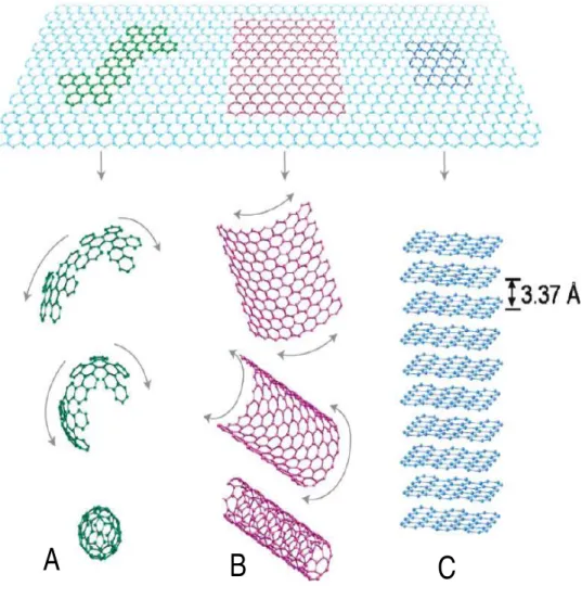
Image is adapted from reference (Feng, Xie et al. 2014). ... 19 Figure 2-7: Graphene is the building block of all graphitic forms. It can be wrapped to form (A)
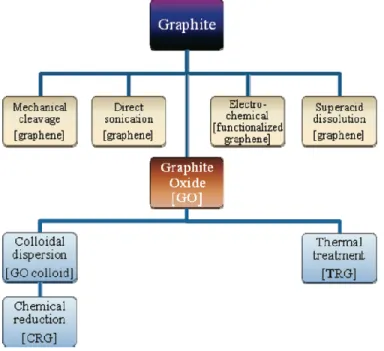
the 0-D fullerene, rolled to form (B) the 1-D nanotubes, and stacked to form (C) the 3-D graphite. The figure is reproduced from the reference (Kim, Abdala et al. 2010). ... 24 Figure 2-8: Top-down methods for production of graphene and modified graphene starting from
graphite or via graphite oxide (GO) (image is reproduced from reference (Kim, Abdala et al. 2010)). ... 25 Figure 2-9: Micromechanical exfoliation of graphene. (a and b) Adhesive tape is pressed against
graphite flakes so that the top few layers are attached to the tape (c) The tape with graphite sheets is pressed against a surface of choice. (d) by peeling off the tape, the bottom layer of
xxii graphene is left on the substrate (image is reproduced from reference (Novoselov and Neto 2012)). ... 26 Figure 2-10: Schematic illustration of conversion of graphite to graphite oxide (GO) using
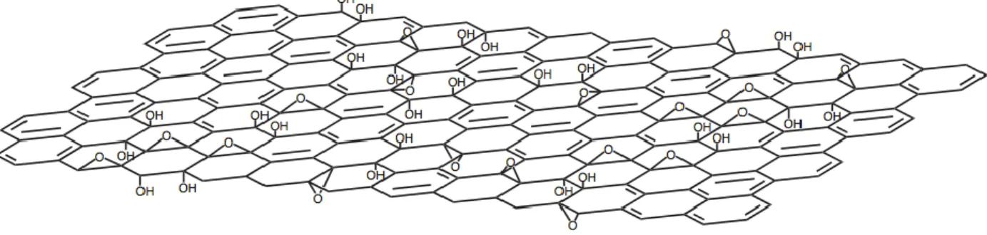
Hummer's method and reduction of GO to graphene (image is reproduced from reference (Tung, Allen et al. 2009)). ... 27 Figure 2-11: Chemical structure of graphite oxide consisting of aromatic islands seperated by
aliphatic regions containing oxygen bonded carbons as described by Lerf-Kilnowski model. This figure is reproduced from the reference (He, Klinowski et al. 1998). ... 29 Figure 2-12: (a) Electron orbitals in graphite. (b) Electron orbital of graphene: sp2 hybridized
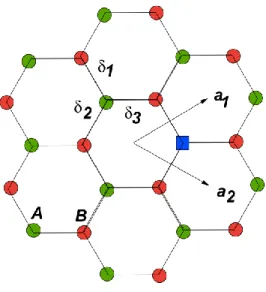
orbital responsible for the bonding on x-y plan; 2p orbital perpendicular to the x-y plan, image adapted from reference Yang . ... 31 Figure 2-13: Schematic illustration of honeycomb lattice of graphene. a1 and a2 are the lattice unit
vectors and i =1, 2, 3 are the nearest-neighbor vectors (image adapted from reference (Peres
2009)). ... 31 Figure 2-14: Blue curve illustrates the step-by-step decrease in the Hall resistivity upon adsorption
of strongly diluted NO2 and a red curve demonstrates the step-by-step increase upon its
desorption. The green curve is the control, which is exposed to pure He. (image is reproduced from reference (Schedin, Geim et al. 2007)). ... 32 Figure 2-15: Schematic illustration showing nano-indentation of graphene suspended over a hole
using AFM cantilever for determination of its mechanical properties (image is adapted from reference (Lee, Wei et al. 2008)). ... 34 Figure 2-16: Chart of Young's modulus as a function of density comparing graphene properties to
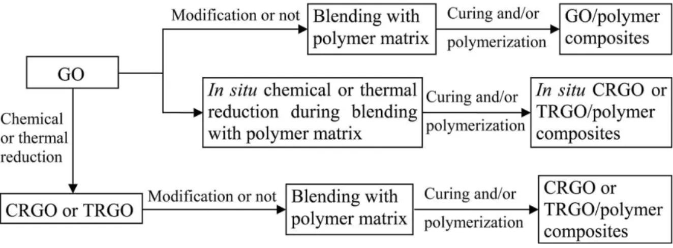
more traditional materials. Graphene density was taken as 2200 kg m-3 (image is adapted from reference (Verdejo, Bernal et al. 2011)). ... 34 Figure 2-17: The general fabrication routes for graphene-based polymer composites (GNPCs) with
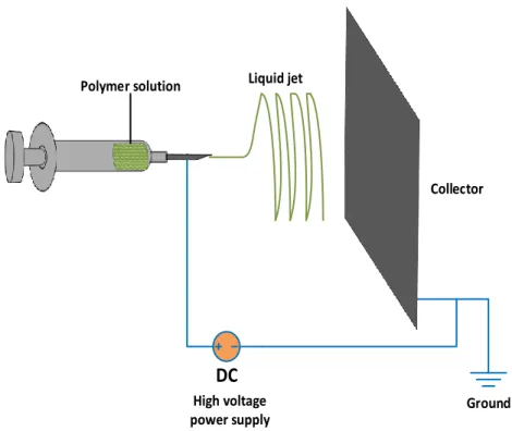
GO or RGO as fillers (image is adapted from reference (Du and Cheng 2012)). ... 38 Figure 5-1: Schematic illustration of electrospinning process ... 60
Figure 5-2: a) Chemical structures of camphor-10-sulfonic acid (HCSA), polyaniline (emeraldine salt), 1-pyrenebutanoic acid, succinimidyl ester (PBASE) and poly(ethylene oxide) (PEO) b) The dispersions of 1) GO 2) G 3) G-PBASE in 5:1 mixture of chloroform/DMF 10 days after ultrasonication c) Image of non-woven electrospun PANi/PEO/G-PBASE mat collected on an aluminium foil. ... 65 Figure 5-3: Schematic diagram for four-point probe used to measure the conductivity of
PANi/PEO/G-PBASE mats. ... 66 Figure 5-4: FTIR spectra of graphite oxide (GO), graphene (G) and PBASE functionalized
graphene (G-PBASE). ... 70 Figure 5-5: (a–c) SEM images of PANi/PEO/G-PBASE nanofibers at different magnification, (d)
distribution of diameters of the nanofibers (PANi concentration to PEO = 50 wt.%, PEO concentration to PANi = 50 wt.% and G-PBASE concentration to PANi = 5 wt.%). ... 72 Figure 5-6: (a–c) SEM images of PANi/PEO nanofibers at different magnification, (d) distribution
of diameters of the nanofibers (PANi concentration to PEO = 50 wt.%, PEO concentration to PANi = 50 wt.%). ... 73 Figure 5-7: (a–c) High-resolution TEM images of PANi/PEO/G-PBASE nanofibers at different
magnification, (a) shows an enlarged image of G-PBASE embedded in the sidewall of a PANi/PEO nanofiber (PANi concentration to PEO = 50wt.%, PEO concentration to PANi = 50wt.% and G-PBASE concentration to PANi = 5wt.%). (d) TEM image of PANi/PEO/G-PBASE nanofiber deposited on TEM copper grid with carbon support film. ... 74 Figure 5-8: (a and b) Survey X-ray photoelectron spectra of PANi/PEO and PANi/PEO/G-PABSE,
(c and d) high resolution C1s spectra of PANi/PEO and PANi/PEO/G-PABSE, (e and f) high resolution N1s spectra of PANi/PEO and PANi/PEO/G-PBASE. ... 76 Figure 5-9: (a) TGA thermographs of as spun PANi/PEO and PANi/PEO/G-PBASE and bulk G
and G-PBASE, (b) first-order derivative of TGA thermographs. ... 77 Figure 5-10: (a) I–V curves of PANi/PEO and PANi/PEO/G-PBASE nanofibers mat. (b) Electrical
xxiv Figure 6-1: Schematic representation of the fabrication of PANi/G-PBASE/PMMA nanofibers by coaxial electrospinning and subsequent shell layer removal by 1:1 (v/v) mixture of MIBK/IPA for obtaining neat PANi/G-PBASE nanofibers. ... 85 Figure 6-2: Representative SEM images of coaxial electrospun nanofibers of (a) PANi/PMMA, (b)
PANi/G-PBASE/PMMA, and (c) PANi, (d) PANi/G-PBASE after removal of PMMA shell. Histograms of fiber diameter, distribution and average fiber diameter (AFD) of (e) PANI/G-PBASE/PMMA and (f) PANi/G-PBASE fibers. ... 91 Figure 6-3: Representative TEM micrographs of electrospun (a) PANi/PMMA (b)
PANi/PMMA/G, (c) PANi and (d) PANi/G after removal of PMMA shell with 1:1 (v/v) mixture of MIBK:IPA. The inset in (d) shows the higher resolution image of graphene sheet embedded in PANi. ... 92 Figure 6-4 : FTIR spectra of core-shell structured PANi/G-PBASE/PMMA and PANi/G-PBASE. ... 94 Figure 6-5: –V curves of PANi and PANi/G-PBASE electrospun mat measured by four-point probe
from -1 V to +1 V. ... 95 Figure 7-1: Schematic illustration of fabrication of CNF/G nanofibers by single nozzle electro-
spinning using phase-separated solution of polyacrylonitrile and polyvinylpyrrolidone (PAN/PVP) in N,N-dimethylformamide (DMF) solution dispersed with various amount of PVP-stabilized graphene nanosheets (0 to 15 wt. %). ... 103 Figure 7-2: Fourier transform infrared (FTIR) spectra of G, G/PVP and PVP. The inset shows the
stabilization of G/PVP and G powders dispersed by ultrasonication in DMF after 15 days. ... 111 Figure 7-3: SEM micrographs of electrospun (a) CNF/G0, (b) CNF/G5, (c) CNF/G10, (d)
CNF/G15 (scale bar = 500nm). The number after G denotes weight percent of G relative to PAN. ... 112 Figure 7-4: : (a) Representative elemental mapping of CNF/G fiber containing 5% graphene and
(b) its corresponding EDX spectra. ... 113 Figure 7-5: Representative TEM micrographs of electrospun (a) and (b) PAN/PVP/G, (c) and (d)
Figure 7-6: Histograms of fiber diameter, distribution and average fiber diameter (AFD) of (a) PAN/PVP/G fibers (before carbonization) and (b) CNF/G (after carbonization). The number after G denotes weight percent of G relative to PAN. ... 115 Figure 7-7: Raman spectra of CNF/G15, CNF/G10 , CNF/G5 and CNF/G0 samples, respectively.
R is the intensity ratio of the D peak (1350 cm−1) to the G peak (1580 cm−1), which represents the amount of ordered graphite crystallites in the CNFs. ... 116 Figure 7-8: X-ray photoelectron survey spectrum of CNF/G0 to CNF/G15 showing C1s (∼285.9
eV), O1s (∼533.6 eV) and N1s (∼401.2 eV) peaks. ... 118 Figure 7-9: (a) Nitrogen adsorption-desorption isotherms and (b) pore size distributions determined
by DFT calculations for CNF/G nanofibers containing 0% to 15% graphene content. ... 119 Figure 7-10: (a) cyclicvoltammetry of CNF/G nanofibers at scan rate of 10 mV s−1 (b)
Galvanostatic charging/discharging curves of CNF/G samples at a specific current of 0.5 A g−1. ... 120
xxvi
LIST OF SYMBOLS AND ABBREVIATIONS
AFD Average fiber diameter
APW Average pore width
ATR Attenuated total reflectance
BET Brunauer–emmett–teller
CNF Carbon nanofiber
CNT Carbon nanotube
CRGO Chemically reduced graphene
CVD Chemical vapor deposition
DFT Density functional theory
DI water Deionized water
DMF N,n-dimethylformamide
EDX Energy-dispersive X-ray spectroscopy
G-PBASE
1-pyrenebutanoic acid, succinimidyl ester functionalized graphene
GNPC Graphene-based polymer nanocomposites
GO Graphene oxide
HCSA Camphor-10-sulfonic acid
HDPE High-density polyethylene
HOPG Highly oriented pyrolytic graphite
ICP Intrinsically conducting polymers
IPA Isopropanol / Isopropyl alcohol
LEI Lower secondary electron image
MIBK Methyl isobutyl ketone
PAN Polyacrylonitrile
PANi Polyaniline
PBASE 1-Pyrenebutanoic acid, succinimidyl ester
PC Polycarbonate
xxviii
PE Polyethylene
PEO Polyethylene oxide
PET Polyethylene terephthalate
PI Polyimide
PLA Polylactic acid
PMMA Polymethyl methacrylate
PP Polypropylene
PS Polystyrene
PTFE Polytetrafluoroethylene
PVP Polyvinylpyrrolidone
RGO Reduced graphene oxide
SEM Scanning electron microscope
TEM Transmission electron microscopy
TGA Thermogravimetric analysis
THF Tetrahydrofuran
1
CHAPTER 1
INTRODUCTION
Nanocomposites have made advancement in many industries after it was shown that most mechanical, thermal and electrical properties can be significantly enhanced by dispersing only small quantities of nanoparticles in polymer matrices. In particular, electrically conducting polymer nanocomposites have received significant attention since they exhibited sufficient conductivity for replacement of metals and inorganic materials for applications in sensors, actuators, and energy storage devices.
Electrospinning is an efficient, relatively simple and low-cost procedure to produce polymer and composite fibers with diameters ranging from several nanometers to a few micrometers. Nanofibers fabricated via electrospinning have large aspect ratios and specific surface approximately one to two orders of the magnitude larger than flat films. In this process, a charged polymeric solution ejects out of a syringe and accelerates toward a collector, mounted at a fixed distance from the needle and during this flight the polymer solution elongates and whips until it is deposited on the collector, resulting in formation of non-woven random nanofibers. The prepared non-woven electrospun mats exhibit remarkable characteristics such as high specific surface area, high porosity and interconnected porous structure. These properties make the electrospun mats a good candidate for gas or pathogen detection and energy storage applications.
A new class of polymer known as intrinsically conducting polymers (ICPs) were discovered in 1960. ICPs are intrinsically conducting in nature due to the presence of a conjugated π electron system in their structure. ICPs posse electronic properties, low ionization potentials and a high electroaffinity. This extended π-conjugated system of conducting polymer is linked to the single and double bonds in their structure. The conductivity level of ICPs can reached near to that of a
metal depending on their oxidation states and doping level. These properties have attracted many studies for application of ICPs in electronics, electrochemical, electromagnetic and sensor applications. Polyaniline (PANi) is one of the most studied ICPs and it is unique due to its ease of synthesis, environmental stability, and simple doping/dedoping chemistry, yet it is relatively hard to process compared to most other polymers. As is common among ICPs, it has a fairly rigid backbone due to its high aromaticity. Thus, the elasticity of its solutions is generally insufficient for it to be electrospun directly into fibers. Moreover, PANi has poor solubility in common organic solvents, which further complicates it electrospinability. However, if aforementioned processing limitations of PANi can be addressed to obtain conductive fiber mats, it can be used for a variety of applications such as chemoresistive sensors. In this thesis, two strategies were followed to electrospun PANi for the mentioned application:
1) By blending doped-PANi with insulating polymers, which are easily electrospinnable. However, the presence of an insulator polymer will decrease the fibers conductivity due to reduction of the conducting component in the blend. A good strategy to compensate for the addition of insulating polymer and to improve the overall electrical properties of the electrospun fibers blend is to incorporate carbon-based conductive nanofillers into the fibers and in this work graphene was selected.
2) By utilizing coaxial electrospinning technique to produce core-shell structured nanofiber with PANi at the core segment and an easily electrospinnable polymer at shell segment. Subsequently, the shell segment is removed by solvent etching to produce pure PANi nanofibers.
Since the discovery of graphene in 2004, it has attracted tremendous research interest. Graphene is a single-atom-thick, two-dimensional sheet of sp2-hybrized carbon atoms arranged in a honeycomb crystal structure with outstanding properties such as extraordinary physical properties (high values
3 of its Young’s modulus (∼1,100 GPa), fracture strength (125 GPa), high thermal conductivity
∼5,000 W m−1
K−1), excellent mobility of charge carriers (200,000 cm2 V−1 s−1), and high specific surface area (calculated value, 2,630 m2 g−1). Therefore, considering the excellent properties of graphene, a highly conductive PANi composite with graphene as nanofillers can be obtained. In the second part of this thesis, fabrication of polyacrylonitrile (PAN) based carbon nanofibers (CNFs) embedded with graphene nanosheets for supercapacitor applications is investigated. In recent years, there has been an extensive research on the fabrication of PAN based carbon CNFs as a great candidate for electrode material of energy storage devices mainly due to CNFs high surface area and chemical resistance. However, the low conductivity of CNFs has limited their power densities and hindered their potential usage in application where high power densities are sought after, such as in supercapacitors. Graphene nanosheets have demonstrated attractive properties as a new family of carbon nanomaterials for use in electrochemical energy generation and storage application. Thus, given the high surface area and electrical conductivity of graphene, an essential characteristics of an electrode material for energy production and storage, it is an attractive material for applications in energy storage systems and provides the possibility of improving the power density of CNFs by embedding graphene nanosheets into the precursor polymer matrix.
This dissertation is based on three articles that have been published or submitted to scientific journals and is comprised of the following sections:
Chapter 2 provides a literature review on the related topics investigated in this dissertation and followed by Chapter 3, which discusses the originality and main objectives of this dissertation.
The summary and organization of the articles are described in Chapter 4. Chapter 5 and Chapter 6 present result for the first part of this thesis where fabrication PANi nanofibers embedded with graphene by blending and coaxial electrospinning method is studied. Chapter 7 presents results of second part of this thesis where graphene filled CNFs for supercapacitor applications is studied. Chapter 8 provides a general discussion on the results obtained in this thesis followed by Chapter 9 where conclusions and recommendations for this work is presented.
5
CHAPTER 2
LITERATURE REVIEW
This chapter provides a comprehensive literature review covering many aspects of graphene-based polymer nanofiber fabrication which forms the backbone of this research. In Section 2.1, an overview of single nozzle electrospinning and coaxial electrospinning is provided. Section 2.2 focuses on intrinsically conductive polymers and particularly polyaniline. Section 2.3 focuses on carbon nanofibers, their preparation via electrospinning and applications in supercapacitors. Section 2.4 deals with overview of graphene, its fabrication followed by highlight of its properties.
2.1 Electrospinning
2.1.1 Single-nozzle electrospinning
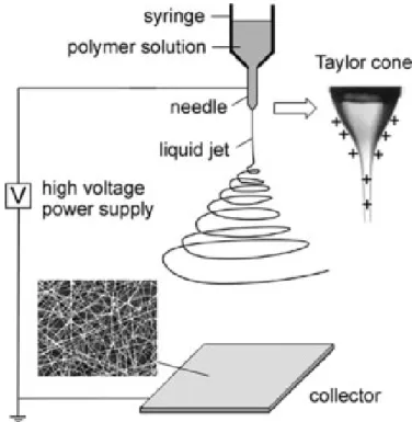
Electrospinning is an efficient, relatively simple and low-cost procedure to produce polymer and composite fibers with diameters ranging from several nanometers to a few micrometers (Doshi and Reneker 1995, Reneker and Chun 1996). The main advantages of the electrospinning process are its technical simplicity and its easy adaptability. Nanofibers fabricated via electrospinning have large aspect rations and specific surface approximately one to two orders of the magnitude larger than flat films, making them excellent candidates for potential applications in sensors (Prasad, Das et al. 2009). There are basically three components to fulfill the process: a high voltage supplier, a micro-syringe with a needle of small diameter, and a collecting screen. The schematic of this process is illustrated in Figure 2-1. The collector can be made of any shape according to product requirements such as flat plate, rotating drum, or patterned collector. In most cases, the collector is simply grounded, as shown in Figure 2-1.
The electric field is applied to the end of the micro-syringe that contains the solution fluid held by its surface tension. This induces a charge on the surface of the liquid. Mutual charge repulsion and the contraction of the surface charges to the counter electrode cause a force directly opposite to the surface tension (Fang and Reneker 1997). As the intensity of the electric field is increased, the hemispherical surface of the fluid at the tip of the micro-syringe needle elongates to form a conical shape known as the Taylor cone. By further increasing the electric field, a critical value is attained with which the repulsive electrostatic force overcomes the surface tension and charged jet of the fluid is ejected from the tip of the micro-syringe.
Figure 2-1: Schematic illustration of the fabrication of polymer nanofiber composite by electrospinning. The insets show a hemispherical surface of the fluid at the tip of the micro-syringe needle known as the Taylor cone (image is reproduced from reference (Li and Xia 2004)).
The discharged polymer solution undergoes an instability and elongation process, which allows the jet to become very long and thin. Meanwhile, the solvent evaporates, leaving behind a charged
2. Electrospinning: Setups and M echanisms
2.1. The Basic Setup for Electrospinning
Figure 2 shows a schematic illustration of the basic setup for electrospinning. I t consists of three major components: a high-voltage power supply, a spinneret (a metallic needle),
and a collector (a grounded conductor). D irect current (D C) power supplies are usually used for electrospinning although the use of alternating current (A C) potentials is also feasi-ble.[3,9] The spinneret is connected to a syringe in which the polymer solution (or melt) is hosted. With the use of a syringe pump, the solution can be fed through the spinneret at a con-stant and controllable rate. When a high voltage (usually in the range of 1 to 30 kV ) is applied, the pendent drop of poly-mer solution at the nozzle of the spinneret will become highly electrified and the induced charges are evenly distributed over the surface. A s a result, the drop will experience two major types of electrostatic forces: the electrostatic repulsion between the surface charges; and the Coulombic force exerted by the external electric field. U nder the action of these elec-trostatic interactions, the liquid drop will be distorted into a conical object commonly known as the Taylor cone (see the inset of Fig. 2).[3,4] Once the strength of electric field has sur-passed a threshold value, the electrostatic forces can over-come the surface tension of the polymer solution and thus force the ejection of a liquid jet from the nozzle. This electri-fied jet then undergoes a stretching and whipping process, leading to the formation of a long and thin thread. A s the liquid jet is continuously elongated and the solvent is evapo-rated, its diameter can be greatly reduced from hundreds of micrometers to as small as tens of nanometers. A ttracted by the grounded collector placed under the spinneret, the charged fiber is often deposited as a randomly oriented,
non-woven mat, see the inset of Figure 2 for the scanning electron microscope (SEM ) image of a typical sample. With the use of this relatively simple and straightforward technique, more than 50 different types of organic polymers have already been processed as fibers with diameters ranging from tens of nano-meters to a few micronano-meters.[3]
2.2. H ow Electrospinning Works
A lthough the setup for electrospinning is extremely simple, the spinning mechanism is rather complicated. A s in electro-spray, electrospinning also involves complex electro±fluid± mechanical issues. Before 1999, the formation of ultrathin fibers by electrospinning was often ascribed to the splitting or splaying of the electrified jet as a result of repulsion between surface charges.[3a] Recent experimental observations demon-strate that the thinning of a jet during electrospinning is mainly caused by the bending instability associated with the electrified jet.[4,10] Figure 3A shows the photograph of a spin-ning jet.[10b] I t is obvious that the jet was initially a straight line and then became unstable. I t appears that the
cone-shaped, instability region is composed of multiple jets. H ow-ever, a closer examination using high-speed photography (Fig. 3B) establishes that the conical envelope contains only a single, rapidly bending or whipping thread. I n some cases, splaying of the electrified jet might also be observed, though it was never a dominant process during spinning.[10] The fre-quency of whipping is so high that conventional photography cannot properly resolve it, giving the impression that the orig-inal liquid jet splits into multiple branches as it moves toward the collector.
Based on experimental observations and electrohydrody-namic theories, mathematical models have been developed by several groups to investigate the electrospinning process.
R
E
V
IE
W
D. Li, Y. Xia/ Electrospinning of Nanofibers
Adv. Mater. 2004, 16, No. 14, July 19 http:/ / www.advmat.de 2004 WILEY-VCH Verlag GmbH & Co. KGaA, Weinheim 1153 Figure 2. Schematic illustration of the basic setup for electrospinning.
The insets show a drawing of the electrified Taylor cone and a typical SEM image of the nonwoven mat of poly(vinyl pyrrolidone) (PVP) nanofi-bers deposited on the collector.
Figure 3. Photographs illustrating the instability region of a liquid jet electrospun from an aqueous solution of poly(ethylene oxide) (PEO). The capture time was on two different scales: A) 1/ 250 s, and B) 18 ns, respectively. Note that the path of the jet shown in B has been traced to improve the visibility. These two figures were adapted from [10b] with permission. Copyright Elsevier Science, 2001.
7 polymer fiber. In the case of the melt, the discharged jet solidifies when it travels in the air (Huang, Zhang et al. 2003).
2.1.1.1 Control of Fiber Morphology and Diameter
As studies on the electrospinning process have been conducted, there have been some efforts to characterize the structure and morphology of nanofibers as a function of polymer solution and process parameters. Many parameters can influence the electrospinning of nanofibers. These parameters include: i) the intrinsic properties of the solution such as viscosity, elasticity, conductivity, and surface tension. ii) the operational conditions such as electric potential at the needle, the feeding rate for the polymer solution, and the distance between the syringe and the collector screen (Reneker and Chun 1996). iii) ambient parameters such as temperature, humidity and air velocity (Doshi and Reneker 1995). Two of the important factors that affect the viscosity of the solution are the molecular weight of the polymer and the solution concentration. Generally, when a polymer of higher molecular weight is dissolved in a solvent, its viscosity will be higher than solution of the same polymer but of a low molecular weight. One of the conditions necessary for electrospinning to occur where fibers are formed is that the solution consists of polymer of sufficient molecular weight and the solution must be of sufficient viscosity. As the jet leaves the needle tip during electrospinning, the polymer solution is stretched as it travels towards the collection plate. During the stretching of the polymer solution, it is the entanglement of the molecule chains that prevents the electrically driven jet from breaking up thus maintaining a continuous solution jet. The molecular weight of the polymer represents the length of the polymer chain, which in turn have an effect on the viscosity of the solution since the polymer length will determine the amount of entanglement of the polymer chains in solvent. Another way to increase
the viscosity of the solution is to increase the polymer concentration. Similar to increasing the molecular weight, an increased in the concentration will result in greater polymer chain entanglements within the solution which is necessary to maintain the continuity of the jet during electrospinning. Fibers measuring less than 1 µm in diameter were first spun by electrostatic means from N,N-dimethylformamide (DMF) solutions of acrylic resin (Baumgarten 1971) and this study highlighted the effects of solution viscosity on the fiber diameter and jet length. The experiment showed that the fiber diameter increased with the solution viscosity. The relationship between the fiber diameter and solution viscosity was established by Baumgart and can be expressed by the Equation 2-1, where d is fiber diameter and is solution viscosity in poise.
𝑑 = 𝜂0.5 2-1
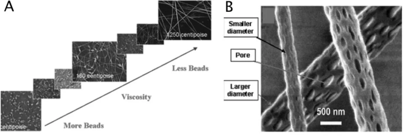
One challenge in electrospinning is the occurrence of defects such as beads in polymer nanofibers. As shown in Figure 2-2 (A) (Jaeger, Schönherr et al. 1996), The formation of beads can be attributed to three forces: i) surface tension tends to convert the liquid jet into one or many spherical droplets (Rayleigh instability) ii) the electrostatic repulsion between charges on the jet surface tends to increase the surface area and favors the formation of a thin jet rather than beads. iii) Viscoelastic force also resists rapid changes in shape and supports the formation of fibers with smooth surfaces (Li and Xia 2004). Fong et al. have shown that polymer concentration also affects the formation of the beads in nanofibers and in general the higher the polymer concentration, the lower number of beads will form (Fong and Reneker 1999). The authors showed that as the viscosity increased for PEO/water solutions, the fiber diameter increased and the shape of beads changed from spherical to spindle-shaped and gradually disappeared, as shown in Figure 2-2.
9 Reneker et al. have reported that the nanofibers beads can be minimized by reducing the surface-tension of the polymer solution (Doshi and Reneker 1995).
Figure 2-2: A) SEM photographs of electrospun nanofibers from different polymer concentration solutions (image is reproduced from reference (Fong and Reneker 1999)). B) nanofibers with different diameters and pores (image is reproduced from reference (Bognitzki, Czado et al. 2001).
Researchers showed the influence of solution properties on electrospun fiber diameter and morphology. Studies with poly(styrene), poly(urethane), poly(lactide), poly(vinyl chloride), and poly(vinylpyrrolidone) have yielded similar trends in fiber morphology with polymer concentration or solution viscosity. In general, as the polymer concentration increases, and subsequently the entanglement density in solution increases, the fiber morphology gradually changes from droplets to beaded fibers to uniform fibers. Thus, for electrospinning to occur a minimum solution concentration must be attained, and below this concentration, the Rayleigh instability domains and electrospraying occurs. To quantify the effect of entanglements on electrospun fiber formation process, the Berry number (Be), a dimensionless parameter, is used. In this equation, η is the intrinsic viscosity and C is the polymer concentration (Chen, Berry et al.).
𝐵𝑒 = [𝜂]𝐶 2-2
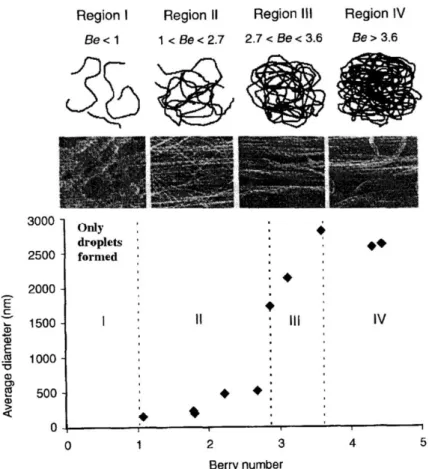
In very diluted solutions, when the Be is less than unity, the molecules of the polymer are sparsely distributed in the solution. There is a low probability of individual molecules being entangled to each other. At a Be of greater than unity and as the concentration of the polymers increases, the level of molecular entanglement increases, resulting in more favorable conditions for the formation of fibers. Frank et al. electrospun poly(lactide)/chloroform solutions and have evaluated systematically the effects of polymer concentration and Be, on the average fiber diameter (AFD) and fiber morphology, shown in Figure 2-3 (Tao and Institute 2005).
Region I, where Be <1, is characterized by a very diluted polymer solution with molecular chains that barely touch each other. This makes it almost impossible to form fibers by electrospinning of such a solution, since the chains are not entangled enough to form a continuous fiber and the effect of surface tension will make the extended conformation of a single molecule unstable. As a result, only polymer droplets are formed. In region II, where 1<Be <3, AFD increases slowly with Be from ~ 100 nm to ~ 500 nm. In this region, the degree of molecular entanglement is just sufficient for fibers to form. The coiled macromolecules of dissolved polymer are transformed by the elongational flow of the polymer jet into oriented molecular assemblies with some level of inter and intra-molecular entanglement. These entangled networks persist as fiber solidifies. In this region, some bead formations are observed as a result of the relaxation of the polymers and the effect of surface tension. In region III, where 3< Be <4, AFD increases rapidly with Be, from ~ 1700 nm to ~ 2800 nm. In this region the entanglement of the molecular chain becomes more intensive, contributing to an increase in the viscosity of the polymer. Because of the intense level of molecular entanglement, a stronger electric field is needed for fibers to form by electrospinning.
11 In region IV, where Be >4, the AFD is less dependent on Be. With a high degree of inter and intra-molecular chain entanglement, other processing parameters such as the strength of the electric field and spinning distance become dominant factors that affect the diameter of the fiber.
Figure 2-3: Fiber diameter and morphology as a function of Berry number (Be) (image is reproduced from reference (Ko 2006)).
Another significant factor in nanofiber's diameter, is the applied electrical voltage and as the voltage gets higher more fluid ejects from the needle resulting in a larger fiber diameter (Demczyk, Wang et al. 2002). Moreover, a higher feeding rate for the solution always leads to the formation of thicker fibers (Li and Xia 2004).
Generally, the electrospun fibers are deposited on a fixed collector as randomly oriented, three-dimensional non-woven membrane structure with a wide range of fiber diameter distribution. However, for many applications it is necessary to control the spatial orientation of the nanostructures. It was shown that be using a cylinder with high rotating speed collector, it is possible to fabricate aligned electrospun nanofibers and the collected fibers were oriented parallel to each other (Theron, Zussman et al. 2001).
2.1.2 Coaxial Electrospinning
Coaxial electrospinning is a branch of electrospinning which was developed in order to address the need for electrospinning of materials that was not previously electrospinnable using the single nozzle electrospinning technique and to develop nanofibers that posses a core-shell structure (Qu, Wei et al. 2013). Sun et al. first demonstrated the use of coaxial electrospinning setup in 2003 by using the same polymer, poly(ethyleneoxide) (PEO) for both core and shell segment of the nanofibers. They also electrospun unspinnable polymer, such as poly(dodecylthiophene) (PDT) and palladium(II) acetate (Pd(OAc)2), in the core segment of fibers by using easily electrospinnable
polymers, such as PEO and poly(L-lactide) (PLA) as a guide for the shell segment.
The general set up adopted by most researchers is quite similar to that used for single nozzle electrospinning (Elahi, Lu et al. 2013). In coaxial electrospinning, a smaller (inner) capillary is fitted concentrically inside the bigger (outer) capillary to make the coaxial spinneret and two syringes will feed the core and shell solutions to the spinneret. As the two solutions meet at the tip of the needle they form a compound Taylor cone with a core-shell structure when under the electric
13 field. The stress generated in the shell solution causes shearing of the core solution by viscous dragging and contact friction which deforms the core solution into the conical shape with the shell solution and forms the compound Taylor cone at the tip of the needle (Li and Xia 2004). The schematic of this process is shown in Figure 2-4. As the electrostatic force is applied on the compound Taylor cone, the shell solution elongates and stretches and once the charge accumulation reaches the threshold value, due to the increased applied potential, the jet is ejected towards the collector. The core-shell structure is kept intact as the jet is drawn by electrostatic force and flies towards the collector resulting in formation of nanofibers with core-shell structure at the collector.
Figure 2-4: The configuration of coaxial electrospinning setup showing the formation of compound Taylor cone at the tip of the needle [(Li, Zhao et al. 2010)].
Coaxial electrospinning processing parameters are similar to those discussed earlier for single nozzle electrospinning. However, the introduction of second phase complicates to electrospinning process as miscibility and stress due to viscosity differences of the two solutions and difference between conductivity of two phases can play an important role in formation of fibers (Qu, Wei et al. 2013). Some of the important parameters in the coaxial electrospinning is discussed in the next sections.
2.1.2.1 Solution concentration
The polymer concentration is vital to electrospinability of a solution and the concentration should be high enough for entanglements to occur. For coaxial electrospinning the increase in solution concentration causes an increase in fiber diameter, the same relationship which is valid for single nozzle electrospinning. Zhang et al. increased the core-solution concentration while keeping the shell-solution concentration constant (Zhang, Huang et al. 2004). They observed an increase in core diameter as the concentration of core solution was increased. Also as expected, as the core diameter increased the shell diameter decreased and overall fiber diameter increased.
2.1.2.2 Solution viscosities
The key driver for formation of core-shell structured fibers in coaxial electrospinning is the shell solution. The shell solution viscosity should be high enough that can exert sufficient viscous stress on the core solution and overcome the interfacial tension between the two solutions and result in formation of compound Taylor cone (Díaz, Barrero et al. 2006).
2.1.2.3 Immiscibility of core-shell solutions
The selection of solvents and polymers in shell and core solutions are key in formation of compound Taylor cone and successful coaxial electrospinning. In a coaxial system, it is important
15 that the solvent in each of solutions do not precipitate the polymer in other phase as they meet at the tip of the needle (Yu, Fridrikh et al. 2004) and the interfacial tension between the two phases be as low as possible to yield an stable compound Taylor cone (Díaz, Barrero et al. 2006). It is also reported that when two miscible solutions are used, coaxial electrospinning can be also successful and the core-shell structured fibers can still be obtained (Sun, Zussman et al. 2003, Yu, Fridrikh et al. 2004). Although, certain degree of diffusion between core and shell layers can occur and it will be challenging to maintain the stable coaxial electrospinning process due to precipitation problem that can occur when two solutions at the tip of the needle (Li and Xia 2004).
2.1.2.4 Solvent vapor pressure:
The morphology of fibers can be strongly affected by the types of solvents used in the core and shell solutions. It is reported that usage of high vapour pressure solvents such as chloroform or acetone for core solution creates a thin layer at the interface of core and shell layers due to fast evaporation rate of the solvent which will cause the core segment to ultimately collapses. This phenomenon is due to creation of vacuum because the thin layer traps the solvent and when the solvent fully leaves the structure, the structure collapses and ribbon-like structures are created (Li, Babel et al. 2004). Therefore, high vapour pressure solvents should not be used as they can also disrupt the formation of compound Taylor cone (Larsen, Spretz et al. 2004).
2.1.2.5 Solution conductivity
Another important factor in the formation of fibers in coaxial electrospinning is the the conductivity of the solution. Solutions with high conductivity usually lead to fibers with smaller diameter since these solutions have higher surface charge density which cause an increase in the elongational force on the jet due to self-repulsion of the excess charges under a given electrical field (Hohman, Shin et al. 2001). In coaxial electrospinning the difference between conductivities of shell and core
solution can affect the fiber formation. Yu et al. shown that the more conductive core solutions are pulled at the higher rate by electrical field and therefore causes a discontinuity in the core-shell structure (Yu, Fridrikh et al. 2004). On the other hand, higher shell conductivity would result in higher shear stress on the core layer and will cause formation of a thinner core layer (Li and Xia 2004). Therefore, it is possible to embed solutions with low conductivity inside of a high conductivity shell layer (Elahi, Lu et al. 2013).
2.2 Intrinsically conductive polymers (ICPs)
Conducting polymers are a unique class of materials which structurally resemble organic insulating polymers but are actually semiconductors or conductors. Most conducting polymers such as polyacetylene, polypyrrole, polyaniline and polythiophene require a change in oxidation state to be converted into their conducting forms. Polyacetylene, possibly the most conducting of these polymers, has conductivities reported above 105 S/cm, however, it degrades upon exposure to air. Polythiophene and polypyrrole are difficult to process even with very polar organic solvents due to strong inter-chain attractions.
2.2.1 Polyaniline (PANi)
Polyaniline (PANi) has been of significant interest due to its low cost, stability, increased processability, relative to other conduction polymers (Stenger-Smith 1998). The fact that it can be synthesized to obtain thin or thick films, nanoparticles, composites and even can be drawn into nanofibers of diameters of a few nanometers gives it a distinct edge over a lot of other materials. The monomer aniline was first synthesized in 1862 (Letheby 1862). The polymeric oxidation products of aniline were commonly refereed to as ``aniline black'' and were widely used in the
17 textile industries for dyeing and also heat resistant in paints (Stenger-Smith 1998). The base structure of polyaniline, as shown in Figure 2-5, consists of a reduced unit or benzenoid attached to an amine (-NH-), and an oxidized unit or quinoid attached to an imine (-N=). The amines and imines are the nitrogenous centers of polyaniline which may react with dopant agents and/or analyte and the ratio of amines to imines dictates the oxidation state. Polyaniline exists in several oxidized forms. The most studied and widely accepted are the leucoemeraldine which is the fully reduced form, y = 1 in Figure 2-5, the emeraldine form which is half oxidized, half reduced, y = 0.5, and the pernigraniline form which is the fully oxidized form, y = 0 (Haynes 2008).
Figure 2-5: Base structure of polyaniline for y=1 the oxidation state is leucoemeraldine, for y=0 the polymer is in the pernigraniline oxidation state and for y=0.5 the polymer is in the emeraldine oxidation state (image is reproduced from reference (Haynes 2008).
Polyaniline has been known for 150 years, however it was after the discovery of its conducting properties that research area in this area has increased tremendously. Polyaniline is environmentally stable, easy to synthesize and can be reversibly transformed from conduction to insulation from using acid-base reactions (Syed and Dinesan 1991). It has advantages over other conducting polymers in that it can be transformed from one oxidation state to another by simply oxidation/reduction chemistry. Thus, polyaniline has found increasing applications in the area of sensors, field effect transistors, rechargeable batteries, capacitors, electronic devices, etc. (Skotheim, Elsenbaumer et al. 1998, Wessling 1998). All the three oxidation states of polyaniline mentioned above exist in two forms, salt form (doped state) and base from (undoped state) and of
these oxidation states only the emeraldine salt form is conductor and the rest are insulators (Kolla, Surwade et al. 2005).
2.3 Carbon nanofibers
2.3.1 Introduction
Energy is one of the top global issues facing the world for the next 50 years and nanotechnology is providing a platform to solve this challenge by fabricating nanofibers optimized for energy storage applications. Supercapacitors (Zhang and Zhao 2009) and lithium ion batteries (LIBs) (Bruce, Scrosati et al. 2008) are at the frontier of this efforts, and currently they are powering numerous portable consumer electronic devices from wearable smart-devices to laptops. In 1879, Thomas Edison prepared first carbon fiber (CF) by carbonization of cotton and bamboo which was subsequently used as the filament of a light bulb. CFs has developed tremendously scientific research and applications (Lu, Zu et al. 2012). Carbon nanofibers (CNFs) have been applied as promising materials in many fields but mainly as energy conversion and storage (Wangxi, Jie et al. 2003, Feng, Xie et al. 2014). There are some differences between CFs and CNFs. First, CFs have diameters in the range of several micrometers, whereas, CNFs have diameters of 50-200 nm. Second, as Figure 2-6 illustrates the structure of CF and CNF is different (Feng, Xie et al. 2014). The CNFs can be mainly fabricated by catalytic vapor deposition growth (Tibbetts, Lake et al. 2007) (Rodriguez 1993) and electrospinning. CNFs are normally produced from three polymeric precursors: polyacrylonitrile (PAN), cellulose, and pitch (Zhang, Aboagye et al. 2014).