1 INTRODUCTION
In the field of civil engineering, repair and rehabili-tation have drawn significant attention in the recent years. Even though engineers have been repairing deteriorated structure for many years now, the rate of unsuccessful concrete repairs remains unaccepta-bly high. Because of the lack of knowledge gained on the influence of certain fundamental parameters, the achievement of durable repairs is reduced in some circumstances to merely a “hit or miss” proce-dure.
The aim of concrete repairs is to prolong the useful service life of an existing structure, to restore its load-carrying capacity and stiffness, and/or to strengthen its members. A prerequisite to achieve adequate composite action is lasting bond between the existing substrate and the new-cast material. In this respect, concrete surface preparation prior to re-pair material application is of critical importance. In fact, regardless of the repair material and application method employed, the quality of the surface prepara-tion prior to repair will often determine whether a repair project is a success or a failure, and whether or not a repaired structure is durable.
Adhesion of a concrete repair to an existing sub-strate is a complex phenomenon that involves differ-ent types of bond: chemical bond (chemical reaction
between the substrate and the repair material),
me-chanical bond (associated with the interpenetration
of the repair material into the roughness and porosity of the substrate, resulting in mechanical anchorage) and physical bond (related to the van der Waals and surface tension forces (Courard 1999)). Each of the-se components has been studied in a number of in-vestigations over the past 30 years, which led to sig-nificant progress in the overall understanding of the question. However, many aspects remain obscure to this day, for instance their relative importance upon bond strength development.
As part of a wider research program intended to lead to the development of performance criteria for sur-face preparation of concrete prior to repair, the ex-perimental work reported herein focuses on the most influential parameters upon bond strength develop-ment. The general objective is to provide the indus-try with guidelines to achieve systematically strong and durable repair bond, including performance cri-teria and guide specifications for surface prepara-tion. The specific objectives were:
• to evaluate existing methods for assessment of the roughness parameters of a prepared surface; • to establish correlation between pull-off tensile
strength, shear bond strength, and surface rough-ness;
Concrete repair bond: evaluation and factors of influence
B. Bissonnette
CRIB, Civil Engineering Department, Laval University, Quebec City, QC, Canada
L. Courard
GeMMe Building Materials, ArGEnCo Department, University of Liège, Liège, Belgium
A. Garbacz
Warsaw University of Technology, Warsaw, Poland
A.M. Vaysburd
Vaycon Consulting, Baltimore, MD, U.S.A.
K.F. von Fay
US Bureau of Reclamation, Denver, CO, U.S.A.
ABSTRACT: Repair and strengthening of existing concrete structures are among the biggest challenges civil engineers are facing today and will have to face in the years to come. Present concerns of sustainable development emphasizing repair instead of new construction will only strengthen this trend. Concerted efforts towards improving the durability of concrete repairs are still needed from scientists and engineers. One of the critical aspects of durability of concrete repairs and overlays is lasting and sufficient interfacial bond between repair material and existing concrete substrate. This paper summarizes some of the findings of a collaborative study devoted to the most significant factors influencing bond in repairs (roughness, degree of saturation and carbonation of the substrate) and its field evaluation (type of loading, device misalignment). Based on the test results collected in different test programs, guideline-type recommendations for surface preparation prior to repair were issued.
• to evaluate effect of load misalignment upon ten-sile pull-off test results;
• to evaluate the optimum moisture conditioning of a concrete substrate prior to repair; and
• to evaluate the effect of substrate carbonation up-on bup-ond strength.
2 METHODOLOGY
2.1 Bond strength evaluation
In different test series conducted to evaluate the ef-fect of selected parameters upon repair bond, re-paired test slabs were characterized exhaustively for bond strength using pull-off tests and, in some cases, torsional bond tests.
For the evaluation of tensile bond strength, the most widely used method is the pull-off test (e.g. ASTM C1583). This test method consists of drilling a core through the repair material, down into the substrate, gluing a steel dolly onto the top of the core with epoxy, and using a special device to pull on the steel dolly. The tensile bond strength is equal to the max-imum recorded stress when failure occurs in the in-terfacial zone, whereas a lower boundary value of bond strength is obtained when failure occurs else-where.
Under service conditions, the repair interface is in fact subjected to both tensile and shear stresses. To this day, very little data in relation with shear bond strength have been reported. Torsional shear tests have thus been carried out in this study to evaluate the bond shear response and sensitivity with respect to the tensile behavior. In this test procedure, a ring glued to the surface is twisted off using a torque housing with eccentric loading. The housing is an-chored to the surface and the loading is performed with the same pulling unit as in the pull-off test pro-cedure (different adapters).
2.2 Influence of load misalignment
In addition to the type of loading (tension vs. tor-sion), the influence of load misalignment upon pull-off test results was also investigated. Series of six 600×400×100-mm concrete slabs were manufac-tured for each of three concrete mixtures (30-MPa, 40-MPa, 50-MPa). After 28 days of moist curing, the concrete slabs were prepared by sandblasting and the tensile pull-off experiments were conducted us-ing core depths of 15 and 30 mm and corus-ing axis in-clinations of 0°, 2°, and 4°. A theoretical FEM anal-ysis taking into account the same variables and parameters was performed in parallel.
2.3 Influence of surface preparation: roughness
and mechanical integrity
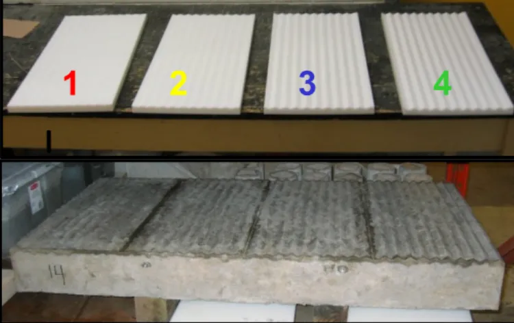
In order to cover a sufficiently large spectrum in terms of roughness and, at the same time, assess the most usual surface preparation techniques, the fol-lowing methods were selected for investigation: sandblasting (SaB), shotblasting (ShB), scarifying (Sc), 100-MPa handheld hydro-jetting (HJ), and 7-kg jack hammering (JH). In addition, to avoid the presence of induced damage and isolate the effect of roughness upon bond strength, an artificially pro-filed test slab was cast. V-shape rippled acrylic dies were installed at the bottom of the slab form to ob-tain wave amplitude values of 2, 4, 6 and 8 mm re-spectively in four adjacent areas along the specimen length, the wavelength being of 30 mm in all of them (see Fig. 1). It should be mentioned that for this artificially profiled slab, tensile bond was de-termined on cores tested in direct tension.
As part of the test program reported herein, two se-ries of 625×1250×150-mm concrete slabs (25-MPa and 35-MPa concrete mixtures) were manufactured. The test slabs were exposed to drying until relative dimensional stability was achieved, after what sur-face preparation was performed. The artificially-profiled slabs (one per slab series) were very lightly sandblasted to remove laitance.
Figure 1. V-shape rippled acrylic dies and resulting profiled slab.
After surface preparation, evaluation of surface in-tegrity and characterization of surface roughness were performed.
Surface roughness of the concrete substrates was evaluated using Moiré-type optical profilometry. The method has the advantage of capturing all the required information at once and storing it into a digital format, allowing a precise and quite exhaus-tive characterization of the surface profile. The pa-rameter used here to describe surface roughness quantitatively is the average half-amplitude (Ra) of
the profile. Complementarily, the resulting slab sur-face profiles were also appraised in accordance with the Concrete Surface Preparation index (CSP)
posed by the International Concrete Repair Institute (ICRI).
Surface integrity of the prepared test slabs was eval-uated through pull-off experiments and Schmidt
hammer soundings. Seeking a simple and
field-friendly way to assess surface integrity prior to re-pair, Schmidt hammer soundings were performed in a systematic fashion on all prepared slabs, using a template grid with regularly-spaced data points col-lected in the X- and Y- directions over the whole surface. Pull-off tests were performed immediately after the Schmidt soundings, in accordance with the procedure proposed by Courard and Bissonnette (2004).
2.3 Evaluation of the substrate moisture content In this part of the test program, two concrete surface moisture test procedures were investigated, namely the Initial Surface Absorption test (ISAT) [35] and a modified version of the Capillary Suction test (MCST) [36]. The objective was to correlate the moisture condition of the concrete surface to the wa-ter penetration characwa-teristics evaluated through the-se tests.
A series of test specimens was made with three ordi-nary Portland cement concrete mixtures (30-MPa, 40-MPa, 50-MPa). Three different surface treat-ments were performed (no treatment, sandblasting and waterjetting) before the specimens were stored in eight different moisture conditions to cover the range from 30 to 100 % relative humidity (RH). Af-ter moisture conditioning assessment, the slabs were then repaired (75-mm overlay) with a 45-MPa repair concrete. The repaired specimens were moist-cured for 7 days, after what they were air-dried until bond strength tests were carried out.
2.4 Evaluation of the effect of carbonation on bond In this part of the project, a series of eighteen 400×400×100-mm slabs were cast with a 28-MPa concrete mixture. For half of those slabs, the surface was prepared superficially for repair by sandblast-ing, while for the other half, chipping hammer was used. In each group, four slabs were protected from carbonation (control), and five slabs underwent con-trolled carbonation in a laboratory carbonation chamber. The control slabs were protected with plas-tic sheet and duct tape to avoid carbonation. Slabs were undergoing carbonization for 75 days and reached a carbonation depth of greater than 3 mm. The carbonated surface of the test slabs was then overlaid with 100 mm thick, 28-MPa concrete. A
to-tal of nine pull-off bond tests were performed on each overlayed slab.
3 RESULTS AND ANALYSIS
3.1 Influence of surface preparation (roughness and
mechanical integrity of the substrate)
3.1.1 Roughness of the susbtrate
The surface roughness half-amplitude values (Ra)
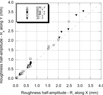
corresponding to the various surface preparation profiles, as obtained by optical profilometry, are plotted on the graph of Figure 2. The values record-ed for the ICRI CSP rubber templates are also dis-played on this graph. The largest half-amplitude val-ues (1.50 – 3.75 mm) were obtained with the jack hammer and hydrojetting, while the lowest values were recorded respectively for the scarified, the shotblasted and the sandblasted surfaces (< 1.00 mm). It can also be observed that for all slabs and templates, surface roughness is uniform, with most data points sitting on or close to the equality line. As shown on the graph of Figure 2, the ICRI CSP plates merely cover the roughness values recorded for scarifying, all other techniques being out of range for the experimental conditions. As convenient a tool these templates can be, with the existing scale, their use is confined to surface treatment applica-tions where very little material is actually removed.
Figure 2. Results of roughness evaluation performed after sur-face preparation by optical profilometry on both 25- and 35-MPa substrates. (here and elsewhere in the paper: Sc: scarifying; ShB: shotblasting; SaB: sandblasting; HJ: hydrojetting; JH: jack hammering)
It must then be emphasized that the meso-roughness level, which is directly related to the aggregate size distribution of the substrate concrete, is being
con-0.0 0.5 1.0 1.5 2.0 2.5 3.0 3.5 4.0 0.0 0.5 1.0 1.5 2.0 2.5 3.0 3.5 4.0 ICRI - Y Sc - Y ShB - Y SaB - Y HJ - Y JH - Y R ou gh ne ss ha lf-a mp lit ud e - R a al on g Y (mm) Roughness half-amplitude - R a along X (mm)
sidered here. The large waviness observed for in-stance on hydrojetted and jack hammered surfaces is extracted from the calculation by filtering. Neverthe-less, the recorded Ra values suggest that hydrojetting
and jack hammering both leave larger exposed ag-gregates than the other techniques.
3.1.2 Mechanical integrity of the substrate
The average cohesion values measured in the sub-strate pull-off test performed on the various types of preparation are summarized in Figure 3. Overall, the comparison of the results obtained with the 25-MPa and 35-MPa substrates respectively is consistent with the mechanical strength test results. It can fur-ther be observed that for a given substrate quality, the average cohesion values obtained with sandblast-ing, shotblasting and scarifying are all close from the corresponding base concrete tensile strength. These substrates were virtually left undamaged by the sur-face preparation operations. Actually, in most of the tests, failure occurred at the bottom of the core, far from the surface.
0.0 1.0 2.0 3.0 Sc ShB SaB HJ JH 25-MPa substrate 35-MPa substrate Avg . p ull-o ff coh e sio n stren g th (MPa )
Concrete removal technique
Figure 3. Results of pull-off experiments (CSA A23.2-6B mod-ified) performed after surface preparation to evaluate the me-chanical integrity of the exposed concrete surface.
In comparison, the average pull-off cohesion values recorded for the jack hammered slabs are signifi-cantly lower, especially in the 35-MPa series. This is assumed to be a consequence of surface defects in-duced by the hammer tip, as reflected by the preva-lent number of pull-off specimen failure occurrences near the surface. Such damage induced into the sub-strate by jack hammers and the various types of im-pact breakers, generally referred to as bruising, was assessed in a previous study (Bissonnette et al., 2006).
In the case of hydro-jetting, the lower recorded co-hesion values are most likely not due to damage, as the bond strength test results subsequently show, but rather to a pull-off test bias for that given type of surface profile. Indeed, the waviness created by hy-drojetting was particularly important, and although
special care was taken to glue the dolly adequately and to ensure proper alignment of the testing device, it could apparently not fully compensate.
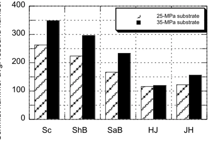
The Schmidt hammer soundings performed on the slabs right after surface preparation are summarized in Figure 4. As the recorded hammer rebound value is correlated to some degree to the hardness and strength of the material, it is again not surprising to see that irrespective of the surface preparation tech-nique, the average rebound values recorded on the slabs cast with the 35-MPa concrete are systemati-cally higher than those obtained on the 25-MPa sub-strates. The recorded rebound values show signifi-cant variability, as evidenced by the relatively high standard deviation numbers. This had to be ex-pected, given the intrinsic variability of the test and the high irregularity of the tested surface. Neverthe-less, the trends exhibited by the average Schmidt hammer results for the various investigated surface preparation techniques are somehow similar to those observed for the cohesion test results. It thus appears that except for surfaces with highly pronounced waviness, the Schmidt hammer can yield valuable information on the prepared substrate soundness, provided that the number and distribution of sound-ings are adequate.
0 100 200 300 400 Sc ShB SaB HJ JH 25-MPa substrate 35-MPa substrate Sch midt ham me r a vg . re b ou n d nu mb e r
Concrete removal technique
Figure 4. Results of Schmidt hammer (ASTM C805) soundings performed after surface preparation to evaluate the mechanical integrity of the exposed concrete surface.
3.1.3 Bond strength
The results of the various bond strength tests per-formed on the experimental slabs are presented in Figures 5 to 8.
Pull-off experiments
Except for the slabs prepared by jack hammering, the pull-off test results (Figure 5) are close to the corresponding substrate tensile strength values (see Table 1) for both slab series. In the 25-MPa slabs, where it is particularly close, failure of the pull-off
specimens occurred systematically in the substrate (again, except for the jack hammered slabs).
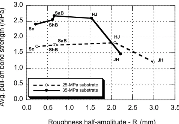
0.0 0.5 1.0 1.5 2.0 2.5 3.0 0.0 0.5 1.0 1.5 2.0 2.5 3.0 3.5 25-MPa substrate 35-MPa substrate Avg . pu ll-o ff b o nd st re ng th (MPa ) Roughness half-amplitude - Ra (mm) JH JH HJ HJ SaB SaB ShB ShB Sc Sc
Figure 5. Results of pull-off tests (ASTM C1583) performed after repair on the slabs treated with various surface prepara-tion techniques.
On jack hammered slabs, even though lightweight hammers (7-kg) were used, the recorded pull-off strength values are significantly lower and most of the time (> 90 %), failure occurred in the interface area. As for the corresponding weaker superficial cohesion strength values, this has to be attributed to the presence of disseminated defects left on the sur-face upon completion of the jack hammering opera-tions.
As far as the relationship between pull-off strength and substrate roughness is concerned, it appears that pull-off values slightly increase with the value of Ra,
provided that no or limited damage is induced. Where the extent of damage becomes significant, as in the case here of jack hammered slabs, the positive influence of increased roughness is completely off-set by the adverse effects of bruising.
As for the pull-off test results, the direct tensile test results obtained with the artificially profiled slab (Fig. 6) show that the average bond strength in ten-sion is increasing with the substrate roughness am-plitude. It clearly suggests that in absence of superfi-cially induced damage, increasing the surface of contact leads to a stronger repair bond.
Torsional experiments
The torsional shear bond test results are presented in Figure 7. Both in terms of magnitude and trends, they show similarity with the pull-off data. Again the substrate strength and the presence of damage are influential parameters. Contrarily to what could have been inferred, roughness does not appear to play a more important role in shear than in tension.
0.0 0.5 1.0 1.5 2.0 2.5 3.0 0.0 0.5 1.0 1.5 2.0 2.5 3.0 3.5 Avg . direct t en sion b on d strength (MPa ) Roughness half-amplitude - R a (mm)
Figure 6. Results of direct tensile tests performed after repair on cores extracted from the artificially profiled 25-MPa slab.
0.0 0.5 1.0 1.5 2.0 2.5 3.0 0.0 0.5 1.0 1.5 2.0 2.5 3.0 3.5 25-MPa substrate 35-MPa substrate Avg . to rsio n al b on d st re n gt h (MPa) Roughness half-amplitude - R a (mm) JH JH HJ HJ SaB SaB ShB ShB Sc Sc
Figure 7. Results of torsional bond experiments performed af-ter repair on the slabs treated with various surface preparation techniques.
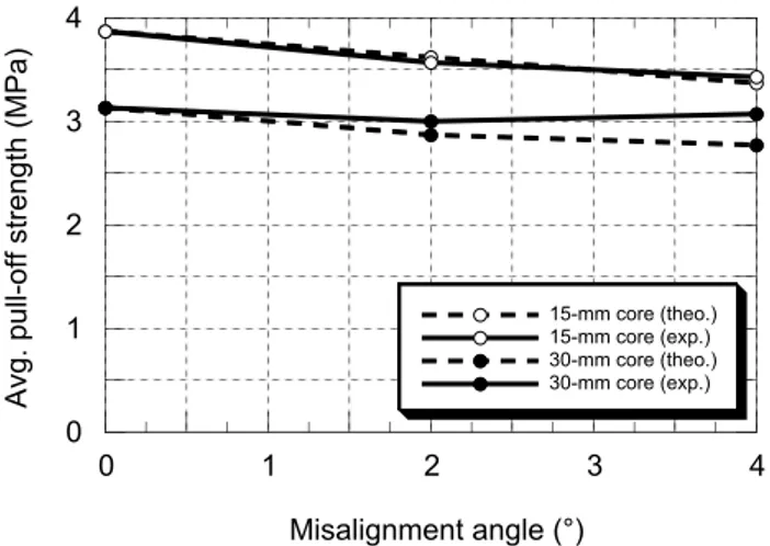
3.4 Effect of loading misalignment
The general trends observed in both numerical anal-ysis and experiments reveal that the pull-off strength values decrease as the misalignment angle increases (see Fig. 8). The deeper coring extends into the sub-strate, the greater is the effect of misalignment. Up to a certain misalignment limit angle assumed to be detectable by the average human eye (4° in the present study), load and coring misalignments were not found to yield significantly different stress fields and, for practical calculation purposes, they can be addressed in a similar manner. As for the failure mode, it can be concluded that within 4 degrees, testing misalignment does not significantly change the failure mode characteristics.
The simulation results provide a conservative, but realistic, lower bound limit for evaluation the influ-ence of misalignment on pull-off test results. A 2° misalignment can be expected to yield a pull-off strength reduction of 7 to 9 %, respectively, for 15
and 30 mm coring depths, and the corresponding de-crease resulting from a 4° misalignment reaches be-tween 13 and 16 %.
Figure 8. Comparison of predicted and experimental pull-off test results as a function of the misalignment angle.
The experimental pull-off test program results are, overall, consistent with the theoretical calculations, although the observed trends are not as clear, due to the experimental variability and to the added influ-ence of the coring depth.
From a practical standpoint, the results generated in this study indicate that when specifying a pull-off strength limit in the field, the value should be in-creased (probable order of magnitude: 10 to 15 %) to take into account the potential reduction due to test-ing misalignment.
3.5 Influence of moisture content
Both the ISAT (permeability index) and MCST test methods yielded relatively good correlations with the concrete moisture content, especially below 80 % RH.
ISAT test results were shown to be insensitive to concrete compressive strength, at least in the range of those tested. Results are influenced by the sub-strate surface quality, but it is difficult to conclude whether this is due to surface roughness, mi-crocracking, or a combination of both. The relatively high variation and dispersion characterizing the ISAT test results may stem from the difficulty of performing the test on rough concrete surfaces (for instance, after hydrojetting).
The MCST test yielded clearer trends and less dis-persed information than the ISAT test, as well as a better correlation with water content measurement (wet and dry weighing measurements).
Satisfactory correlation was also found between the water absorption index and the capillary absorption coefficients determined using both tests.
The influence of the susbtrate moisture content upon bond strength is illustrated for a polymer-modified repair mortar in Figure 9. Overall, for the repair sys-tems considered in this task, it appears that optimum saturation levels for repair bond strength would lie somewhere between 55 to 90 %.
Figure 9. Pull-off test results recorded for a polymer-modified repair mortar cast over concrete substrates at various saturation levels, with dry or wet polymer-modified slurry.
Clearly, additional work is required to identify a methodology that could be used in field applications and, furthermore, to assess more precisely and relia-bly what the optimum moisture ranges are for ce-ment-based repair materials.
3.6 Influence of carbonation
Experimental data on the influence of concrete sub-strate carbonation upon repair bond strength are pre-sented in Figure 10 for surfaces prepared by sand-blasting and jackhammering.
Figure 10. Pull-off test results recorded for test slabs repaired with 28-MPa concrete after different types of surface prepar-tion, with or without carbonation.
0 1 2 3 4 0 1 2 3 4 15-mm core (theo.) 15-mm core (exp.) 30-mm core (theo.) 30-mm core (exp.) Avg . p ul l-o ff st re ng th (MPa ) Misalignment angle (°) 0.0 0.5 1.0 1.5 2.0 2.5 3.0 3.5 4.0 40 50 60 70 80 90 100 Dry slurry Wet slurry Avg . p ul l-o ff bo nd st re ng th (MPa )
Saturation level in the substrate (%)
0.0 0.5 1.0 1.5 2.0 2.5 3.0 3.5 SaB JH Non-carbonated substrate Carbonated substrate Avg . p ul l-o ff bo nd st re ng th
For substrate surfaces prepared by sandblasting, no difference in bond strength is observed between car-bonated and non-carcar-bonated concrete substrates. Conversely, for substrates prepared with a concrete breaker, a significant reduction (16 %) in bond strength is found for carbonated surfaces as com-pared to non-carbonated surfaces. Such different ef-fects of carbonation could be attributed to the possi-ble micro-defects (bruising) of the surface prepared by chipping hammer. The limited number of tests performed using only one type of a repair material does not allow for conclusions about the overall ef-fect of carbonation on tensile bond strength. Differ-ent repair materials may not necessarily behave the same way in bond development to the carbonated surfaces.
It appears likely, though, that carbonation may have only a slight impact on bond strength for an other-wise sound, properly prepared concrete substrate surface.
4 CONCLUSION
The investigation has generated useful information for the evaluation and characterization of concrete surface preparation prior to repair.
Pull-off test is a convenient method for evaluating both the mechanical integrity of the concrete surface prior to repair and the repair bond strength. A relia-ble evaluation of these properties can be obtained, provided that a minimum number of tests are per-formed, with adequate equipment. When specifying a pull-off strength limit in the field, the value should be increased (by 10 to 15 %) to take into account the potential reduction due to testing misalignment. Bond strength of concrete repairs depends on a number of parameters. It has been shown that in ab-sence of substrate-induced damage, tensile bond strength increases with the substrate coarseness. Still, the most important parameter apparently re-mains the mechanical integrity of the substrate. In that regard, it must be stressed that the use of im-pacting methods such as jack hammering leaves sig-nificant damage at the surface, which can easily outweigh the benefits of an increased roughness. Other potentially important parameters upon repair bond development are the substrate moisture condi-tioning and state of carbonation at the time of cast-ing. The results obtained in the present study show that optimum moisture saturation levels for repair bond strength would lie somewhere between 55 to 90 %. Carbonation may in turn have only a slight impact on bond strength for an otherwise sound, properly prepared concrete substrate surface.
Based on the results of the research program report-ed in this paper, a document entitlreport-ed Suggestreport-ed
Guide Specification for Surface Preparation of Con-crete Prior to Repair and intended for repair and
overlaying with Portland cement concrete and pre-packaged cement-based materials was issued by the U.S. Bureau of Reclamation (Bissonnette et al., 2012).
ACKNOWLEDGMENTS
This project has been financially supported by the
Concrete Research Council of the American
Con-crete Institute (ACI), the Natural Sciences and Engi-neering Research Council of Canada (NSERC), the Québec FQRNT Research Fund and the industrial partners of the Industrial Chair on Durable Repair
and Optimized Maintenance of Concrete Infrastruc-tures at Laval University (BASF Building Systems,
City of Montreal, City of Québec, Euclid, Holcim, Hydro-Québec, King Packaged Materials, Lafarge, Ministry of Transportation of Québec, W.R. Grace & Co.), and through Scientific Cooperation Pro-grams of the Polish, Québec and Wallonia–Brussels governments.
REFERENCES
ASTM C39. 2005. Standard Test Method for Compressive Strength of Cylindrical Concrete Specimens, Annual Book
of ASTM Standards, Concrete and aggregates, volume
04.02, ASTM, West Conshohocken, PA, USA.
ASTM C469. 2002. Standard Test Method for Static Modulus of Elasticity and Poisson's Ratio of Concrete in Compres-sion, Annual Book of ASTM Standards, Concrete and
ag-gregates, volume 04.02, ASTM, West Conshohocken, PA,
USA.
ASTM C496. 2004. Standard Test Method for Splitting Tensile Strength of Cylindrical Concrete Specimens, Annual Book
of ASTM Standards, Concrete and aggregates, volume
04.02, ASTM, West Conshohocken, PA, USA.
ASTM C805. 2002. Standard Test Method for Rebound Num-ber of Hardened Concrete, Annual Book of ASTM
Stand-ards, Concrete and aggregates, volume 04.02, ASTM,
West Conshohocken, PA, USA.
ASTM C1583. 2004. Standard Test Method for Tensile Strength of Concrete Surfaces and the Bond Strength or Tensile Strength of Concrete Repair and Overlay Materials by Direct Tension. Pull-off Method), Annual Book of
ASTM Standards, Concrete and aggregates, volume 04.02,
ASTM, West Conshohocken, PA, USA.
BISSONNETTE, B.; COURARD, L. & VAYSBURD, A.M. 2006. Concrete removal techniques - influence on residual cracking and bond strength, Concrete International, 28(12), pp. 49-55.
BISSONNETTE, B.; VAYSBURD, A.M. & VON FAY, K.F. 2012. Best Practices for Preparing Concrete Surfaces Prior
to Repairs and Overlays, Report Number MERL 12-17, U.S. Bureau of Reclamation, Denver, CO, USA, 92 p. COURARD, L. & BISSONNETTE, B. 2004. Essai dérivé de
l’essai d’adhérence pour la caractérisation de la cohésion superficielle des supports en béton dans les travaux de réparation : analyse des paramètres d’essai, Materials and
Structures, 37(269), pp. 342-350.
CRD-C 164. 1992. Standard Test Method for Direct Tensile Strength of Cylindrical Concrete or Mortar Specimens, U.S. Army Corps of Engineers, Waterways Experiment Station, Vicksburg, MS, USA.
CSA A23.2-6B. 2000. Method of Test to Determine Adhesion by Tensile Load, CSA A23.2-00 Methods of Test for
Con-crete, Canadian Standards Association, Rexdale, ON,
Canada.
ICRI Guideline. 1997. No. 03732, Selecting and Specifying Concrete Surface Preparation for Sealers, Coatings, and Polymer Overlays, International Concrete Repair Institute, Des Plaines, IL, USA.