This is an author-deposited version published in:
http://oatao.univ-toulouse.fr/
Eprints ID: 8495
To link to this article: DOI: 10.1007/s00170-012-4597-y
URL:
http://dx.doi.org/10.1007/s00170-012-4597-y
To cite this version:
Ben Slima, Khalil and Penazzi, Luc and Mabru,
Catherine and Ronde-Oustau, François Fatigue analysis-based numerical
design of stamping tools made of cast iron. (2012) The International
Journal of Advanced Manufacturing Technology. ISSN 0268-3768
O
pen
A
rchive
T
oulouse
A
rchive
O
uverte (
OATAO
)
OATAO is an open access repository that collects the work of Toulouse researchers and
makes it freely available over the web where possible.
Any correspondence concerning this service should be sent to the repository
administrator:
[email protected]
Fatigue analysis-based numerical design of stamping tools
made of cast iron
K. Ben Slima&L. Penazzi&C. Mabru&F. Ronde-Oustau
Abstract This work concerns stress and fatigue analysis of stamping tools made of cast iron with an essentially pearlitic matrix and containing foundry defects. Our approach con-sists at first, in coupling the stamping numerical processing simulations and structure analysis in order to improve the tool stiffness geometry for minimizing the stress state and optimizing their fatigue lifetime. The method consists in simulating the stamping process by considering the tool as a perfect rigid body. The estimated contact pressure is then used as boundary condition for FEM structure loading anal-ysis of the tool. The result of this analanal-ysis is compared with the critical stress limit depending on the automotive model. The acceptance of this test allows calculating the fatigue lifetime of the critical zone by using the S–N curve of corresponding load ratio. If the prescribed tool life require-ments are not satisfied, then the critical region of the tool is redesigned and the whole simulation procedures are reacti-vated. This method is applied for a cast iron EN-GJS-600-3. The stress-failure (S–N) curves for this material is deter-mined at room temperature under push pull loading with different load ratios R0σmin/σmax0 −2, R 0 −1 and R 0 0.1. The effects of the foundry defects are determined by SEM observations of crack initiation sites. Their presence in tested specimens is associated with a reduction of fatigue lifetime by a factor of 2. However, the effect of the load ratio is more important.
Keyword Fatigue . Defects . Stamping . Tools . Cast iron
1 Introduction
Nodular cast irons are used in automotive car industry for stamping tools because of their high mechanical characteristics and easy manufacturing due to their high cast ability. These alloys present high fracture tough-ness, high fatigue limit (endurance), and a low produc-tion cost. Their characteristics allow using them as structural material for stamping tools [1, 2], mechanical parts [3–7], and pump part [8]. However, the complex geometry of the stamping tool entails the presence of foundry defect in their structure. These defects are the main fatigue life-limiting factors causing premature frac-ture of material [1, 6]. Some authors were interested in studying the fatigue behavior of this material [5, 7, 8] others in determining the effect of foundry defects on the fatigue behavior applied to other nuances of this material family [1, 6, 9, 10].
1.1 Stress analysis of stamping tools
In most general software of sheet metal forming, tools are considered as perfect rigid body. Several authors have aimed to reduce the spring-back [11,12] of sheet by the estimation of the plastic deformation of working surfaces and sub-surfaces of stamping tools. Other authors proposed to opti-mize the mass and the rigidity of the tool by topology optimization [13,14].
Firat et al. [11] have reported a maximal local stress of about 510 MPa and a maximal displacement of 0.86 mm for critical zones of a stamping tool under about 680 kN load-ing. This elastic stress was greater than the yield stress (400 MPa). To reduce the maximal local stress, authors optimized the stamping tool geometry for obtaining 350 MPa and 0.6 mm for maximal stress and displacement, respectively.
K. B. Slima
:
L. Penazzi:
F. Ronde-Oustau Université de Toulouse, ICA, Mines Albi, Campus Jarlard,81013 Albi Cedex 9, France C. Mabru (*)
Université de Toulouse, ICA, ISAE, BP 54032, 31055 Toulouse Cedex 4, France e-mail: [email protected]
In the case of topological optimization in order to im-prove the structure stiffness and to reduce the weight of the stamping tool, Nilsson et al. [13] chose to increase the level of Von Mises stresses from 110 to 140 MPa, to reduce the maximum displacement and the weight of the tool of about 15 and 20 %, respectively.
It therefore seemed that the estimate of the maximal stress and displacement of a stamping tool is a major ele-ment in the step design of tools. However, the fatigue of stamping tools is of major concern for optimal life designing and cycling assessments.
For the tools designed for a large production where the number of produced sheets is superior to 107cycles, the fatigue limit of material is generally employed as a data to be compared to the stress occurring in the tool. In the case of tools for limited production and with limited fatigue lives (where the number of cycles ranges from 105 to 107 cycles), the previous approach is very conservative and restricts the possible optimization concerning weight and rigidity. Taking into account the fatigue stress for a given lifetime (corresponding to the given number of sheets that the tool is supposed to produce) in the design process would then lead to improve the optimization. This will be done in the methodology proposed in the present paper.
1.2 Tools material
Only few works found in the literature concern the materials of working surfaces and structure of the stamping tools of bodywork components. The technical guides of French car manufacturers CNOMO (http://www.cnomo.com, December 2010, EM24.15.050) recommend the choice of tools materials linked to the application type, the sheet dimension and ma-chining parameters, or the cost of tool. The choice of the material grade can also be linked to specifications of the surface hardness and therefore to the capacity of the micro-structure to attain these characteristics by heat treatment (T7). For automotive tools of bodywork subjected to fatigue solicitation in transition regime near the fatigue limit (105–107 cycles), the rule CNOMO recommends the use of cast iron EN-GJS-600-3. Griswold [3], Hubner [4], and Abebe [8] reported the use of this alloy for the manufacturing of components in the automotive industry. The authors presented the mechanical properties of this alloy for monotonic and fatigue experiments with a load ratio R0−1. In another study, Shirani [15] showed that the load ratio and the specimen diameter have an influence on the fatigue behavior of a cast iron EN-GJS-400.
In order to include fatigue stress data in the optimi-zation process, it is then necessary to increase knowl-edge on the fatigue behavior of EN-GJS-600-3 alloy and in particular to study the influence of the load ratio. In the present work, the analysis of the first results of
tool structure analysis shows that the load ratio is not constant in the stamping tool. So for recovering a large range of the material behavior, fatigue tests will be conducted with three different load ratios and the S–N curve will be established for each studied load ratio.
1.3 Design methodology
During the last decade, a considerable progress has been accomplished in results post-treatment of stamping numer-ical simulation allowing to achieve the local loading instead of the global ones [14]. These local loads (the local contact pressure at sheet/tool interface [1, 16]) can be used as boundary conditions for numerical simulation of mechanical solicitations of tool considering the nodal efforts [11]. Del Pozo [17] proposed a methodology to determine the maxi-mal displacement of the different part of the stamping tool while considering the group die-press (composed by the different parts of the stamping tool as die, punch, and blank holder, assembled with a simplified press model) as a de-formable body. So, this methodology is very costly in CPU time calculation for the used stamping tools because of their large dimensions. In the present paper, the proposed meth-odology for stamping tools design allows predicting inde-pendently the stress state in any part of tools. It consists in coupling the stamping numerical processing simulation and structure analysis by using the maximum contact pressure in the interface tool/sheet as boundary conditions for FEM structure loading analysis of the tool. So this procedure will permit to reduce the CPU time calculation and to improve the precision of tool structure analysis.
2 Design procedure
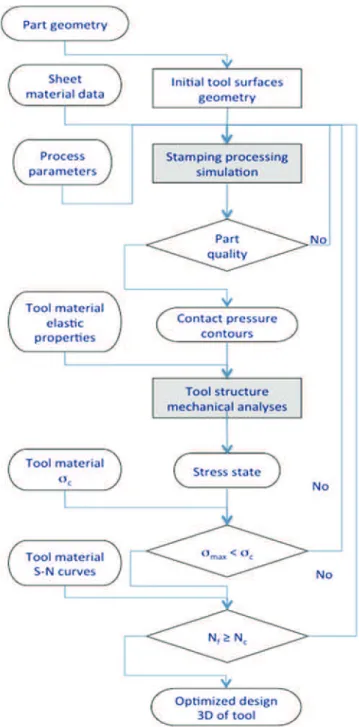
In automotive industry, the simulation of stamping process is realized by Autoform© or PAMSTAMP©. This study is realized in collaboration with the automotive industrial PSA Peugeot Citroen. The simulation of stamping process is realized, generally by Autoform© and occasionally by PAMSTAMP© in the more complicated cases. Only the tool can be considered as rigid body in this software. However, the simulation of the stamping process with a deformable tool in Abaqus© (software used by the industrial partner for stress analysis) or any FEM codes requires an enormous calculation time and this software does not allow giving a precision as Autoform© or PAMSTAMP©. To reduce the calculation time of the process and tool design, a new methodology of stamping tool calculation is proposed. Its flowchart is presented in Fig.1. At first step, the procedure consists in designing the tool geometry from the part geom-etry to be produced, and in simulating the stamping process by considering the tool as a perfect rigid body. The initial
tool surface can be modified if the prescribed stamping quality requirements are not satisfied and the whole simula-tion procedures are then reactivated. The second step con-sists in using the maximum contact pressure, obtained by numerical simulation of stamping process, as boundary con-dition for structure loading FEM analysis (Figs. 2 and 3). The material is considered as an isotropic elastic material with an elastic modulus of 170 GPa and Poisson’s ratio of 0.25. Then, the general state of stress is analyzed and the maximal stress is compared with the critical maximal stress σcof the tool material. In this case, the cast iron EN-GJS-600-3 is used. The critical stress is considered as
conventional yield stress obtained by monotonic tests; it is equal to 408 MPa in traction and −449 MPa (Table1) in the compression case. If the maximal stress is lower than σc, the
calculation of the lifetime of the tool critical zones is per-formed via experimental S–N fatigue curves with various load ratios. The choice of the critical number of cycle Ncis
linked to the type of automotive car. The acceptance of this second criterion allows validating the tool geometry. Other-wise, if one of both criteria fails, the critical region of the tool is redesigned and the whole simulation procedures are reactivated.
3 Initial tool structure analysis
As part of the design process, the stamping tool must be analyzed for the various loads that it will experience during its service life. A prime purpose is to assess whether the tool will be able to resist these loads.
Fig. 1 Flowchart of the proposed procedure
Fig. 2 Maximum contact pressures in the sheet: results of stamping simulation used as reference of tool structure analysis (Courtesy of PSA Peugeot-Citroen)
Fig. 3 Part used in this study:(a) Finite elements mesh of the section of stamping tool, (b) maximum contact pressure applied on upper face
3.1 Load cases
The main load case to be considered is the pressing phase with the maximum level of punching effort. The contact pressure on sheet/tool interface is obtained by stamping process numerical simulation as can be observed in Fig. 2
(Autoform©). A maximum value of 170 MPa is observed in some radii but average value of 20 MPa is observed on planar faces. These data are used as initial boundary con-ditions for the tool structure analysis. Other load cases, such as clamping of blank holder or the tool handling, also may be taken into account.
3.2 Studied case
In order to minimize the CPU time calculations, only a short section (Fig. 3), of the stamping tool is considered. Due to the wall thickness of the tool, about 40 mm minimum, a short section of 35 mm wide has been chosen. A mesh with about 38,000 nodes and 20,000 elements is obtained. Two load cases are studied: (1) stamping case at maximum punch force and (2) gravity case. An isotropic elastic behavior is considered. The bottom face of the section is fixed. Four-node tetrahedral elements, type C3D4, are used to mesh the part. The size of the elements is around 5 mm. The structure analysis is performed with the software Abaqus© Standard V6.9.
3.2.1 Stamping load
The pressure load defined by the contact pressure obtained by the stamping processing simulation (Fig.2) is applied on the elements of the active face. A Perl programming language has been developed to read “Maximum contact pressure” on tool–sheet interface, stored at sheet nodes, and write the pressure on the elements at the upper face of tool model. Perl is an interpreted programming language adapted to manipu-lation of files and for data treatment. Perl takes up features from programming languages C, shell scripting. The mean value is around 20 MPa and the maximum pressure is about 170 MPa (Fig.3). The lower face of the part model is embed-ded. The results of stress analysis are illustrated in Figs.4and
5, showing respectively the Von-Mises equivalent stress dis-tribution σeqand the principal maximal stress σ33.
A maximum equivalent stress of 210 MPa is observed in the upper radius on internal face of tool (Fig. 4). The
analysis of all components shows an almost uniaxial state of stress. The map of the σ33 stress component shows a
lower value close to −220 MPa (Fig.5). This stamping case defined a minimum value of stress, σmin0 −220 MPa. The absolute value of the minimum stress (or maximum Von Mises equivalent stress) is less than yield stress Rp02
(Table1). From a static strength point of view, the material behavior remains elastic and the maximal stress remains inferior to material critical stress.
3.2.2 Handling load
A second load case consists in considering the stresses generated by the own weight of the tool (gravity case), in this case the whole tool is subjected to its own weight (2.3 tons). The results lead to a very weak maximal stress, about 0.1 MPa at any points of the tool.
Table 1 Mechanical properties of the nodular cast iron EN-GJS-600-3 E (GPa) Rp0.2 trac(MPa) Rp0.2 comp(MPa) σU(MPa) A (%) 169 408 449 640 3.6
Fig. 4 Result of calculation: Von-Mises stress distribution
4 Material investigations
4.1 Material and mechanical properties
The chemical composition of EN-GJS-600-3 as determined by EDSX is (in wt%) 3.3 C, 0.168 Mn, 1.14 Si, 0.02 S, 0.06 Cr, 0.06 Ni, 0.04 P, and 0.0157 Mo. The microstructure of the investigated material consists of an essentially pearlitic matrix with bull’s eyes structure identified by the nodular graphite surrounded by a ferrite zone (Fig.6).
Monotonic and fatigue tests were carried out on cylindri-cal specimens with 9 mm diameter and a gauge length of 25 mm, as illustrated in Fig.7. Tensile and compressive tests were performed with a strain rate of 10−2s−1 and 10−3s−1,
respectively. Strain measurements were completed thanks to an extensometer with a gauge length of 12 mm.
The results from monotonic tests are reported in Table1.
4.2 Fatigue experiments
The choice of the load ratio (R0σmin/σmax) to be considered
in calculation of the lifetime of the tool critical zones via experimental S–N curves is given by the values of minimum and maximum stresses at the same point for all load cases considered. In the example reported here, the minimum stress by the stamping load case is σmin0 −220 MPa in upper radius on internal face of tool. The maximum stress is given by the gravity load case σmax0 0.1 MPa. This leads to a load
ratio equal to −2,200. Our hydraulic machine and the spec-imen geometry were not suitable for such load ratio. How-ever, for other tool geometry and/or other load cases, the load ratio for critical zones could be different. Consequently, fatigue tests were carried out at room temperature with various load ratios in order to explore the effect of load ratio as noted in the literature [15].
For the components and zones working in compression a load ratio R0−2 was chosen. The R00.1 was chosen for the components and zones working in traction as die of stamp-ing tool, finally the load ratio R 0−1 was studied for
comparing our results with other authors and to represent the zones with a symmetric loading. The studied stresses range varies from 280 to 400 MPa for the load ratio R0−2, from 250 to 360 MPa for R 0−1 and between 140 and 190 MPa for R00.1. Two to eight tests were performed for each stress level.
The frequency in industrial application is about 0.3 Hz (20 strokes per minute) and the required lifetime is between 105and 107cycles. To reduce the time of material charac-terization in this fatigue study, a conventional value of 10 Hz was chosen.
4.3 Results and discussion
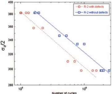
Figure8shows S–N curves for fatigue tests with a load ratio R0−2. SEM observations of the initiation site on the frac-ture surfaces in cast iron specimens, allowed identifying the crack initiation origin. Two groups of specimens were then distinguished: specimens with crack initiation on foundry defects between 100 μm and 1 mm (Figs. 9 and 10) and specimens with crack initiation due to the debonding of nodular graphite in surface (Fig. 11). This last group of specimens is called “without defects” in the following and in Fig. 8 while the first one is called “with defects.” The
Fig. 6 SEM micrographs of the microstructure of the cast iron ENG-GJS-600-3
Fig. 7 Specimen geometry
Fig. 8 S–N curves of the cast iron EN-GJS-600-3 with and without foundry defects with a load ratio R0−2
specimens with defects show a reduced fatigue life divided by 2 compared to the specimens without defects. Micro-shrinkages (Fig.9) or big grain of graphite (Fig.10) near the surface were the main causes of crack initiation in the specimen with defects.
The Basquin model is used to represent S–N curves; it is defined by the following equation:
σa=2¼σ
0
f # 2Nð Þ b
ð1Þ where σais the stress amplitude, Nf the number of failure
cycles and σ′f and b are respectively the fatigue strength
coefficient and fatigue strength exponent. Two distinct sets of parameters are then identified for this load ratio to repre-sent the two groups of specimens (lines in Fig.8).
For the specimens tested at R0−1, SEM observations of fracture surfaces did not bring forward two types of crack initiation sites. All the fracture surfaces exhibited “defects” such as those of specimens with defects tested at R0−2.
However, the results of fatigue tests at R0−2 permitted to create the hypothesis of the reduction of fatigue lifetime by a factor of 2 associated with the presence of foundry defects with a size between 100 μm and 1 mm. So, this hypothesis is applied to the case of fatigue test results with a load ratio R0−1. Basquin law is then used to model an S–N curve corresponding to specimens without defects for such load ratio. Experimental results for specimens with defects and results provided by this model for specimens without defect are then compared with S–N curves obtained by other authors [2, 7, 8] on the same material for the same load ratio. It is shown in Fig.12. A good correlation between the predicted curve without defect of load ratio R0−1 and the reported Basquin curves from other experimental studies, is observed. So, this hypothesis can be validated and applied to other load ratios for this material
Fig. 9 SEM observations of the initiation site on the fracture surface in cast iron specimens containing a foundry defect: micro-shrinkage in surface
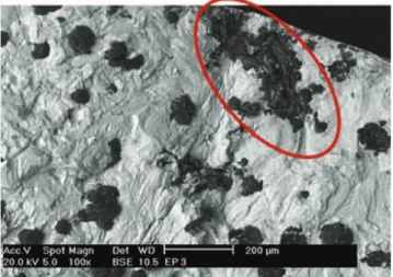
Fig. 10 SEM observations of the initiation site on the fracture surface in cast iron specimens containing a foundry defect: big grain of graphite (800×150 μm)
Fig. 11 SEM observations of the initiation site on the fracture surface in cast iron specimens: debonding of nodular graphite in surface
Fig. 12 Comparison of experimental and predicted S–N curves with other authors for the cast iron EN-GJS-600-3 with a load ratio R0−1
Then, the validation of this hypothesis allowed to predict the S–N curve without defects of the load ratio R 00.1 from S–N curve of material containing foundry defects (Fig. 13). Table 2 shows the comparison of Basquin parameters of studied load ratios for the cast iron EN-GJS-600-3 with and without foundry defects. Furthermore, these results are compared with other authors at the load ratio R 0−1. For this case, the Basquin parameters of this study are slightly smaller in com-parison with literature results with different slopes for the same load ratio.
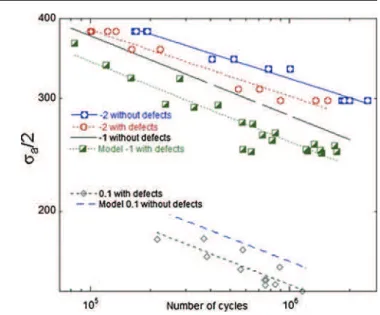
The analysis of the fatigue test results with different load ratios (Fig. 14) shows the effect of this parameter is much more important than the presence of foundry defects. The difference of fatigue lifetime between R 0−1 and R0−2 is around a factor of 4. It can reach a factor of 40 between R 0−1 and the extrapolation of the S–N curve with a load ratio R00.1. So, it is very important to use the S–N curve with a correct load ratio for calculating fatigue lifetime of components. It is recommended to apply an S–N curve with a negative load ratio in the case of geometrical zone working in com-pression and a positive load ratio to geometrical zone solicited in tension.
5 Fatigue stress analysis
With the stress results σmin0 −220 MPa and Eq. 1 in the case R0−2 with defects, the fatigue lifetime was estimated about 5.108cycles. Faced with this result, a first solution is to validate the tool design (Fig.1). But if this tool is used for the manu-facturing of 106 parts, the estimated lifetime is 500 times greater. The tool is over dimensioned. Another solution is to introduce a topological optimization phase in the design meth-odology in order to improve the structure stiffness and to reduce the weight of the stamping tool. To obtain a lifetime of 106 cycles, the minimal stress can then reach σmin0 −400 MPa.
6 Conclusion
In this paper, a design procedure of stamping tools was pro-posed. The originality of the proposed approach is to take into account the service loads of the tool (by handling and strikes in press) and the fatigue design. Service charges related to the strike to press were obtained using the results of contact pressure at the interface sheet/tool from a numerical simula-tion of the stamping operasimula-tion. These pressures were used as boundary conditions for the structure analysis of tool. Fig. 13 Experimental and predicted S–N curves for the cast iron
EN-GJS-600-3 with a load ratio R00.1
Table 2 Comparison of Basquin parameters from differ-ent sources with load ratio R0−1, R0−2, and R00.1
Local ratio R0−1 R0−2 R00.1 σ′f b σ′f b σ′f b Specimen with defects 1,453 −0.12 1,258 −0.1 828 −0.12 Specimen without defects 1,585 −0.12 1,266 −0.1 901 −0.12 Lagoda 2001 [2] 1,131 −0.1
Abebe 2008 [8] 978 −0.09 Germann 2010 [7] 1,020 −0.094
Fig. 14 Comparison of experimental S–N curves with different load ratios for the cast iron EN-GJS-600-3
The proposed methodology was applied to a simplified case of a stamp. The contact pressure sheet/tool calculated at the end of strike allowed the evaluation of the stress state in the tool. This was mainly uniaxial compression with a value of −220 MPa. In order to include fatigue analysis in the design procedure, the fatigue of cast iron EN-GJS-600-3 was studied at room temperature. The SN curves of this material were established with load ratios R0−2, −1, and 0.1. The SEM micrograph allowed to study the crack initiation and to identify two groups of fracture origins. In the case of material without defects, a debonding of nodular graphite in surface causes crack initiation. However, some micro-shrinkages and big grains of graphite near the outer surface are the main cause of crack initiation in the material with defects. Presence of foundry defects with a size between 100 μm and 1 mm in the 9 mm diameter of specimen is associated with a reduction of fatigue lifetime by a factor of 2. However, this factor is more accentu-ated by the load ratio effect that can reach a factor of 40.
In the application case considered in the present paper, the load ratio encountered by the critical sites of the tool was highly negative. The Basquin curve associated to the lower load ratio explored for the fatigue tests was then used. For specimens with defects, R0−2 Basquin curve showed the stress state in the tool leads to a fatigue lifetime around 109 cycles. This result validates the current design of the tool. It can also lead to an optimization approach to reduce weight and increase stiffness.
Acknowledgments The authors thank the DGCIS of French Minis-try of IndusMinis-try and the competitive pole iD4CAR for the funding for this work in the EMOA (“Excellence dans la Maitrise des Ouvrants Automobiles”) project, PSA Peugeot Citroen for all the facilities and collaboration in the project. The authors acknowledge Thomas Papaix and Serge Tovar for technical support
References
1. Benslima K, Penazzi L, Mabru C, Ronde-Oustau F, Rezai-Aria F (2011) A new method for advanced virtual design of stamping tools for automotive industry: Application to nodular cast iron
EN-GJS-600-3. In: ESAFORM 2011, AIP Conference Proceedings, pp. 1713–1720
2. Lagoda T (2001) Energy models for fatigue life estimation under uniaxial random loading. Part II: verification of the model. Int J Fatigue 23(6):481–489
3. Griswold FD, Stephens RI (1987) Comparison of fatigue proper-ties of nodular cast iron production and Y-block casting. Int J Fatigue 9(1):3–10
4. Hubner P, Pusch G, Krodel L (2004) Fatigue behaviour of cast iron with globular graphite. Adv Eng Mater 6(7):541–544
5. Meggiolaro MA, Castro JTP (2004) Statistical evaluation of strain-life fatigue crack initiation predictions. Int J Fatigue 26(5):463– 476
6. Nadot Y, Mendez J, Ranganathan N (2004) Influence of casting defects on the fatigue limit of nodular cast iron. Int J Fatigue 26 (3):311–319
7. Germann H, Starke P, Kerscher E, Eifler D (2010) Fatigue behav-iour and lifetime calculation of the cast irons GJL-250, EN-GJS-600 and EN-GJV-400. Procedia Eng 2(1):1087–1094 8. Abebe BH (2008) Fatigue life assessment of a diesel engine pump
part subjected to constant and variable amplitude loading. Master thesis, Bauhaus University
9. Beretta S, Blarasin A, Endo M, Giunti T, Murakami Y (1997) Defect tolerant design of automotive components. Int J Fatigue 19(4):319–333
10. Costa N, Machado N, Silva FS (2010) A new method for predic-tion of nodular cast iron fatigue limit. Int J Fatigue 32(7):988–995 11. Firat M (2007) Computer aided analysis and design of sheet metal forming processes: part III: stamping die-face design. Mater Des 28(4):1311–1320
12. Ledoux Y, Sebastian P, Samper S (2010) Optimization method for stamping tools under reliability constraints using genetic algo-rithms and finite element simulations. J Mater Process Technol 210(3):474–486
13. Nilsson A, Birath F (2007) Topology optimization of a stamping die. In: NUMIFORM 2007, Conference Materials Processing and Design: Modeling, Simulation and Applications 908, pp. 449– 454
14. Gentili A, Penazzi L, Di Pasquale E (1998) Topology optimization in sheet metal forming tool design. In: IDMME’98, pp. 449–456 15. Shirani M, Härkegård G (2011) Fatigue life distribution and size
effect in ductile cast iron for wind turbine components. Eng Fail Anal 18(1):12–24
16. Oudjene M, Batoz JL, Penazzi L, Mercier F (2006) A methodology for the 3D stress analysis and the design of layered sheet metal forming tools joined by screws. J Mater ProcessTechnol 189(1– 3):334–343
17. del Pozo D, Lopez de Lacalle LN, Lopez JM, Hernandez A (2006) Machining of large dies based on the prediction of the press/die deformation. In: Intelligent production machines and systems 2nd I*PROMS Virtual International Conference, pp. 83–88