HAL Id: hal-02384277
https://hal.archives-ouvertes.fr/hal-02384277
Submitted on 28 Nov 2019HAL is a multi-disciplinary open access archive for the deposit and dissemination of sci-entific research documents, whether they are pub-lished or not. The documents may come from teaching and research institutions in France or abroad, or from public or private research centers.
L’archive ouverte pluridisciplinaire HAL, est destinée au dépôt et à la diffusion de documents scientifiques de niveau recherche, publiés ou non, émanant des établissements d’enseignement et de recherche français ou étrangers, des laboratoires publics ou privés.
Parametric Optimisation of a Trigenerative Small Scale
Compressed Air Energy Storage System †
Mohamad Cheayb, Sébastien Poncet, Mylène Marin Gallego, Mohand
Tazerout
To cite this version:
Mohamad Cheayb, Sébastien Poncet, Mylène Marin Gallego, Mohand Tazerout. Parametric Optimi-sation of a Trigenerative Small Scale Compressed Air Energy Storage System †. Proceedings, MDPI, 2019, 23, �10.3390/proceedings2019023005�. �hal-02384277�
Proceedings 2019, 23, 5; doi:10.3390/proceedings2019023005 www.mdpi.com/journal/proceedings
Proceeding
Parametric Optimisation of a Trigenerative Small
Scale Compressed Air Energy Storage System
†Mohamad Cheayb 1,*, Sébastien Poncet 1, Mylène Marin-Gallego 2 and Mohand Tazerout 2 1 Department of Mechanical Engineering, Université de Sherbrooke, Sherbrooke, QC J1K 2R1, Canada 2 Department of Energy Systems and Environment, IMT Atlantique, Nantes 44 307, France
* Correspondence: [email protected]
† Presented at the 27th Canadian Congress of Applied Mechanics, Sherbrooke, QC, Canada, 27–30 May 2019. Published: 23 August 2019
Abstract: Recently, major improvement on compressed air energy storage technology has been made
by using the heat of compression for heating energy or using it to preheat the compressed air in the expansion phase and by demonstrating its ability to produce cooling energy. Thus, the trigenerative compressed air energy storage has been introduced. In this paper, we introduce a configuration of trigenerative compressed air energy storage system giving the preference to the electric energy production. The study then focuses on undertaking an optimization study via a parametric analysis considering the mutual effects of parameters. This analysis is applied to a micro-scale application including the existing technological aspects. The parametric study results applied on the hot temperature of the thermal energy storage indicate the possibility to find an optimal solution as a trade-off between system performances and other parameters reflecting its cost. On the contrary, the selection of the maximal storage pressure cannot be achieved by finding a compromise between energy density and system efficiency. A complete study of other design parameters will be addressed in a future publication.
Keywords: trigenerative compressed air energy storage; parametric study; micro-scale application;
thermodynamic modeling
1. Introduction
Electrical energy storage (EES) becomes a vital aspect to ensure load-energy balance when integrating renewable energy resources [1,2]. Among EES technologies, adiabatic compressed air energy storage A-CAES is a very promising technology. Its concept is based on storing the electricity by compressing the ambient air and store it in the form of compressed air and thermal energy, the energy is released by heating the air before it expands in the turbine. The round trip efficiency of the system is expected to be 70% [3–5].
Recently, it has been demonstrated that A-CAES concept can be modified in order to produce additionally heating and cooling energy, hence the trigenerative compressed air energy storage T-CAES has been introduced [6–11]. Many configurations has been proposed which differs on how the compression heat is used in the expansion. The values of electric efficiency found by those studies ranges from 30% to 57% and the overall performance coefficient is improved by the cogeneration of heat and cold in the range of 20–30% as reported by Liu and Wang [7].
Many studies on A-CAES or T-CAES focused on the optimization of the performances by investigating the effect of the design parameters. The potential improvements could be achieved by increasing the number of compression and expansion stages [6,12], the effectiveness of heat exchangers [10], the arrangement of compressors and expanders from parallel to series [13], the maximum storage pressure [7] and the operation of expanders under variable pressure [10].
Proceedings 2019, 23, 5 2 of 7
Many studies proved that the main sources of the inefficiency of the system are the turbine and compressors efficiencies [12,14,15] and the exergy destruction in the throttling valve [14,16].
However, in these studies, the effect of each parameter is dissected without paying attention to their possible mutual effect or interaction and accounting for all evaluation criteria used to assess the electrical energy storage technologies. The main purpose of this paper is to present an approach based on detailed thermodynamic model, which helps to figure out the mutual effect of the parameters, on selected evaluation criteria such as energy density, heat exchanger footprints, roundtrip electric efficiency and the comprehensive efficiency. This approach is applied on the effect of the hot temperature of the thermal energy storage and the maximum storage pressure on the performances of a proposed configuration of micro scale T-CAES.
2. Methodology
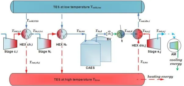
In this study, the configuration proposed of the small-scale T-CAES is shown in Figure 1. The charging phase is composed by multistage compressors with intercooling in order to increase the compression efficiency and the compressed air is cooled before storing to increase the energy density. During the discharging phase the pressure of the air stored is reduced by a throttling or expansion valve (EV) before the turbine. This configuration is based on maximizing the electric efficiency so that the inflow air of the first expansion stages is preheated and the last stage is dedicated to produce cooling energy.
Figure 1. Schematic of the proposed trigenerative compressed air energy storage system.
The model of the air-side components validated experimentally by Cheayb et al. [16] is adopted. The model of heat exchangers HEX, air turbines and TES basing on conservation of mass and energy is added. The main assumption used are as follow:
• Air is considered as an ideal gas.
• The pressure losses in HEX of discharge phase are neglected compared with the losses in HEX
of discharge phase.
• The air input temperature of the first HEX in the discharge phase is considered at the ambient
temperature.
• The temperature of the cold TES reservoir in the charging phase is at the ambient temperature. Cutting edge technology of small scale turbine developed in [17] which operates at 25 bars could be employed for the first stages and an air motor for the last stage due its low cost and adaptability to small scale applications [16,18]. Besides, pressurized water is selected as thermal energy storage TES medium.
In order to be able to produce the cooling energy from the air motor and simplify the design, the output temperature of each expansion stage should be close to the ambient temperature. Imposing the hot temperature of TES, the optimal number of expansion stages 𝑁e,optimal corresponds to the maximum input temperature of each turbine. Hence, 𝑁e,optimal is the minimum number of stages, which can satisfy the above condition and it can be found by an iteration procedure. This makes a good contribution to relate the number of expansion stages to the compression stages and other design parameters.
The whole thermodynamic model is implemented on MATLAB. It includes a set of fixed and variable input/output parameters. The fixed ones are selected to satisfy the need of a micro-scale electric load ranging from 1 kW to 2 kW, with respect to the technical constraints and the specific data of the manufacturer of each component. On the other hand, the variable parameters such as the heat exchanger effectiveness, the hot temperature of TES, the maximum storage pressure, the number of compression stages are varied one at time if they are independent, or many of them at the same time otherwise. For instance, if the number of compression stages is changed the hot temperature of TES is dependent on it and considered as an output variable parameter. This procedure allows to investigate the impact of each parameter on other and on the whole system performances. This is towards finding an optimal design solution of the system.
The system is assessed on the basis of the electric efficiency and the comprehensive efficiency (introduced by [8]) expressed in Equations (1) and (2), and other criteria which reflect the cost of the system such as heat exchanger footprints, the number of stages and the energy density defined by Equation (3).
𝜂 = 𝐸 ,
𝐸 , (1)
where 𝜂 is the roundtrip electrical efficiency, 𝐸 , is the electric energy of compression and
𝐸 , is that for expansion:
𝜂 = 𝑄 𝐶𝑂𝑃 , + 𝑄 𝐶𝑂𝑃 , + 𝐸 , 𝐸 , (2)
where 𝜂 is the comprehensive efficiency, 𝑄 and 𝑄 denote the heating and cooling
energies, 𝐶𝑂𝑃 , and 𝐶𝑂𝑃 , are the performance coefficients of conventional heat pump
functioning on heating and cooling modes respectively.
𝐸 = 𝐸 , ,
𝑉 (3)
where 𝐸 is the energy density and 𝑉 is the volume of air in the storage tanks.
3. Results and Discussions
In this section, we apply the parametric study in two important parameters, which are the hot temperature of thermal energy storage and the maximal storage pressure. The investigation of the other parameters will be the subject of a future publication.
3.1. Effect of Hot TES Temperature
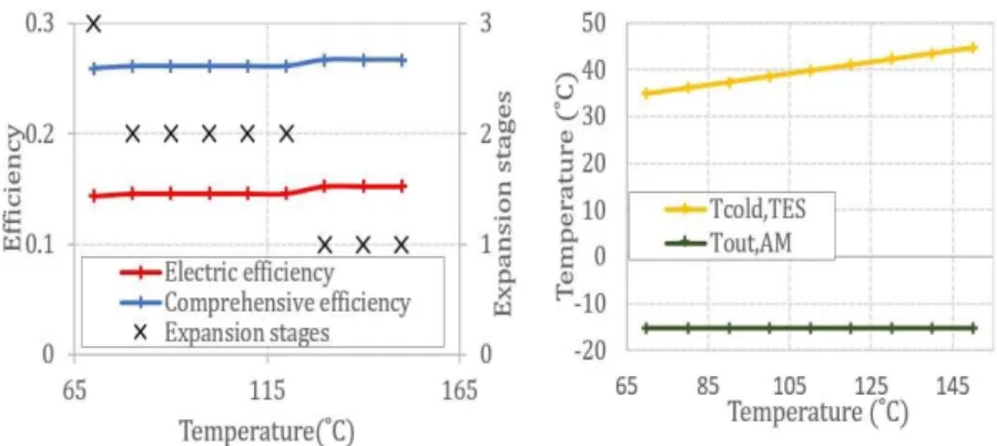
By setting the number of compression stages to three, the maximum storage pressure to 200 bar and the effectiveness of HEX to 0.85, the resulting variation of the global system efficiencies, the required number of expansion stages and the temperature of the cold TES and the output temperature of AM (Air Motor) are presented in Figure 2. The required HEX footprints are shown in Figure 3.
In Figure 2, the number of expansion stages 𝑁e decreases at some critical values as 𝑇h,TES increases, while the system efficiencies increases too slowly only on the basis of these values. This is due to the fact that the input temperature of each turbine stage and subsequently the preheating energy changes only at the critical values of 𝑇h,TES in order to satisfy the condition of an output expansion stage temperature equals of the ambient.
Proceedings 2019, 23, 5 4 of 7
Figure 2. T-CAES efficiencies and the optimal number of expansion stages (left) and the temperature
output of AM and of the cold TES (right) as a function of the temperature of hot TES.
At constant 𝑁e, the HEX footprints of the discharging phase decrease substantially (Figure 3) since the logarithmic mean temperature LMTD grows, assigned to the rise of the water output temperature of TES (Figure 2). The maximum values of HEX footprints are achieved at the critical values of hot, TES with a general declining trend due to the decrease of 𝑁e. The variation of the total footprint follows that of the discharging phase HEX footprints tendency given the small rise of the HEX footprints of the charging phase.
To sum up, the hot temperature of TES affect marginally the efficiencies of the system which proves the results of Budt et al. [19] based on simple thermodynamic analysis. An accurate choice should be based on minimizing the number of expansion stages and heat exchanger footprints, thus in this example optimal ranges of 𝑇h,TES are between 110 and 120 °C or between 140 and 150 °C.
Figure 3. Required HEX footprints as a function of the temperature of TES.
3.2. Effect of the Maximum Storage Pressure
In this case, the number of compression stages are fixed to two and 𝑇, is chosen the maximum possible according to the compression ratio respecting the following condition.
For intercooling HEX:
𝐶 = 𝐶 (4)
where 𝐶𝑚𝑖𝑛 = 𝑚𝑎,𝑐𝐶𝑝,𝑎 and 𝐶𝑚𝑎𝑥 = 𝑚𝑤,𝑐ℎ,𝑖𝐶𝑝,𝑤, 𝑚𝑎,𝑐 and 𝑚𝑤,𝑐ℎ,𝑖 are the air mass flow rates of
compressed air and water in each HEX of the charging phase respectively. 𝐶𝑝,𝑎 and 𝐶𝑝,𝑤, denote the heat capacity of air and water.
The simulation results are shown in Figures 4 and 5. It is obvious that the mass stored is directly proportional to the maximum storage pressure, thus the energy density rises linearly as the maximum pressure increases (Figure 4). The discharge time increases as the mass stored increases. In the other hand, the increase of the global pressure ratio and the stored air for a fixed power input induces a decline of the charging time. As a result, as shown in Figure 4, the discharge to charge time ratio decreases mostly at the beginning (from 30 to 170 bars).
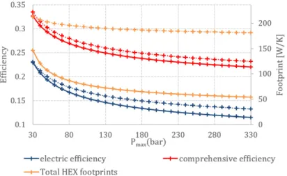
In Figure 5, the comprehensive and the electric efficiency decrease sharply as the maximum storage pressure increases from 30 to 130 bars, then they decrease at a moderate rate. This is mainly due to the increase of the compression energy related to the compression ratio power 0.2 (taking the polytropic coefficient equals to 1.25). The total HEX footprints decreases also since the LMTD increases.
In the optimal scenario, the maximum value of the electric efficiency is at 23% and the comprehensive efficiency is much higher at 32.6%. The low values are mainly related to the poor performances of the machinery at micro scale. For instance, the turbine efficiency is at 62% and of the AM is 30%. However, the cogeneration option enhances the round trip efficiency in the order of 10.5%. To conclude, the maximum storage pressure plays a major role on the system efficiency, but there is not a trade-off between the efficiency and the energy density.
Figure 4. Discharge to charge time ratio and energy density as a function of the maximum
storage pressure.
Figure 5. T-CAES efficiencies and the total HEX footprints as a function of the maximum
storage pressure.
4. Conclusions
The paper presents a procedure which is able to optimize the performances of a trigenerative compressed air energy storage system via a parametric study focusing on the mutual effects of the parameters.
Based on a thermodynamic model, the effects of hot thermal energy storage temperature and the maximum storage pressure are discussed. The main conclusions which can be drawn are:
1. 𝑇h,TES has a minor effect on the system performances, whereas it must be chosen such that to
minimize the number of expansion stages and heat exchangers footprints.
2. The maximum storage pressure plays a leading role on the system efficiency and energy density. 3. For microscale applications, the system suffers from low performances which is attributed to the
Proceedings 2019, 23, 5 6 of 7
The approach introduced in this study could be applied to adiabatic compressed air energy storage system and other configurations of T-CAES. The study of other important parameters which leads to derive optimal design guidelines will be published in a future work.
Author Contributions: M.C. performed the parametric analysis. M.M.-G. and S.P. analyzed the results. M.C.
wrote the paper with the contributions of S.P., M.M.-G. and M.T.
Acknowledgments: M.C. and S.P. acknowledge the financial support of the Natural Sciences and Engineering
Research Council of Canada (NSERC) and the company Sigma Energy Storage Inc. through a Collaborative Research and Development grant (386141936).
Conflicts of Interest: The authors declare no conflict of interest. The founding sponsors had no role in the design
of the study; in the collection, analyses, or interpretation of data; in the writing of the manuscript, and in the decision to publish the results.
References
1. Luo, X.; Wang, J.; Dooner, M.; Clarke, J. Overview of current development in electrical energy storage technologies and the application potential in power system operation. Appl. Energy 2015, 137, 511–536. 2. Weitemeyer, S.; Kleinhans, D.; Vogt, T.; Agert, C. Integration of Renewable Energy Sources in future power
systems: The role of storage. Renew. Energy 2015, 75, 14–20.
3. Luo, X.; Wang, J.; Dooner, M.; Clarke, J.; Krupke, C. Overview of Current Development in Compressed Air Energy Storage Technology. Energy Procedia 2014, 62, 603–611.
4. Budt, M.; Wolf, D.; Span, R.; Yan, J. A review on compressed air energy storage: Basic principles, past milestones and recent developments. Appl. Energy 2016, 170, 250–268.
5. Hartmann, N.; Vöhringer, O.; Kruck, C.; Eltrop, L. Simulation and analysis of different adiabatic Compressed Air Energy Storage plant configurations. Appl. Energy 2012, 93, 541–548.
6. Facci, A.L.; Sánchez, D.; Jannelli, E.; Ubertini, S. Trigenerative micro compressed air energy storage: Concept and thermodynamic assessment. Appl. Energy 2015, 158, 243–254.
7. Liu, J.-L.; Wang, J.-H. Thermodynamic analysis of a novel tri-generation system based on compressed air energy storage and pneumatic motor. Energy 2015, 91, 420–429.
8. Li, Y.; Wang, X.; Li, D.; Ding, Y. A trigeneration system based on compressed air and thermal energy storage.
Appl. Energy 2012, 99, 316–323.
9. Arabkoohsar, A.; Dremark-Larsen, M.; Lorentzen, R.; Andresen, G. Subcooled compressed air energy storage system for coproduction of heat, cooling and electricity. Appl. Energy 2017, 205, 602–614.
10. Han, Z.; Guo, S. Investigation of discharge characteristics of a tri-generative system based on advanced adiabatic compressed air energy storage. Energy Convers. Manag. 2018, 176, 110–122.
11. Lv, S.; He, W.; Zhang, A.; Li, G.; Luo, B.; Liu, X. Modelling and analysis of a novel compressed air energy storage system for trigeneration based on electrical energy peak load shifting. Energy Convers. Manag. 2017,
135, 394–401.
12. Luo, X.; Wang, J.; Krupke, C.; Wang, Y.; Sheng, Y.; Li, J.; Xu, Y.; Wang, D.; Miao, S.; Chen, H. Modelling study, efficiency analysis and optimisation of large-scale Adiabatic Compressed Air Energy Storage systems with low-temperature thermal storage. Appl. Energy 2016, 162, 589–600.
13. Grazzini, G.; Milazzo, A. Thermodynamic analysis of CAES/TES systems for renewable energy plants.
Renew. Energy 2008, 33, 1998–2006.
14. Szablowski, L.; Krawczyk, P.; Badyda, K.; Karellas, S.; Kakaras, E.; Bujalski, W. Energy and exergy analysis of adiabatic compressed air energy storage system. Energy 2017, 138, 12–18.
15. Guo, C.; Xu, Y.; Guo, H.; Zhang, X.; Lin, X.; Wang, L.; Zhang, Y.; Chen, H. Comprehensive exergy analysis of the dynamic process of compressed air energy storage system with low-temperature thermal energy storage. Appl. Therm. Eng. 2019, 147, 684–693.
16. Cheayb, M.; Gallego, M.M.; Tazerout, M.; Poncet, S. Modelling and experimental validation of a small-scale trigenerative compressed air energy storage system. Appl. Energy 2019, 239, 1371–1384.
17. Weiss, A.P.; Gerd, Z. Micro turbine generator for waste heat recovery and compressed air energy storage. Presented at 15th conference on Power System Engineering, Thermodynamics & Fluid Flow ES 2016, Pilsen, Czech Republic, June 2016.
18. He, W.; Wang, J. Optimal selection of air expansion machine in Compressed Air Energy Storage: A review.
Renew. Sustain. Energy Rev. 2018, 87, 77–95.
19. Wolf, D.; Budt, M. LTA-CAES—A low-temperature approach to Adiabatic Compressed Air Energy Storage.
Appl. Energy 2014, 125, 158–164.
© 2019 by the authors. Licensee MDPI, Basel, Switzerland. This article is an open access article distributed under the terms and conditions of the Creative Commons Attribution (CC BY) license (http://creativecommons.org/licenses/by/4.0/).