Democratic And Republic of Algeria Ministry Of Higher Education And Scientific
Final Year Project Report
Presented at
Echahid Hamma Lakhdar University of 'El Oued
Faculty of Technology
Department of Electrical Engineering
In Partial Fulfillment for the Requirement Of The Degree of
MASTER ACADEMIC
Telecommunications Presented by
Dadi Rabah and Slimani Abdennacer
TITLE
Implementation of a VoIP PBX Using the Asterisk open source
Section may 2016. Jury composed of :Mr. Hetteri messoud M.A.A President
Mr. Hima abdelkader M.A.A Supervisor
Mr. Chemsa ali M.C.B Examiner
Mr. Dogaa laid invite Examiner
ه يف
ذ
كسيرتسأ جمانرب مادختساب موقنس عضاوتملا عورشملا ا
ةصنمك حوتفم ردصمب
ةيفتاه
PBX
تعم تنرتنلأا قيرط نع فتاهلا ماظن ريوطت عورشملا فده ناكو
ىلع ادم
داتعلا ىلع سيلو ةجمربلا
{
ريودراهلا
}
ماع يف أدب دقو
9111
ةجمربلا سدنهم فرط نم
"
رسنبس كرام
"
هل يساسلأا زفحملا و مويجيد ةكرش سسؤم
ذ
يأ دوجو مدع وه عورشملا ا
نآ ةرفوتملا تاجوتنملا لكو تلااصتلاا لاجم يف ردصملا حوتفم عورشم
ذ
ةصاخ تناك كا
.
هتقلاطنا
ذ
نم عورشملا ا
ذ
ه روطت دقو مويجيد ةكرش هءارو تناك عورشملا ا
ذ
ه قلاطنا
ذ
نمو
هل رادصا رخآف
ذ
ضعب عم قفاوتلا و تاملااكملا ةرادا يف ةروطتم ايازم ةدع نمضتي جمانربلا ا
ةيرصح قباسلا يف تناك يتلا ةزهجلأا
ه انمسق دقو
ذ
ملا ه
ذ
نيمسق ىلا ةرك
:
ا بناجلا هيف لوانتنس لولأا مسقلا يف
هي ةقلعتملا تايساسأو ميهافم نم يرظنل
ذ
عوضوملا ا
PBX ةيفتاهلا ةصنملا ميمصتو كسيرتسأ
ميدقتب موقنس يناثلا ءزجلا امأ
Avec ce mémoire, nous allons utiliser le projet open source Asterisk comme un PBX. Asterisk est un projet open source qui a commencé avec l'objectif principal de développer une plate-forme de téléphonie IP, entièrement basé sur le logiciel (donc ne dépend pas du matériel) et sous une licence open.
Ce projet a été lancé en 1999 par l'ingénieur Mark Spencer à Digium. La principale motivation de ce projet est que dans le secteur des télécommunications, il n'y a pas de solutions ouvertes, et la plupart des solutions disponibles sont basées sur des standards propriétaires, qui sont non compatibles. Derrière le projet Asterisk il y a une entreprise, Digium, qui le sponsor depuis que le projet a été née dans ses laboratoires.
Le projet Asterisk a beaucoup grandi depuis sa naissance, offrant dans ses dernières versions des fonctionnalités avancées pour la gestion des appels et la compatibilité avec certains matériels qui étaient auparavant des solutions exclusives. En raison de cela, Asterisk est en train de devenir une alternative sérieuse à toutes ces solutions, car il a atteint un niveau de maturité qui le rend très stable.
Cette thèse sera divisée principalement en deux blocs totalement complémentaires. Dans le premier bloc, nous allons faire un peu de théorie sur le PBX et les différents protocoles utilisés. Sur le deuxième bloc, nous allons introduire le Asterisk et le développement d'un PBX VoIP basé sur le projet Asterisk.
With this master thesis we are going to use the Asterisk open source project as a PBX. Asterisk is an open source software that was developed with the main objective of developing an IP telephony platform. The main motivation behind the creation of this software was that in the telecommunications sector there is no open solutions, and most of the available solutions are based on proprietary standards, which are close and not compatible.
The Asterisk software has grown up a lot since its birth, offering in its latest versions advanced functionalities for managing calls and compatibility with some hardware that previously was exclusive solutions. Due to that, Asterisk is becoming a serious alternative to all these solutions because it has reached a level of maturity that makes it very stable.
Page 5
CHAPTER ONE VOICE OVER IP ... 13
1.1 INTRODUCTION ... 13
1.2 THE TRADITIONAL PBXSYSTEM ... 13
1.3 HYBRID PBXSYSTEM ... 14
1.4 VOICE OVER INTERNET PROTOCOL (VOIP) ... 15
1.5 SIGNALING TRANSPORT ... 17 1.5.1 H.323 ... 17 1.5.2 Introduction to H.323 ... 17 1.5.3 H.323 Entities ... 17 ATERMINAL ... 17 AGATEWAY ... 18
AMULTIPOINT CONFERENCE UNIT (MCU)... 18
1.5.4 Communication Between Entities ... 18
1.6 IAX(THE “INTER-ASTERISK EXCHANGE”PROTOCOL) ... 19
1.7 SIP–OVERVIEW ... 22
1.7.1 SIP URI ... 22
1.7.2 SIP Network Elements ... 23
1.7.3 SIP - Messaging ... 24
1.8 SESSION DESCRIPTION PROTOCOL (SDP) ... 26
1.8.1 Introduction ... 26
1.8.2 Session Description Protocol : ... 26
1.8.3 Purpose of SDP ... 27
1.8.4 Session Description Parameters ... 27
1.9 ASIMPLE SESSION ESTABLISHMENT EXAMPLE ... 32
1.10 MEDIA TRANSPORT ... 41
1.10.1 Real-Time Transport Protocol (RTP) ... 41
1.10.2 Coding. ... 41
1.11 RTPCONTROL PROTOCOL (RTCP)... 46
1.12 AUDIO CODEC ... 46
DESIGN & IMPLEMENTATION OF THE PBX ... 49
2.1 INTRODUCTION ... 49
2.2 INTRODUCTION TO ASTERISK: ... 49
2.3 ASTERISK ARCHITECTURE ... 51
2.3.1 Channels ... 51
Page 6
2.3.4 Applications ... 54
2.4 ASTERISK FEATURES ... 54
2.5 PBX HARDWARE ... 55
2.6 CHOOSING THE SERVER HARDWARE: ... 56
2.7 TERMINAL EQUIPMENTS: ... 57
2.7.1 Soft Phones: ... 57
2.7.2 Hard Phones ... 57
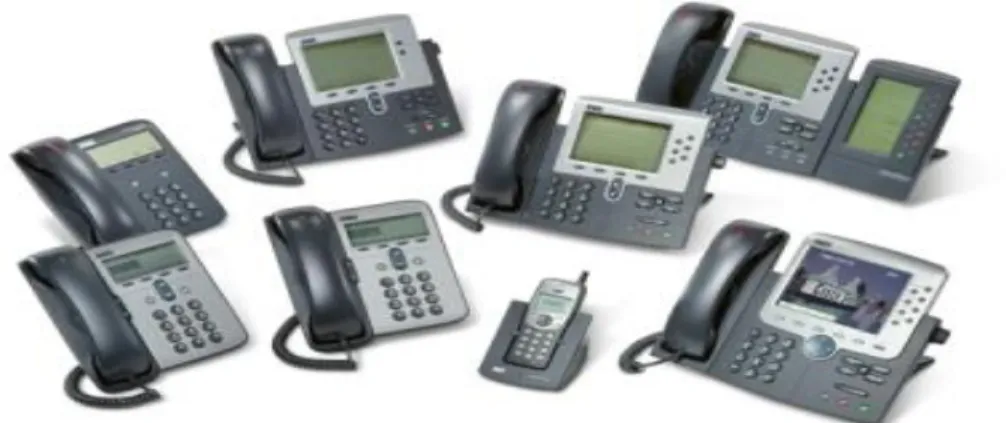
2.7.3 IP Phones ... 58
2.7.4 Analog Telephone Adapters ... 58
2.7.5 Interface Cards ... 59
2.8 CONNECTING TO THE PSTN ... 60
2.9 CONFIGURING THE IPNETWORK ... 60
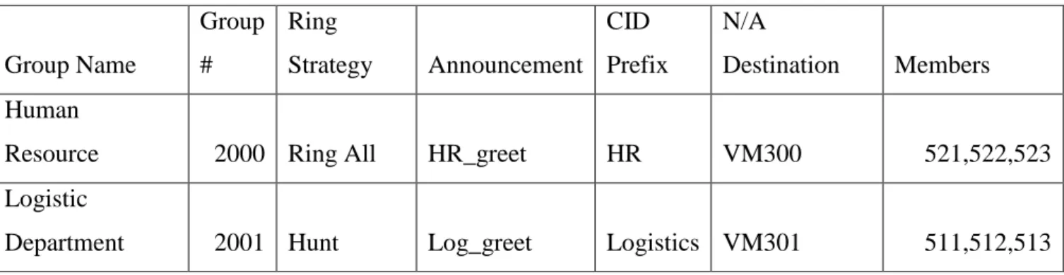
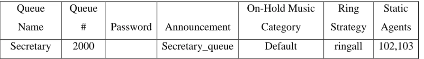
2.10 PBXIMPLEMENTATION ... 61 2.11 THE PLAN ... 61 2.11.1 Extensions ... 62 2.11.2 Number of Employees ... 62 2.11.3 Departmental Considerations ... 63 2.11.4 Ring Groups ... 65 2.11.5 Call Queues ... 66
ASTERISK INSTALLATION AND CONFIGURATION ... 67
3.1 INTRODUCTION ... 67
3.2 INSTALLING ASTERISK ... 67
3.3 ASTERISK CONFIGURATION ... 71
3.3.1 Asterisk config sip.conf ... 71
1. GENERAL SECTION ... 72 2. CLIENTS SECTION ... 73 3.3.2 User configuration ... 73 3.3.3 DIAL PLAN ... 75 1. EXTENSIONS ... 76 2. PRIORITIES ... 76 3. APPLICATIONS ... 76 4. CONTEXTS ... 77 CONCLUSION ... 79 BIBLIOGRAPHY ... 80
Page 7
Table 1-0-1 Table response messages ... 26
Table 1-0-2 Common SDP Extensions ... 31
Table 1-0-3 SDP field names ... 36
Table 2-0-1 Design Example of Ring Group ... 65
Page 8
Figure 0-1 Traditional PBX ... 14
Figure 0-2 Hybrid PBX ... 15
Figure 1-3 IAX complete call flow ... 21
Figure 1-4 IAX Call monitoring ... 22
Figure 1-5 the SIP message exchange between two SIP-enabled devices... 33
Figure 0-1 Asterisk PBX system... 50
Figure 0-2 Asterisk Architecture ... 51
Figure 0-3 Soft phone ... 57
Figure 0-4 IP Phone ... 58
Figure 0-5 Example of ATA ... 59
Figure 0-6 ATA 08 Analogue ports interface ... 59
Page 9 ACD: Automatic Call Distributor is a feature used to route calls in a call center environment to the
appropriate person based on factors such as availability, call usage, time, etc.
Agent: Member of a queue. AGI: Asterisk Gateway Interface.
ATA: Analog Telephone Adapter, a device used to connect an analog phone to a digital line. CDR: Call Detail Record. This is the log of a call.
Codec: A Codec is a piece of code that encodes or decodes audio using a given type of algorithm. CRM: Customer Relationship Management.
DID: Direct Inward Dialing simply refers to the phone number dialled by a caller to reach our
telephone system.
DISA: Direct Inward System Access.
Firewall: A device that exists at the border of two or more networks or network segments, and applies
policies to the traffic that traverses those borders based on the security requirements of the network.
Follow-Me: This feature of TrixBox uses ring groups to allow a user to float between multiple
extensions.
FXO: The Foreign eXchange Office is the end point of a connection. It is the FXO device that receives a
call.
FXS: A Foreign eXchange Station is the sender of the call to an end-point device.
IAX: Inter-Asterisk eXchange protocol. The protocol is developed by Digium as a simpler and
easier-to-manage alternative to using SIP for VoIP.
ISDN: Integrated Services Digital Network. This gained some popularity within small to
medium-sized businesses as a cost-effective way of connecting to the PSTN and getting some advanced services, like many lines to one office or voice and data lines on one service. ISDN is a digital service and offers a few more features over POTS.
ITSP: An Internet Telephone Service Provider can deliver telephone network connectivity to our
Asterisk PBX over Internet rather than over analog phone lines that need to be physically installed at our location.
IVR: Interactive Voice Response is known in the TrixBox system as the Digital Receptionist. This is the
system that creates voice-prompt menus to help callers locate the appropriate person to speak to.
Hard phone: This is a hardware-based telephone. Overhead Paging: Public Announcement System.
PBX: PBX (Private Branch eXchange) refers to the telephone switching system installed in a private
Page 10 POTS: Plain Old Telephone Service. This is commonly used for residential purposes. POTS is an
analog system and is controlled by electrical loops. It is provided by copper wires run to residences and places of business and is therefore the cheapest and easiest telephone service to roll out.
Predictive Dialer: Predictive Dialer is a software that dials ahead of a user in order to determine if the
dialled number is answered by a human rather than by a fax machine or is ringing out. It is used in call centers to increase productivity.
PSTN: Public Switched Telephone Network refers to the public phone network that carries all
traditional phone calls.
Queues: A call queue is a function that places callers into a waiting room while they wait for the next
available agent.
Ring Groups: A ring group is a collection of extensions that will all ring at the same time when a call
is transferred to the group's extension number.
SIP: Session Initiation Protocol. This is a commonly used VoIP protocol. SoftPhone: This is a software-based telephone.
Trunk: A trunk is a channel that operates between two distinct points. This can be either between
PBXs within an organization, or between the organization's PBX and its provider.
T1/E1: This is common in larger companies, although in recent years it has become more affordable.
T1/E1 is a digital service and offers yet more features than ISDN, the most important feature being increased bandwidth that translates, in telephony, to more telephone lines.
VoIP: The term VoIP simply means the ability to send voice communication over existing network
wires using the same methods that are used for other internet services such as email, web surfing, or instant messaging.
Page 11
Introduction
A PBX is an acronym for a Private Branch eXchange, which provides the internal telephone system. Telephone exchanges were initially under the control of the telephone providers, such as AT&T in the US or PTT in Algeria. These companies handled all line provisioning and call routing between the businesses and the public. Initially, the routing of calls was done by a team of operators sitting in the offices of the telephone companies and routing calls by plugging and unplugging cables to connect one caller to another. Eventually, as the reliance and the demands of this service grew, technology evolved to the point where we had automatic systems managing these calls.
As the modern telephone networks began to take shape, private companies saw a greater reliance on telephone communication. Many decided to implement their own services so that they could handle calls internal to the organization. Usually, the equipment was leased or bought from the telephone companies mentioned previously, so they were quite happy to help with these services. These companies also got to charge for the lines and calls connecting the company externally, and so they could profit from this too. So the expensive digital lines were now being used only as a means of communicating outside the building, rather than using externally provided lines for all communication.
At this point, it became obvious that there was a need for these companies to install their own telephone equipment to route internal calls and, in some cases, to make sure calls going out or coming into the company went via the correct routes. For example, you don't want Alice in accounting calling Bob in HR through a line that leaves the company and crosses continents if they sit within the same building. Therefore, there is a requirement for a PBX to effectively manage calls and ensure that they go via the most cost effective and reliable routes in order to keep the company communicating internally between departments and employees, and externally with customers and suppliers.
Page 12 In its basic form, a PBX is the interface between the public telephone network and the private network within the company. Since most companies need fewer phones lines than the number of employees they have, they can get away by having a few outgoing lines but many internal extensions so that employees can converse internally. This costs little more than the maintenance of the PBX and internal cabling, and there are no line rentals or other call charges being paid to the telecommunications provider. The PBX then handles all of the routing in and out of the company using the lines effectively. The PBX also handles calls within the company so that a call from one internal phone to another does not have to go out onto the phone circuits and back in.
As PBXs became more common, businesses and their employees required more features and functionality such as voicemail, call parking, call transfers, music on-hold, IVR menus, least-cost routing, and an Automatic Call Distributor (ACD) in order to provide for calling groups. With the increase in demand for communications in all aspects of a business, the features required in a phone system become more complex and more expensive. If modern companies had to rely on the telecommunications provider for all these features, the cost of communication could become prohibitively high.
In this thesis we will design and implement a PBX system based on Asterisk software, the first chapter will present some theoretical background that will help the reader understand the technology used in this PBX like VoIP and the different protocols used for transporting the voice data. In the second chapter will deal with practical aspect of the PBX like installation and configuration of ASTERISK and its different features, and we will end this thesis by a general conclusion that we will try to make some recommendations for future students that wish to continuo this modest work.
Page 13
Chapter One Voice over IP
1.1 Introduction
before we go through the technical aspect of the VoIP let us first check some definitions and introduce the PBX from a historical aspect and a technical one. so we will go in this chapter through the protocols used for call control like (SIP, IAX ) and others for voice data transport like RTP.
1.2 The Traditional PBX System
It is not hard to spot a traditional PBX system. It is usually a large box full of mechanical switches and relays mounted on a wall in 'the phone room'. When a company's requirement changes, they generally contact their PBX provider who will charge varying rates to make hardware and configuration changes to fit the new requirements. With PBXs being very complicated and each differing from the others greatly, it can take a considerable level of training and experience to provide the support for a busy PBX system. This leads to most PBX customers relying on their PBX suppliers for, often expensive, support. So while by bringing the communications internally businesses could benefit from savings on line rentals, they still often had a reliance on their providers for support. Often, the companies selling and supporting the PBXs were the same telecommunication companies providing the external lines.
With a traditional PBX system we would also almost always purchase our phone system from the same manufacturer as the PBX system, usually with very few options to choose from when it comes to contract options and hardware such as telephone handsets or headsets. Adding features like voicemail can usually be an expensive add-on to the base system, sometimes requiring an entirely new piece of equipment! A traditional PBX system has the following structure:
Page 14 Although some legacy PBX systems now have options for network access and VoIP functionality, these options are often very expensive upgrades and they generally lack the features and configuration options in the newer VoIP systems.
1.3 Hybrid PBX System
A hybrid PBX system combines the features of a traditional PBX system with VoIP functionality. In some cases, the VoIP functionality may just be the way the PBX communicates with the phones. Some other VoIP functionalities may include the ability to have remote extensions or Soft Phones, and the ability to use Internet Telephone Service Providers (ITSPs) and not just the traditional public telephone network. The main added benefit is the combined functionality, as we can keep all our existing lines and numbers and add in VoIP for substantial savings where possible.
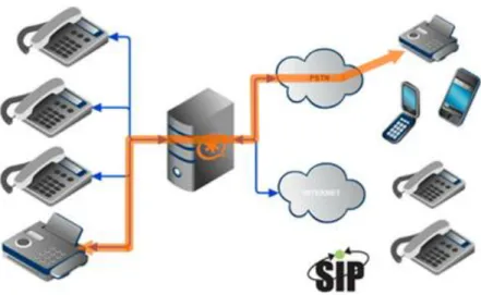
The Asterisk PBX system is a full hybrid system combining numerous types of connections to the public telephone network as well as VoIP functionality including:
Use of industry-standard SIP-compliant phones
Remote extensions using either SIP-compliant phones, or Soft Phones
Support for IAX (Inter-Asterisk eXchange)
Bridging remote Asterisk systems together to act as a single system Following is an example of a hybrid PBX system:
Page 15
Figure 0-2 Hybrid PBX 1.4 Voice over Internet protocol (VoIP)
We have covered, in brief, how a traditional PBX system could lack some of the features of a Voice over Internet Protocol system. We can now take a look at VoIP in a little bit more detail to get an idea of what the benefits are.
Firstly, it's important to realize that VoIP doesn't entirely replace the PSTN (although it could). VoIP is yet another, cheaper, and easier way to connect to the PSTN. You can make and receive calls that are initiated and terminated entirely across VoIP and you can call a standard PSTN number from VoIP and vice-versa, as long as your ITSP (Internet Telephony Service Provider) supports it or if you link your VoIP system to the PSTN yourself. Both of these are options to consider with the PBX.
A VoIP system can use a variety of protocols and we will cover some of those protocols relevant to our situation as we come across them. VoIP is a catch-all term for these protocols and refers to transferring voice data over the Internet.
As the Internet grew and became a more flexible system than the PSTN, it became apparent that it was possible and, in many cases, preferable to use the Internet for carrying voice as
Page 16 well as data. There were a few limitations that had to be overcome before this could be feasible. For example, data connections can tolerate some latency in communication but latency in voice can be very annoying as it leads to gaps in conversation and constant repetition. As Internet connection latency decreased and speeds increased, voice communication has become more viable. There is a tendency to think of VoIP as a new technology. However, it is almost two decades old and has only recently become so popular because there are now a few good pieces of software that use this technology. There are also many companies investing in VoIP, since the data lines that provide Internet services are now at a level where they are usually reliable enough to be used for voice communication. Customers and employees expect these data lines to be low-latency, clear, and always available. While many Internet services still have problems, the situation is certainly much better than it was in the late 80s and early 90s when VoIP was first touted as the killer technology. It wasn't quite there then, but is certainly getting there now.
The most important facet of VoIP is that it is "over Internet Protocol". This means that it benefits from the layered design of Internet communication and can be a very flexible communication mechanism. A VoIP implementation can generally be shifted from one service provider to another with little or no effect on the systems in use. Anyone that has gone through the nightmare of moving just a single telephone number between providers will realize the benefit VoIP brings in this area. Flexibility in communication is an important aspect for businesses as it helps to control the business process. VoIP is also many times cheaper than traditional telephone services as it can be routed over a variety of cheap lines. The most important aspect here is usually the long distance rates. Calls can traverse the Internet until they get to the same country, state, or city as the recipient before touching the PSTN and in some cases bypass the PSTN entirely, meaning that we are no longer shackled to our telecommunications provider. We can pick and choose from the many Internet Providers and/or Internet Telephone Service Providers. The one downside to VoIP is that Internet connections are often less stable than the PSTN and therefore we can have occasional downtime in our telephony service. This can be mitigated by having multiple providers with failover, something which is near to impossible or prohibitively expensive with a PSTN service.
Page 17
1.5 Signaling Transport
as we know that in order a call to be established we need some message interchange inorder that the call will be setup. in this chapter we will go through the different signaling protocols theory that are used in the PBX. and in the next chapter we will see the media transport and the different type of mechanisms that are used to establish a call.
1.5.1 H.323
A related Internet communications protocol is the ITU recommendation H.323, entitled “Packet-BasedMultimediaCommunication.”H.323isintroducedasarelated protocol to SIP for signaling VoIP and multimedia communication.
1.5.2 Introduction to H.323
H.323 is an umbrella recommendation that covers all aspects of multimedia communication over packet networks. It is part of the H.32x series of protocols that describes multimedia communication over ISDN, broadband (ATM), telephone (PSTN), and packet (IP) networks. Originally developed for video conferencing over a single LAN segment, the protocol has been extended to cover the general problem of telephony over the Internet. The first version was approved by the ITU in 1996 and was adopted by early IP telephony networks. Version 2 was adopted in 1998 to fix some of the problems and limitations in version 1. Version 3 was adopted in 1999 and includes modifications and extensions to enable communications over a larger network. Version 4 was adopted in 2000 with some major changes to the protocol. Versions 5 and 6 made very small changes to the protocol.
1.5.3 H.323 Entities
Let's start by explaining the names that H.323 uses for various entities that appear in the VoIP network.
A Terminal is typically a software or hardware VoIP phone. Certain programs (for
example, a voice mail software) could also introduce themselves as terminals in the protocol exchange.
Page 18
A Gateway is a device that allows a bidirectional communication with devices in another telecommunication network. The other network is usually PSTN but you can also have a H.323-to-SIP gateway or even a H.323-to-H.323 gateway. Formally, a gateway consists of two sub-components:
(1) Media Gateway Controller (MGC) handles call signaling and (2) Media Gateway (MG) routes the audio (and possibly video) streams.
You will usually find the two components implemented within a single box but they can also be separate if you want the gateway to scale to a higher number of concurrent calls (in that situation, you typically have a single MGC and several MGs).
A Multipoint Conference Unit (MCU) is a device that is used for multiparty conferencing. Again, it formally consists of two function blocks, a Multipoint Controller (MC) and Multipoint Processor (MP) where the latter is responsible for mixing the audio/video channels for the conference.
Terminals, gateways, and MCUs are collectively referred to as Endpoints. In addition to endpoints, the H.323 network can optionally have a fourth component, a Gatekeeper. Gatekeepers play the role of central controllers in the network. The most important tasks of a gatekeeper are registration of endpoints and call admission. The set of endpoints managed by the same gatekeeper is called a Zone.
1.5.4 Communication Between Entities
Let's now look how the individual entities that in the H.323 network use the various sub-protocols of H.323. First, for the endpoint-gatekeeper and gatekeeper-gatekeeper communication, a subset of the H.225.0 protocol is used. This subset of H.225.0 is known as RAS (Registration, Admission, Status). H.225.0-RAS contains messages for endpoint registration and unregistration at the gatekeeper, messages for call admission, call end, gatekeeper discovery, etc. The H.225.0-RAS messages are sent over the UDP protocol and the gatekeeper listens at port 1719/udp (unicast) and 1718/udp (multicast). The multicast address reserved for gatekeeper communication is 224.0.1.41. For call signaling between endpoints, H.323 uses the protocol Q.931. Q.931 has been borrowed from ISDN and it's messages contain the typical telephony data (like calling and called number).
Page 19 However, Q.931 does not have certain data fields that are needed for Voice over IP communication (for example IP addresses and listening ports). To solve this, Q.931 messages embed H.225.0 messages that carry the complete information. The H.225.0 message is encoded using ASN.1 PER to a binary form and then inserted into the corresponding Q.931 message to a field that can carry a custom string of bytes (known as the User-User Information Element). Generally speaking, the embedding of messages of one protocol inside the messages of another protocol is used quite frequently throughout H.323.
Third, the H.245 protocol is used to negotiate audio (and video) parameters between endpoints. The negotiation covers codecs, IP addresses and ports, i.e. the parameters needed for RTP streams. Last but not least, the Real Time Protocol (RTP) is used to carry the audio/video streams between the communicating endpoints.
1.6 IAX(The“Inter-AsteriskeXchange”Protocol)
IAX PROTOCOLIAX is an application layer protocol used for controlling and managing multimedia sessions over an IP network. It was created by open source community of branch exchange and its primary target was to efficiently control only voice calls over internet, but it is also capable of holding video streams with it. Mark Spencer Asterisk developed this protocol with the vision to decrease the complexity and to reduce the deficiencies of VOIP communication. IAX is an "all in one" protocol because of its ability to transmit media and control sessions together within same protocol. Unlike SIP or H.323 it does not require the support of RTP protocol. It uses single UDP stream to transmit and receive both signaling and media over static internal port number '4569'. Using single UDP static port IAX can bypass easily through firewalls and no other protocols are required to enable NAT with it. There is no requirement of extra configurations in the core network using IAX protocol to pass Nat Firewalls. It uses less overheads than RTP protocol and requires less bandwidth. IAX uses only 20% overhead with 4 bytes over a packet while RTP uses 60% of overheads with 12 bytes on each voice packet. IAX also has an ability of multiplexing and tunneling multiple channels over a single link. Data from multiple multimedia sessions are merged into single packet, thus reducing the IP overheads and reduce latency. By using G.729 compression codec multiple calls can be sent over single MB bandwidth. This protocol supports native encryption using different scenarios like AES-128 method. Unlike text commands in SIP, IAX uses binary data which
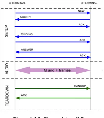
Page 20 is easily understandable by most of machines. All the signaling information is transferred only over data link layer. DTMF(duel tone mode frequency) tones are also send along with signaling information. Like SIP, IAX also has a mechanism of call flow. In IAX enabled communication, call creation and termination messages are exchanged directly among users, there is no involvement of server between them. When a new user enters in a network, it gets registered with the server and the users are connected with each other in the form of Peer-to-Peer connectivity. Let us take the example of call flow between user A and user B. When user A wants to communicate with user B, it dials its number and a 'New' message is send to user B along with DTMF tone. User B receives this message and respond with 'Accept' message. User A reply with an 'ACK'. When the device of user B starts ringing it sends 'Ring' message to user A and gets the 'ACK' in response from user A. After receiving the call user B tells the user A by 'Answer' message and in reply gets an 'ACK'. During conversation multimedia frames are exchanged among users. To terminate the call one user sends 'Hang-up' message to other user and after receiving 'ACK' session the line gets cleared.
Page 21 To check the peers during calls and after the call, IAX has the mechanism to exchange keep alive messages among the peers. During the call session one user sends a 'Ping' message to other user in order to check its availability and user which receives the ping message respond with 'Pong' message to ensure that, I am alive. When there is no call session running, peers send 'Poke' messages to their neighbors and respond with 'Pong' message. These messages also maintains the quality of service, by comparing the values of 'Jitter' and 'Dropped frames' enclosed in initial Ping/Poke frames with the Poke frames which are send in response. A flow of call monitoring messages is shown in Fig. 1-3
Page 22
Figure 1-4 IAX Call monitoring 1.7 SIP – Overview
SIP is a signaling protocol used to create, modify, and terminate a multimedia session over the Internet Protocol. A session is nothing but a simple call between two endpoints. An endpoint can be a smart phone, a laptop, or any device that can receive and transmit multimedia content over the Internet. SIP is incorporated with two widely used internet protocols: HTTP and SMTP. From HTTP, SIP borrowed the client-server architecture and the use of URL and URI. From SMTP, it borrowed a text encoding scheme and a header style. also SIP takes the help of SDP (Session Description Protocol) which describes a session and RTP (Real Time Transport Protocol) used for delivering voice and video over IP network. we will introduce the different elements related to the SIP protocol.
1.7.1 SIP URI
SIP entities are identified using SIP URI (Uniform Resource Identifier). A SIP URI has form of sip:username@domain, for instance, sip:[email protected]. As we can see, SIP URI consists of username part and domain name part delimited by @ (at) character. SIP URIs are similar to e-mail addresses, it is, for instance, possible to use the same URI for e-mail and SIP communication, such URIs are easy to remember.
Page 23
1.7.2
SIP Network Elements
Although in the simplest configuration it is possible to use just two user agents that send SIP messages directly to each other, a typical SIP network will contain more than one type of SIP elements. Basic SIP elements are user agents, proxies, registrars, and redirect servers. We will briefly describe them in this section.
Note that the elements, as presented in this section, are often only logical entities. It is often profitable to co-locate them together, for instance, to increase the speed of processing, but that depends on a particular implementation and configuration.
1. Client (user Agent)
Internet end points that use SIP to find each other and to negotiate a session characteristics are called user agents. User agents usually, but not necessarily, reside on a user's computer in form of an application--this is currently the most widely used approach, but user agents can be also cellular phones, PSTN gateways, PDAs, automated IVR systems and so on.
User agents are often referred to as User Agent Server (UAS) and User Agent Client (UAC). UAS and UAC are logical entities only, each user agent contains a UAC and UAS. UAC is the part of the user agent that sends requests and receives responses. UAS is the part of the user agent that receives requests and sends responses.
Because a user agent contains both UAC and UAS, we often say that a user agent behaves like a UAC or UAS. For instance, caller's user agent behaves like UAC when it sends an INVITE requests and receives responses to the request. Callee's user agent behaves like a UAS when it receives the INVITE and sends responses.
2. Servers
Servers are in general part of the network. They possess a predefined set of rules to handle the requests sent by clients. Servers can be of several types :
Proxy Server: These are the most common type of server in a SIP environment. When a request is generated, the exact address of the recipient is not known in advance. So the
Page 24 client sends the request to a proxy server. The server on behalf of the client (as if giving a proxy for it) forwards the request to another proxy server or the recipient itself.
Redirect Server: A redirect server redirects the request back to the client indicating that the client needs to try a different route to get to the recipient. It generally happens when a recipient has moved from its original position either temporarily or permanently.
Registrar Server: The registrar is a special SIP entity that receives registrations from users, extracts information about their current location (IP address, port and username in this case) and stores the information into location database.
Location Server: The addresses registered to a Registrar are stored in a Location Server.
1.7.3 SIP - Messaging
Communication using SIP (signaling) implicate the interchange of series of messages. Messages are transported independently by the network. Usually they are transported in a separate UDP datagram each. Each message consist of "first line", message header, and message body. The first line identifies the type of the message. There are two type of the messages: requests(often called method) and responses. Requests are usually used to initiate some action or inform the recipient of requesting something. Replies are used to confirm that a request was received and processed and contain the status of the processing.
1. -SIP Requests (methods):
SIP requests or methods are considered “verbs” in the protocol, since they request a specific action to be taken by another user agent or server. in SIP protocol there exist six original methods: The INVITE, REGISTER, BYE, ACK, CANCEL, and OPTIONS. And the NOTIFY, PUBLISH, REFER, MESSAGE, INFO, PRACK, UPDATE, SUBSCRIBE methods are described in separate RFCs.
INVITE :Invites a user to a call
ACK : Acknowledgement is used to facilitate reliable message exchange for INVITEs.
BYE :Terminates a connection between users
CANCEL :Terminates a request, or search, for a user. It is used if a client sends an INVITE and then changes its decision to call the recipient.
Page 25
OPTIONS :Solicits information about a server's capabilities.
REGISTER :Registers a user's current location
NOTIFY is used by a user agent to convey information about the occurrence of a particular event.
PUBLISH: is used by a user agent to send (or publish) event state information to a server known as an event state compositor
REFER : is used by a user agent to request another user agent to access a URI or URL resource.
MESSAGE : is used to transport instant messages (IM) using SIP.IMs usually consists of short messages exchanged in near-real time by participants engaged in a text conversation
INFO: is used by a UA to send call signaling information to another UA with which it has an established media session. The request is end-to-end and is never initiated by proxies
PRACK: is used to acknowledge receipt of reliably transported provisional responses.
UPDATE: is used to modify the state of a session without changing the state of the dialog.
SUBSCRIBE: is used by a UA to establish a subscription for the purpose of receiving notifications (via the NOTIFY method) about a particular event. A successful subscription establishes a dialog between the UAC and the UAS.
2. SIP Responses:
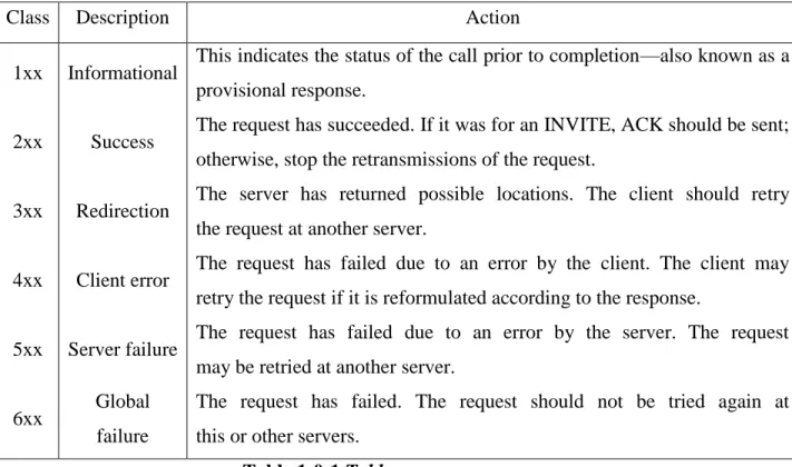
A SIP response is a message generated by a UAS or a SIP server to reply a request generated by a UAC. There are six classes of SIP responses. The first five classes were borrowed from HTTP; the sixth was created for SIP. as shown in the next table
Page 26
Class Description Action 1xx Informational This indicates the status of the call prior to completion—also known as a
provisional response.
2xx Success The request has succeeded. If it was for an INVITE, ACK should be sent; otherwise, stop the retransmissions of the request.
3xx Redirection The server has returned possible locations. The client should retry
the request at another server. 4xx Client error The request has failed due to an error by the client. The client may
retry the request if it is reformulated according to the response.
5xx Server failure The request has failed due to an error by the server. The request may be retried at another server.
6xx Global failure
The request has failed. The request should not be tried again at this or other servers.
Table 1-0-1 Table response messages 1.8 Session Description Protocol (SDP)
1.8.1 Introduction
One of the most important uses of SIP is to negotiate the setup of sessions, as the name suggests. To do this, SIP uses another protocol, Session Description Protocol, to describe the actual parameters of the media session. This includes information such as media type, codec, bit rate, and the IP address and port
numbers for the media session. In short, negotiating media sessions is all about exchanging the data necessary to begin the RTP media sessions or SRTP media sessions that will be described later. So let us have some description of this protocol.
1.8.2 Session Description Protocol :
SDP stands for Session Description Protocol. It is used to describe multimedia sessions in a format understood by the participants over a network. Depending on this description, a party decides whether to join a conference or when or how to join a conference.
Page 27
The owner of a conference advertises it over the network by sending multicast messages which contain description of the session e.g. the name of the owner, the name of the session, the coding, the timing etc. Depending on these information the recipients of the advertisement take a decision about participation in the session.
SDP is generally contained in the body part of Session Initiation Protocol (SIP).
SDP is defined in RFC 2327. An SDP message is composed of a series of lines, called fields, whose names are abbreviated by a single lower-case letter, and are in a required order to simplify parsing
1.8.3 Purpose of SDP
The purpose of SDP is to convey information about media streams in multimedia sessions to help participants join or gather info of a particular session.
SDP is a short structured textual description.
It conveys the name and purpose of the session, the media, protocols, codec formats, timing and transport information.
A tentative participant checks these information and decides whether to join a session and how and when to join a session if it decides to do so.
The format has entries in the form of <type> = <value>, where the <type> defines a unique session parameter and the <value> provides a specific value for that parameter.
The general form of a SDP message is: x = parameter1 parameter2 ... parameterN
The line begins with a single lower-case letter, for example, x. There are never any spaces between the letter and the =, and there is exactly one space between each parameter. Each field has a defined number of parameters.
1.8.4 Session Description Parameters
Session description (* denotes optional)
v = (protocol version)
o = (owner/creator and session identifier)
s = (session name)
Page 28
u =* (URI of description)
e =* (email address)
p =* (phone number)
c =* (connection information - not required if included in all media)
b =* (bandwidth information)
z =* (time zone adjustments)
k =* (encryption key)
a =* (zero or more session attribute lines) Protocol Version
The v = field contains the SDP version number. Because the current version of SDP is 0, a valid SDP message will always begin with v = 0
1. Origin
The o = field contains information about the originator of the session and session identifiers. This field is used to uniquely identify the session.
The field contains: o=<username><session-id><version><network-type><address-type>
The username parameter containstheoriginator’sloginorhost.
The session-id parameter is a Network Time Protocol (NTP) timestamp or a random number used to ensure uniqueness.
The version is a numeric field that is increased for each change to the session, also recommended to be a NTP timestamp.
The network-type is always IN for Internet. The address-type parameter is either IP4 or IP6 for IPv4 or IPv6 address either in dotted decimal form or a fully qualified host name.
2. Session Name and Information
The s= field contains a name for the session. It can contain any nonzero number of characters. The optional i= field contains information about the session. It can contain any number of characters.
3. URI
The optional u= field contains a uniform resource indicator (URI) with more information about the session.
Page 29
4. E-Mail Address and Phone Number
The optional e= field contains an e-mail address of the host of the session. The optional p= field contains a phone number.
5. Connection Data
The c= field contains information about the media connection.
The field contains: c = <network-type><address-type><connection-address>
The network-type parameter is defined as IN for the Internet.
The address-type is defined as IP4 for IPv4 addresses and IP6 for IPv6 addresses.
The connection-address is the IP address or host that will be sending the media packets, which could be either multicast or unicast.
If multicast, the connection-address field contains: connection-address = base-multicast-address/ttl/number-of-addresses
where ttl is the time-to-live value, and number-of-addresses indicates how many contiguous multicast addresses are included starting with the base-multicast address.
6. Bandwidth
The optional b= field contains information about the bandwidth required. It is of the form: b = modifier:bandwidth−value
7. Time, Repeat Times, and Time Zones
Thet=fieldcontainsthestarttimeandstoptimeofthesession.t=start−timestop−time
The optional r= field contains information about the repeat times that can be specified in either in NTP or in days (d), hours (h), or minutes (m).
The optional z= field contains information about the time zone offsets. This field is used if are occurring session spans a change from daylight savings to standard time, or vice versa.
8. Media Announcements
The optional m= field contains information about the type of media session. The field contains: m = media porttransportformat−list
Page 30
The media parameter is either audio, video, text, application, message, image, or control. The port parameter contains the port number.
The transport parameter contains the transport protocol or the RTP profile used.
The format-list contains more information about the media. Usually, it contains media payload types defined in RTP audio video profiles.
9. Attributes
The optional a= field contains attributes of the preceding media session. This field can be used to
extend SDP to provide more information about the media. If not fully understood by a SDP user, the
attribute field can be ignored. There can be one or more attribute fields for each media payload type listed in the media field.
Attributes in SDP can be either
session level, or
media level.
Session level means that the attribute is listed before the first media line in the SDP. If this is the case, the attribute applies to all the media lines below it.
Media level means it is listed after a media line. In this case, the attribute only applies to this particular media stream.
SDP can include both session level and media level attributes. If the same attribute appears as both, the media level attribute overrides the session level attribute for that particular media stream. Note that the connection data field can also be either session level or media level.
10. SDP Extensions
There are a number of SDP extensions that have been defined. Common ones are summarized in the following table.
Page 31
Attribute Name
a=rtcp Port and IP address for RTCP [6]
a=mid Media session identifier and grouping of media streams
a=group
a=setup Connection-oriented media using as TCP transport
a=connection
a=key-mgt Key management for MIKEY
a=crypto Key management for SRTP
a=floorctrl
Binary Floor Control Protocol (BFCP) information
a=confid a=userid a=floorid
a=fingerprint Connection-oriented media using TLS [
a=label Media label
a=accept-types
Message Session Relay Protocol (MSRP) information a=accept-wrapped-types a=max-size a=path a=ice-pwd
Interactive connectivity establishment (ICE) a=ice-ufrag
a=ice-lite a=ice-mismatch a=ice-options
a=chatroom Chat room name for MSRP
Table 1-0-2 Common SDP Extensions
The a = setup and a = connection attributes are used for connection oriented media, such as TCP.
Page 32
The a=connection:new indicates that a new TCP connection needs to be opened and that this endpoint will do a passive open (the other endpoint will do the active open).
The a = fingerprint contains a fingerprint of the certificate to be exchanged during the TLS handshake.
The a = confide and a = userid attributes contain the conference ID and user ID of the user.
The a = floorid attributes indicate that floor 1 is associated with a = label:1, which is associated with the m = audio stream while floor 2 is associated with a = label:2, which is associated with the m = video stream.
1.9 A Simple Session Establishment Example
After we have seen the Signaling protocol. now we will show the basic message exchange between two SIP devices to establish and tear down a session. This example will be introduced using call flow diagrams between a called and calling party, along with the details of each message. Each arrow in the figures represents a SIP message, with the arrowhead indicating the direction of transmission. The red line in the figures indicates the media stream. In these examples, the media will be assumed to be RTP packets containing audio, but it could be another protocol. Details Media are covered in the next Chapter.
Page 33
Figure 1-5the SIP message exchange between two SIP-enabled devices.
The two devices could be SIP phones, phone clients running on a laptop or PC (known as
softclients), PDAs, or mobile phones. It is assumed that both devices are connected to an IP
network such as the Internet and know each other’sIPaddress.
The calling party, Tesla, begins the message exchange by sending a SIP I NVITE message to the called party, Marconi. The INVITE contains the details of the type of session or call that is requested. It could be a simple voice (audio) session, a multimedia session such as a videoconference, or a gaming session.
Page 34
Figure 1-6 INVITE SIP message
Since SIP is a text-encoded protocol, this is actually what the SIP messagewouldlooklike“onthe wire”as aUDPdatagram beingtransportedover,forexample,Ethernet. Thefields listedin the INVITE message are called header fields.
They have the form Header: Value CRLF. The first line of the request message, called the start line, lists the method, which is INVITE, the Request-URI, then the SIP version number (2.0), all separated by spaces. Each line of a SIP message is terminated by a CRLF (Carriage Return Line Feed). The Request-URI is a special form of SIP URI and indicates the resource to which the request is being sent, also known as the request target.
The first header field following the start line shown is a Via header field. Each SIP device that originates or forwards a SIP message stamps its own address in a Via header field, usually written as a host name that can be resolved into an IP address using a DNS query. The Via header field contains the SIP version number (2.0), a “/”, then UDP for UDP transport, a space, the hostname or address, a colon, then a port number (in this example the “well-known” SIP port number 5060). The branch parameter is a transaction identifier. Responses relating to this request can be correlated because they will contain this same transaction identifier.
the Max-Forwards field is initialized to some large integer and decremented by each SIP server, which receives and forwards the request, providing simple loop detection.
INVITE sip:[email protected] SIP/2.0
Via: SIP/2.0/UDP lab.high-voltage.org:5060;branch=z9hG4bKfw19b Max-Forwards: 70
To: G. Marconi <sip:[email protected]>
From: Nikola Tesla <sip:[email protected]>;tag=76341 Call-ID: j2qu348ek2328ws
CSeq: 1 INVITE
Subject: About That Power Outage... Contact: <sip:[email protected]> Content-Type: application/sdp
Content-Length: 158 v=0
o=Tesla 2890844526 2890844526 IN IP4 lab.high-voltage.org s=Phone Call
c=IN IP4 100.101.102.103 t=0 0
m=audio 49170 RTP/AVP 0 a=rtpmap:0 PCMU/8000
Page 35 The next header fields are the To and From header fields, which show the originator and destination of the SIP request. SIP requests are routed based on the Request-URI instead of the To URI. This is because the Request-URI can be changed and rewritten as a request is forwarded, while the To URI generally stays the same. When a name label is used, as in this example, the SIP URI is enclosed in brackets <>. The name label could be displayed during alerting, for example, but is not used by the protocol.
The Call-ID header field is an identifier used to keep track of a particular SIP session. The originator of the request creates a locally unique string. Some older implementations also add an “@” and its host name to the string. In addition to the Call-ID, each party in the session also contributes a random identifier, unique for each call. The initiator of the session that generates the establishing INVITE generates the unique Call-ID and From tag. In the response to the INVITE, the user agent answering the request will generate the To tag. The combination of the local tag (contained in the From header field), remote tag (contained in the To header field), and the Call-ID uniquely identifies the established session, known as a dialog. This dialog identifier is used by both parties to identify this call because there could be multiple calls set up between them. Subsequent requests within the established session will use this dialog identifier.
the CSeq header field, or command sequence. It contains a number, followed by the method name, INVITE in this case. This number is incremented for each new request sent. In this example, the command sequence number is initialized to 1, but it could start at another integer value.
The Via header fields plus the Max-Forwards, To, From, Call-ID, and CSeq header fields represent the minimum required header field set in any SIP request message. Other header fields can be included as optional additional information, or information needed for a specific request type.
A Contact header field is also required in this INVITE message, which contains the SIP URI of Tesla communication device, known as a user agent (UA); this URI can be used to route messages directly to Tesla.
The optional Subject header field is present in this example. It is not used by the protocol, but could be displayed during alerting to aid the called party in deciding whether to accept the call. The same sort of useful prioritization and screening commonly performed using the
Page 36 Subject and From header fields in an e-mail message is also possible with a SIP INVITE request.
The Content-Type and Content-Length header fields indicate that the message body is Session Description Protocol or SDP and contains 158 octets of data. A blank line separates the message body
from the header field list, which ends with the Content-Length header field. In this case, there are seven lines of SDP data describing the media attributes that the caller Tesla desires for the call. This media information is needed because SIP makes no assumptions about the type of media session to be established the caller must specify exactly what type of session (audio, video, gaming) that he wishes to establish. The SDP field names are listed in Table 3, but a quick review of the lines shows the basic information necessary to establish a session.
SDP Parameter Parameter Name
v=0 Version number
o=Tesla 2890844526 2890844526 IN IP4
lab.high-voltage.org Origin
s=Phone Call Call subject
c=IN IP4 100.101.102.103 Connection t=0 0 Time m=audio 49170 RTP/AVP 0 Media a=rtpmap:0 PCMU/8000 Attributes
Page 37
SIP/2.0 180 Ringing
Via: SIP/2.0/UDP lab.high-voltage.org:5060;branch=z9hG4bKfw19b ;received=100.101.102.103
To: G. Marconi <sip:[email protected]>;tag=a53e42 From: Nikola Tesla <sip:[email protected]>;tag=76341 Call-ID: j2qu348ek2328ws
CSeq: 1 INVITE
Contact: <sip:[email protected]> Content-length: 0
Table 3 includes the:
•ConnectionIPaddress(100.101.102.103); •Mediaformat (audio); •Portnumber(49170); •Mediatransportprotocol(RTP); •Mediaencoding(PCMμLaw); •Samplingrate(8,000Hz).
The next message in Figure X.X is a 180 Ringing message sent in response to the INVITE. This message indicates that the called party, Marconi, has received the INVITE and that alerting is taking place. The alerting could be ringing a phone, a flashing message on a screen, or any other method of attracting the attention of the called party, Marconi.
The 180 Ringing is an example of a SIP response message. Responses are numerical and are classified by the first digit of the number. A 180 response is an informational class response, identified by the first digit being a 1. Informational responses are used to convey noncritical information about the progress of the
call. The response code number in SIP alone determines the way the response is interpreted by the server or the user. The reason phrase, Ringing in this case, is suggested in the standard, but any text can be used to convey more information.
The 180 Ringing response has the following structure:
Figure 1-7 180RINGING SIP message
The message was created by copying many of the header fields from the INVITE message, including the Via, To, From, Call-ID, and CSeq, then adding a response start line containing the
Page 38
SIP/2.0 200 OK
Via: SIP/2.0/UDP lab.high-voltage.org:5060;branch=z9hG4bKfw19b ;received=100.101.102.103
To: G. Marconi <sip:[email protected]>;tag=a53e42 From: Nikola Tesla <sip:[email protected]>;tag=76341 Call-ID: j2qu348ek2328ws CSeq: 1 INVITE Contact: <sip:[email protected]> Content-Type: application/sdp Content-Length: 155 v=0
o=Marconi 2890844528 2890844528 IN IP4 tower.radio.org s=Phone Call
c=IN IP4 200.201.202.203 t=0 0
m=audio 60000 RTP/AVP 0 a=rtpmap:0 PCMU/8000
SIP version number, the response code, and the reason phrase. This approach simplifies the message processing for responses.
The Via header field contains the original branch parameter but also has an additional received parameter. This parameter contains the literal IP address that the request was received from (100.101.102.103), which typically is the same address that the URI in the Via resolves using DNS (lab.high-voltage.org). Note that the To and From header fields are not reversed in the response message as one might expect them to be. Even though this message is sent to Marconi from Tesla, the header fields read the opposite. This is because the To and From header fields in SIP are defined to indicate the direction of the request, not the direction of the message. Since Tesla initiated this request, all responses to this INVITE will read To: Marconi From: Tesla. The To header field now contains a tag that was generated by Marconi. All future requests and responses in this session or dialog will contain both the tag generated by Tesla and the tag generated by Marconi. The response also contains a Contact header field, which contains an address at which Marconi can be contacted directly once the session is established. When the called party, Marconi, decides to accept the call (i.e., the phone is answered), a 200 OK response is sent. This response also indicates that the type of media session proposed by the caller is acceptable. The 200 OK is an example of a success class response. The 200 OK message body contains Marconi’s media information:
Page 39
ACK sip:[email protected] SIP/2.0
Via: SIP/2.0/UDP lab.high-voltage.rg:5060;branch=z9hG4bK321g Max-Forwards: 70
To: G. Marconi <sip:[email protected]>;tag=a53e42 From: Nikola Tesla <sip:[email protected]>;tag=76341 Call-ID: j2qu348ek2328ws
CSeq: 1 ACK Content-Length: 0
This response is constructed the same way as the 180 Ringing response and contains the same To tag and Contact URI. The media capabilities, however, must be communicated in a SDP message body added to the response. the SDP contains:
•End-point IP address (200.201.202.203); •Mediaformat(audio); •Portnumber(60000); •Mediatransportprotocol(RTP); •Mediaencoding(PCMμ-Law); •Samplingrate(8,000Hz).
The final step is to confirm the media session with an acknowledgment request. The confirmation means that Tesla has successfully received Marconi’s response. This exchange of media information allows the media session to be established using another protocol: RTP in this example.
Figure 1-9 ACK SIP message
The command sequence, CSeq, has the same number as the INVITE, but the method is set to ACK. At this point, the media session begins using the media information carried in the SIP messages. The media session takes place using another protocol, typically RTP. The branch parameter in the Via header field contains a newer transaction identifier than the INVITE, since an ACK sent to acknowledge a 200 OK is considered a separate transaction. This message exchange shows that SIP is an end-to-end signaling protocol. A SIP network or SIP server is not required for the protocol to be used. Two end
pointsrunningaSIPprotocolstackandknowingeachother’sIPaddresses can use SIP to set up a media session between them. Although less obvious, this example also shows the client-server nature of the SIP protocol. When Tesla originates the INVITE request, he is acting as a SIP client. When Marconi responds
Page 40
SIP/2.0 200 OK
Via: SIP/2.0/UDP tower.radio.org:5060;branch=z9hG4bK392kf ;received=200.201.202.203
To: Nikola Tesla <sip:[email protected]>;tag=76341 From: G. Marconi <sip:[email protected]>;tag=a53e42 Call-ID: j2qu348ek2328ws
CSeq: 1392 BYE Content-Length: 0
to the request, he is acting as a SIP server. After the media session is established, Marconi originates the BYE request and acts as the SIP client, while Tesla acts as the SIP server when he responds. This is why a SIP-enabled device must contain both SIP user agent server and SIP user agent client software during a typical session, both are needed. This is quite different from other client-server Internet protocols such as HTTP or FTP. The Web browser is always an HTTP client, and the Web server is always an HTTP server, and similarly for FTP. In SIP, an end point will switch back and forth during a session between being a client and a server.
In Figure 2.1, a BYE request is sent by Marconi to terminate the media session:
The Via header field in this example is populatedwithMarconi’shostaddressandcontains a new transaction identifier since the BYE is considered a separate transaction from the INVITE or ACK transactions shown previously. The To and From header fields reflect that this request is originated by Marconi, as they
are reversed from the messages in the previous transaction. Tesla, however, is able to identify the dialog using the presence of the same local and remote tags and Call-ID as the INVITE, and tear down the correct media session. Notice that all of the branch IDs shown in the example so far begin with the string z9hG4bK. This is a special string that indicates that the branch ID has been calculated using strict rules defined in RFC 3261 and is as a result usable as a transaction identifier.
The confirmation response to the BYE is a 200 OK:
Figure 1-10 200 OK SIP message
The response echoes the CSeq of the original request: 1392 BYE. No ACK is sent since ACK is only sent in response to INVITE requests.
Page 41
1.10 Media Transport
Establishing media sessions is one of the most important applications of SIP in Internet communications. An understanding of the issues relating to media transport of voice, video, DTMF, and text helps motivate the media negotiation capabilities of SIP. In this chapter, the Real-Time Transport Protocol (RTP) will
be introduced as the protocol that transports actual media samples. The basic steps in audio media encoding and decoding are discussed. The RTP header format is covered along with common RTP topologies. The RTP Control Protocol (RTCP) is introduced as a way to monitor call quality. RTP profiles and common audio codecs are discussed.
1.10.1 Real-Time Transport Protocol (RTP)
Real-Time Transport Protocol was developed to enable the transport of real time datagrams containing voice, video, or other information over IP. RTP was not the first VoIP protocol used on the Internet. Network Voice Protocol (NVP) was implemented in 1973 to carry real-time voice communications over the Internet. Early versions of RTP, first implemented in 1992, were used to transportvoiceovertheInternet’smulticastbackbone(MBONE).BothH.323andSIPuseRTPfor media transport, making it the most common standard for Internet communications.
RTP is defined by the IETF proposed standard RFC 3550 (which updates the original RFC 1889). RTP does not provide any quality of service over the IP network, RTP packets are handled the same as all other packets in an IP network. However, RTP allows for the detection of some of the impairments introduced by an IP network, such as:
•Packetloss;
•Variabletransportdelay; •Outofsequencepacketarrival; •Asymmetricrouting.
Here is how RTP fits into the common media processing steps.