Jérôme Loicq
, Damien Baron
, Karl Fleury-Frenette
, Pascal Blain
, Alexandra Mazzoli
, Benoit
Hubert
b, Emma Spanswick
c, Greg Enno
c, Eric Donovan
caCentre Spatial de Liege, STAR institute, University of Liege, Belgium
bLPAP, Astrophysics and Geophysics Institute, STAR institute, University of Liege Belgium cDepartment of Physics and Astronomy, University of Calgary, Canada
Abstract
The Ultraviolet Imager (UVI) instrument is a very challenging imager developed in the frame of the SMILE-ESA mission. The instrument development is led by the University of Calgary. The UV camera will consist of a single imaging system targeted at a portion of the Lyman-Birge-Hopfield (LBH) N2 wavelength band. The baseline design of the imager meets the requirements to record snapshots of auroral dynamics with sufficient spatial resolution to measure cusp processes (100 km) under fully sunlit conditions from the specified apogee of the spacecraft. To achieve this goal, the UVI instrument utilizes a combination of four on-axis mirrors with an intensified FUV CMOS based camera. The mirrors will be coated with spectral selective interferometric layers to provide most of the signal filtering.
The objective of these filters is to select the scientific waveband between 160 and 180 nm. The combined four mirrors and detector have to give an out-of-band rejection ratio as low as possible to reject light from solar diffusion, dayglow and unwanted atomic lines in a range of 10-8 – 10-9. Different multilayer coatings are considered and optimized according to the π-multilayer equation for different H/L ratio and for different angles of incidence.
Our theoretical evaluation shows a modification of the reflectance spectrum as a function of the angle of incidence, hence the optical beams hitting the different mirrors can have different optical properties depending on the optical fields and the distribution of the rays on the pupil. We will evaluate the effect of fields on the spectral throughput of the UVI instrument based on its optical design. This analysis will be done using the Code V ray-trace software and proprietary Matlab scripts.
Keywords: Multi-layer coating, SMILE mission, Aurora
1.
INTRODUCTION
SMILE (Solar wind Magnetosphere Ionosphere Link Explorer) is a joint mission between ESA and the Chinese Academy of Sciences (CAS) with a planned launch date in November 2021. The mission aims at increasing our understanding of the connection between the interaction of the Solar wind with the Earth magnetosphere by looking at the nose and cusps of the magnetosphere and the aurorae at the North pole simultaneously while monitoring the in-situ plasma environment. In particular, SMILE will:
• Investigate the dynamic response of the Earth’s magnetosphere to the solar wind impact in a unique and global manner.
• Combine Solar Wind Charge exchange (SWCX) X-ray imaging of the dayside magnetos-heath and cusps with simultaneous UV imaging of the Earth’s northern aurora, while monitoring the solar wind conditions in situ.
• Investigate the full chain of events that drive Sun-Earth relationships: dayside reconnection / magnetospheric substorm cycle / CME-driven storms.
The baseline orbit satisfying the science requirements is a Highly Elliptical Orbit (HEO) around the Earth with an apogee of 121000 km and a perigee of 5000 km. The inclination of the orbit should be > 63 degrees and the argument of perigee is around 270 degrees. This orbit ensures a long time around apogee for observing the regions of interest with a relatively low perigee for downloading the scientific data without diving too deep into Earth’s radiation belts. Nominal science operation is planned for 3 years.
1.1 UVI instrument requirements and scientific goal
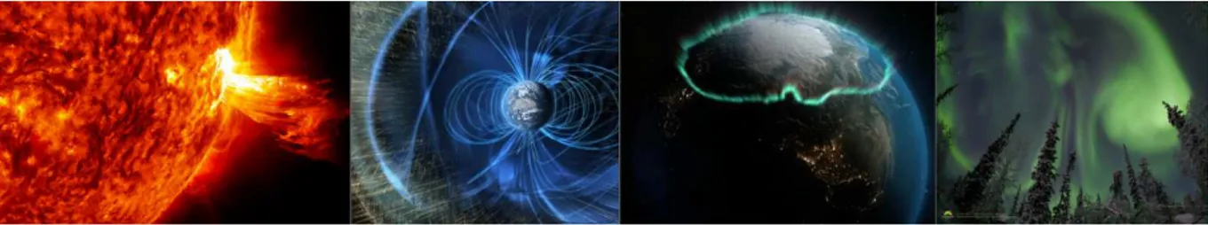
The scientific motivation for SMILE-UVI is to image the consequences of the solar wind-magnetosphere interaction and provide the most complete/highest resolution global images of the aurora ever taken. Data from SMILE-UVI will usher in a new era of geospace research. For the first time, researchers will track the causal chain of space weather through geospace, from the solar wind driver to its ultimate consequences in the radiation belts and ionosphere. Being the only global auroral imager during the mission timeframe, its data will be used for a multitude of reasons by researchers around the world.
Figure 1: The aurora is powered by the solar wind/magnetosphere interaction, produced by magnetospheric plasma processes, and affects the ionosphere and upper atmosphere.
As discussed extensively in Donovan et al. [1], after nearly four decades of auroral imaging from space the result has been images with spatial resolution typically around 100 km, with temporal resolution of 30 seconds to two minutes (or longer). The historically low SNR of UV imagers leaves low-light level emissions undetected, due in part to low suppression of out-of-band signal results in low daylight suppression. Although auroral imaging from space has been tremendously important in the evolution of geospace science, in a very real sense we have only just begun to capitalize on the richness of opportunities that auroral imaging from space has to offer (see Figure 2). We have only limited information about the auroral distribution of time and space scales and how that distribution evolves in time. Our understanding of how the spatial extent of aurora of different types (e.g., patchy, Alfvenic, etc.) evolves in response to changing geospace conditions is very limited and in most cases comes from the partial view afforded by ground-based instruments. It is mandatory to increase the knowledge on key parameters such as the open flux in the polar cap through long duration geomagnetic events such as Steady Magnetospheric Convection and magnetic storms, which is one of the main goal of the SMILE mission.
Figure 2: After nearly four decades of auroral imaging from space the result has been images such as those shown here (left) provided by the Canadian UV imager on the Swedish Viking satellite [2] and (right) the Canadian built UV “WIC” imager on
the NASA IMAGE satellite [3]. While UV imaging from space has been tremendously important to geospace science, improving the imaging quality especially in the dayside is very important.
For SMILE, the baseline requirements for the UV images of Earth’s aurora have been set at 150 km or better spatial resolution from locations on orbit greater than 19 RE geocentric. The further requirements on detection of the dayside cusp and the polar cap boundary (from apogees) drive the high level specifications listed below;
Table 1: High level SMILE-UVI specifications
Field of View 10 degrees
Spatial Resolution 150km @19Re
Temporal Resolution 60s
Spectral Band 160-180nm
Detection Threshold 100R @60s cadence, SNR greater than 1
Dynamic Range 30kR
To reach the spectral requirements of SMILE-UVI specific coatings are being developed. These filters are one of the key elements of the mission, directly coupled to the science objectives. These filters will be implemented as 4 reflective optical coatings made of thin film multilayers deposited on each mirror of the UVI. The objective of these filters is to select the scientific waveband between 160 and 180 nm. Out-of-band, the combined four mirrors have to give a rejection ratio as high as possible to reject light from solar diffusion, dayglow and unwanted atomic lines. The expected rejection ratio, all components combined (detector included) has to be in the range of 10-8 – 10-9.
2.
UVI INSTRUMENT CONCEPT
The UV camera will consist of a single imaging system targeted at a portion of the Lyman-Birge-Hopfield (LBH) N2 wavelength band (160-180nm). The UVI utilizes a four mirror on-axis system with an intensified FUV CMOS-based camera. The optical design is represented on Figure 3.
Figure 3: UV telescope optical design ray tracing. Light enters from the left and is reflected on four mirrors before focusing on the detector (far right).
The design calls for thin film filter coatings to be deposited on each of the imaging mirrors to provide the vast majority of the signal filtering. Further filtering is accomplished via the detector (photocathode, window, MCP, and CMOS sensor).
Preliminary system modeling shows that the combination of the four filtering surfaces, image intensifier and a CMOS sensor can readily accomplish the required out-of-band rejection required to image the aurora during sunlit conditions. The image-forming section of the camera comprises a fast, on-axis all-reflecting telescope with three spherical mirrors and one elliptical conical mirror (Figure 3). This type of reflecting telescope is very compact, and has excellent light gathering power. Moreover, it has excellent resolution over most of its FOV and has a high throughput in the far ultraviolet part of the spectrum. The camera has a FOV of 10°. The imager will operate in a self-filtering mode, utilizing thin film coatings on each of the four mirrors surfaces [4]. These filters, the topic of this paper, have very low reflectivity in the Visible and Near-UV region, and are specifically manufactured for high reflectivity in the LBH wavelength region, as required.
3.
COATING OPTICAL DESIGN
Compared to other UV-instruments where spectral selection is achieved with gratings [5-6], the challenge of the development of such instrument lies mainly on the performances of the coating deposition on the optical mirror surfaces. The -multilayer technology [7-8] seems to be the most promising technology to realize such challenge. -multilayer is defined as a periodic structure along the depth of the coating. They are composed of at least two materials with optical thicknesses called H and L. H is relative to a high-index film, while L is a low index material.
Three periodic multilayers have been considered so far: MgF2/LaF3, Al/MgF2 and Al/LaF3. The latter has been excluded from the analysis because a too large fraction of the incident light flux is lost by absorption inside the coating giving the throughput too low. Moreover, these multilayers have been chosen to satisfy π-multilayer equation [7,8]:
+ =
2,
where H, L and λr account respectively for the highest refractive index material optical thickness at λr and the lowest refractive index material optical thickness at λr and the reference wavelength,. For the following computations, we set down = 170nm. Of course, if the light angle of incidence changes, H and L have to change accordingly in order to satisfy this equation. Therefore, each multilayer has to be optimized for one specific angle of incidence.
Periodic thin film multilayer H-material L-material
MgF2/Al MgF2 Al
LaF3/MgF2 LaF3 MgF2
Theoretical analyses have been performed by using Transfer-matrix method [9] implemented on a homemade Matlab® code.
3.1 Thin film materials
This section presents the refractive index and extinction coefficient of each material involved in the coatings. They are depicted on Figure 4 to Figure 6. Due to a lack of information in the UV-visible range above 250 nm for LaF3, only Far-UV range is presented. However, a number of additional ellipsometry measurements in the Far-UV-visible range (from 190 nm to 800 nm) are foreseen in the near future to be performed at CSL to evaluate the filter performances in the visible.
Magnesium Fluoride
Figure 4: Optical constants of MgF2 from [10] (dots) and interpolated data (continuous line).
Lanthanum Fluoride
Aluminum (Al)
Figure 6: Optical constants of Al from [10] (dots) and interpolated data (continuous line).
3.2 Coating spectra optimized for normal incidence
Thin film multilayers have been optimized according to -multilayer equation for different H/L ratio and for different incidence angles. Reflectance spectra in the FUV region corresponding to multilayers optimized for normal incidence and specific values of H/L ratio are depicted below for each type of coatings.
MgF2/Al multilayer
LaF3/MgF2 multilayer
Figure 8: Reflectance spectrum for a [LaF3/MgF2]25 multilayer with H/L=0.3 at normal incidence.
3.3 Angular dependency for a given coating stack
One of the main concern of interference filters is their dependencies with the incidence angle. While speaking about wide field telescope, one can be worried by the wide range of ray angles hitting the optical surfaces. Coating angular sensitivity has then to be considered. Coatings are optimized for a specific angle, let say θ = 10° in the present simulations which corresponds to the average incidence angle on the first mirror. However, ray analysis shows that minimum and maximum incidence angles are quite different, ranging from θ = 5° to θ = 15° while keeping the same coating configuration, obviously. It turns out that coating performances are robust when the angle of incidence θ varies. There is no significant decrease of central wavelength throughput. The main effect is a wavelength shift of the spectral curve. In both coating types, the increase of the AOI blueshifts the curve maximum as shown on Figure 9.
4.
COATING ON THE OPTICAL DESIGN: EFFECT OF FIELDS AND ANGLES
As the theoretical evaluation shows a modification of the reflectance spectrum as a function of the angle of incidence, it is right to think that the optical beam hitting the different mirrors can have different optical properties with the optical fields and with the rays distributed on the instrument pupil. This section intends to evaluate the effect of fields on spectral throughput due to different angles of incidence associated to fields and rays hitting location on mirrors. Both coating types (MgF2/Al and LaF3/MgF2) have been evaluated.
4.1 Methodology
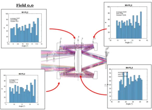
Based on the optical design of the UVI instrument, a first analysis of the angles of incidence distribution is performed for every field. This analysis is done with Code V. Along the rays and for each ray generated, a set of four angles of incidence (AOI) is calculated. These AOI will then be used to generate the spectral properties of the reflected beam through the optical telescope. The calculation is based on the fact that a ray contains all the spectral content and no wavelength dispersion occurs in the instrument. The spectral properties due to reflections along the rays are combined by multiplying the spectral response, while these responses are averaged over all the rays defining the fields and distributed over the entrance pupil. Results for central field is represented on Figure 10. Other fields have been analyzed. While central field has a symmetric profile around average angle because of on-axis instrument, off-axis fields present non-symmetric angle profile as depicted on Figure 11 and Figure 12.
Figure 10: Distribution of ray incidence angles reflected on the four UVI-mirrors. The represented field is the central one (0,0).
Figure 11: Angle distribution on the four UVI mirror for field (0,5).
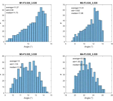
Figure 12: Angle distribution on the four UVI mirror for field (3.5,3.5). Angle (°) 5 10 15 # 0 10 20 30 40 50 60 70 average=11.27 std=2.08 median=11.73 M1-F3.535_3.535 Angle (°) 6 8 10 12 14 16 # 0 10 20 30 40 50 60 70 average=11.61 std=1.632 median=11.98 M2-F3.535_3.535 Angle (°) 9 10 11 12 13 14 15 # 0 10 20 30 40 50 60 average=12 std=1.118 median=11.98 M3-F3.535_3.535 Angle (°) 18 20 22 24 26 28 # 0 10 20 30 40 50 60 average=22.55 std=1.55 median=22.43 M4-F3.535_3.535
4.2 Throughput evaluation
Using the ray analysis preformed in the previous section and the coating performance evaluation tool presented in section 3, the throughput of each ray entering into the instrument can be evaluated. Ray throughput is averaged over the whole rays set entering through the instrument pupil. Each useful field is also analyzed. The following graphs (Figure 13 & Figure 14) present the spectral response of each individual reflection on the mirrors considering the specific angle of incidence associated to a specific ray. The dashed line corresponds to the equivalent filter response by all four mirrors and normalized to 1 mirror. Four specific rays are represented among a set of thousand rays.
Figure 13: [LaF3/MgF2] Spectral property of the individual reflection through the optical system. Four specific rays are represented among thousand. M1 to M4 reflectivity are represented for these specific rays. Dashed line corresponds to a
hypothetic filter including the effect of the four.
Figure 14 (left) represents the coatings response along all thousand rays after the four mirror reflections. The right-graph is the averaged responses on the (0,0)- field focal point. Results are presented in log-scale to highlight the depth of the coating reflectivity. On Figure 15 is represented the equivalent filter combining all the coating effects on the four mirrors. The same methodology has been applied on useful fields of view of the UVI-instrument. It is important to note that the filter response is quite similar for the three first mirror while the spectral reflectivity response of the fourth one is blueshifted. This effect is easily explained by the average angle of incidence which is approximately twice the angle of incidence of the three other mirrors. Figure 16 represents the spectral response for all fields.
Figure 14: [LaF3/MgF2] all rays represented after four reflections – Field 0,0
Figure 15: [LaF3/MgF2] Equivalent filter corresponding to the combination of the four mirrors contributions reduced to one mirror.
Figure 16: [LaF3/MgF2] Spectral throughput for all fields.
5.
CONCLUSION
The present article exposes the concept of spectral selectivity with the aim of the interference coating to be placed on the UVI mirrors surfaces. Presently, two generic designs were analyzed: [MgF2/Al] and [LaF3/MgF2]. Both filters are considered as interferential filters and they are designed with the -multilayer approach. These filters are then composed of a periodic stack assembly of two different materials (refractive index) and thicknesses. A period is based on the combination of both materials and their thickness. To converge to the best solution, the space of parameters (layers number, optical thicknesses ratio,…) has been explored. Interactions with the optical design have been calculated giving a simple conclusion: the spectral responses are quite similar over fields. The wide range of angles over the instrument does not modify significantly the spectral properties of the Instrument throughput.
6.
REFERENCES
[1] Donovan, E., Trondsen, T., Spann, J., Liu, W., Spanswick, E. et al (2007). Global auroral imaging in the ILWS era.
Advances in Space Research, 40(3), 409–418.
[2] Anger, C. D., Babey, S. K., Broadfoot, A. L., Brown, R. G., Cogger, L. L., Gattinger, R., … Jones, A. V. (1987). An ultraviolet auroral imager for the Viking spacecraft. Geophysical Research Letters, 14(4), 387–390.
[3] S. B. Mende, H. Heetderk, H. U.Frey, M. Lampton, S. P. Geller, R. Abiad,O. H.W.Siegmund, A. S.Tremsin, J.Spann, H. Dougani, S. A. Fuselier, A. L.Magoncelli, M.B. Bumala,S.Murphree And T. Trondsen, Far Ultraviolet Imaging From The Image Spacecraft . 2 . Wideband Fuv Imaging, Space Science Reviews 91: 271–285, 2000.
[4] Torr, M. R., Torr, D. G., Zukic, M., Johnson, R. B., Ajello, J., Banks, P, Spann, J. (1995). A far ultraviolet imager for the International Solar-Terrestrial Physics Mission. Space Science Reviews, 71(1–4), 329–383.
[6] Loicq, J., Kintziger, C., Mazzoli, A., Miller, T., Chou, C., Frey, H. U., … Mende, S. B. (2016). Optical design and optical properties of a VUV spectrographic imager for ICON mission. In Proceedings of SPIE - The International
Society for Optical Engineering (Vol. 9905).
[7] Zukic, M., & Torr, D. G. (1992). Multiple reflectors as narrow-band and broadband vacuum ultraviolet filters.
Applied Optics, 31(10), 1588.
[8] Wang, X. D., Chen, B., Wang, H. F., He, F., Zheng, X., He, L. P., Li, Y. P. (2015). Design and fabrication of far ultraviolet filters based on π-multilayer technology in high-k materials. Scientific Reports, 5, 1–6.
[9] M. Lequine and C. Amra. De l’Optique électromagnétique à l’Interférométrie. EDP Sciences (2013). ISBN : 978-2-7598-1022-2.

![Figure 4: Optical constants of MgF2 from [10] (dots) and interpolated data (continuous line)](https://thumb-eu.123doks.com/thumbv2/123doknet/6674176.182948/5.892.200.694.181.454/figure-optical-constants-mgf-dots-interpolated-data-continuous.webp)
![Figure 7: Reflectance spectrum for a [MgF 2 /Al] 25 multilayer with H/L=400 at normal incidence](https://thumb-eu.123doks.com/thumbv2/123doknet/6674176.182948/6.892.246.638.663.906/figure-reflectance-spectrum-mgf-al-multilayer-normal-incidence.webp)
![Figure 8: Reflectance spectrum for a [LaF 3 /MgF 2 ] 25 multilayer with H/L=0.3 at normal incidence](https://thumb-eu.123doks.com/thumbv2/123doknet/6674176.182948/7.892.253.632.193.458/figure-reflectance-spectrum-laf-mgf-multilayer-normal-incidence.webp)
![Figure 13: [LaF3/MgF2] Spectral property of the individual reflection through the optical system](https://thumb-eu.123doks.com/thumbv2/123doknet/6674176.182948/10.892.141.739.330.788/figure-laf-mgf-spectral-property-individual-reflection-optical.webp)
![Figure 14: [LaF3/MgF2] all rays represented after four reflections – Field 0,0](https://thumb-eu.123doks.com/thumbv2/123doknet/6674176.182948/11.892.125.789.177.457/figure-laf-mgf-rays-represented-reflections-field.webp)
![Figure 16: [LaF3/MgF2] Spectral throughput for all fields.](https://thumb-eu.123doks.com/thumbv2/123doknet/6674176.182948/12.892.295.598.168.405/figure-laf-mgf-spectral-throughput-fields.webp)
