HAL Id: hal-01008620
https://hal.archives-ouvertes.fr/hal-01008620
Submitted on 21 Oct 2018HAL is a multi-disciplinary open access archive for the deposit and dissemination of sci-entific research documents, whether they are pub-lished or not. The documents may come from
L’archive ouverte pluridisciplinaire HAL, est destinée au dépôt et à la diffusion de documents scientifiques de niveau recherche, publiés ou non, émanant des établissements d’enseignement et de
Optimal design of stiffened composite underwater hulls
Tanguy Messager, Pierre Chauchot, Benoit Bigourdan
To cite this version:
Tanguy Messager, Pierre Chauchot, Benoit Bigourdan. Optimal design of stiffened composite under-water hulls. 3rd European Conference on Computational Mechanics [ECCM-2006], 2006, Lisbonne, Portugal. �hal-01008620�
OPTIMAL DESIGN OF STIFFENED
COMPOSITE UNDERWATER HULLS
Tanguy Messager1, Pierre Chauchot2, Benoit Bigourdan21
Institut de recherche en Génie civil et Mécanique (GeM), UMR CNRS 6183 Ecole Centrale de Nantes, BP 92101, 44321 Nantes cédex3, France
2
Institut Français de Recherche pour l'Exploitation de la Mer (IFREMER) Service Matériaux et Structures, BP 70, 29280 Plouzané, France
{pierre.chauchot, benoit.bigourdan}@ifremer.fr
Keywords: Composite, Cylinders, Stiffeners, Buckling, Optimization.
Abstract. This numerical study deals with the stiffened composite underwater vessel design. The structures under investigation are laminated cylinders with rigid end-closures and inter-nal circumferential and longitudiinter-nal unidirectiointer-nal composite stiffeners. Structural buckling induced by the high external hydrostatic pressure is considered as the major failure risk. An optimization design tool has been developed to obtain the reinforcement definition which maximizes the limit of stability: an analytical model of cylindrical composite shell buckling has been coupled to a genetic algorithm procedure. The numerical optimization tests carried out corroborate design tendencies validated previously by experiments.
1 INTRODUCTION
Numerous works have focused last decade on the design of deep submarine exploration housings and autonomous underwater vehicles [1-4]. For submersible devices of limited en-ergy carrying capability, fiber reinforced composite materials enable low weight to displace-ment ratios and consequently enhance the endurance. The previous studies have shown that structural buckling induced by the high external hydrostatic pressure is the major risk factor under service conditions for deep underwater lengthy hulls.
In a previous work connected with IFREMER’s (the French Research Institute for the Ex-ploitation of the Sea) developments detailed in Refs.[5,6], the search of laminations of un-stiffened composite cylinders that maximize the buckling pressure has been performed. A genetic algorithm procedure coupled with an analytical model of shell buckling has been de-veloped to determine numerically optimized stacking sequences. Typical
[
90N1/Ψ1/ΦN2/Ψ2/90N3]
lamination patterns (the angles being measured with respect tothe cylinder axis, the plies numbered from the inner to the outer surfaces of the shell, Ψ1 and
Ψ2 denoting eventual transition zones and Φ being the minimum angle value) have been
ob-tained both for carbon/epoxy and glass/epoxy tubes. The corresponding increases of buckling pressures, measured with respect to initial design solutions, have been verified by FEM calcu-lus. Experimental buckling pressure values of thin glass/epoxy and carbon/epoxy cylinders, in good agreement with numerical results, have also demonstrated the significant gains due to the optimized laminations.
The present numerical study is devoted to the stiffened composite hull design. The struc-tures studied and depicted in section §2 are lengthy laminated cylindrical shell with rigid end-closures and circumferential and longitudinal (called rings and stringers, respectively) unidi-rectional composite stiffeners. An optimization tool allowing the search of the reinforcement definition (lamination and stiffener characteristics) which maximizes the buckling pressure has therefore been developed by coupling an analytical stiffened shell buckling model (de-tailed in section §3) with a genetic algorithm procedure presented in section §4. The numeri-cal tests performed in section §5 show substantial buckling pressure increases measured with respect to reference design solutions.
2 STRUCTURES UNDER INVESTIGATION
The overall geometry of the structures studied are lengthy composite cylinder having rigid end-closures on their ends [3,7]. As depicted in Fig.1, the geometry of the cylindrical lami-nated shell is characterized by its length L, its mean radius R and its wall-thickness h (see also Fig.2) composed of N orthotropic cross-plies of equal thickness. Each composite ply number i is assumed to be cross-ply of angle θi (i.e. made up of the same amounts of fibres in the + θi and − directions). θi
For the present work, the numerical investigations are based on numerical values related to IFREMER’s investigations: the length is L = 400 mm and the internal diameter is 175 mm. Three geometries of composite vessels have been investigated as reported in Tab.1. Each composite ply is assumed to be carbon fiberreinforcedepoxy resin (T700 fibers, F100 resin) 0.625 mm thick and having the following orthotropic properties (modulus in GPa) [7]:
E1=156; E2 = .9 65; E3 = .6 57; G12 = .5 47; G13 = .2 8; G23 = .3 925; ν12 = .0 27; ν13 = .0 34; ν23 = .0 492. At last, the cross-ply angles are limited to the following manufacturing set (val-ues in degrees): θk∈
{
30;45;60;75;90}
.x,u y,v z,w L +θ -θ R 0 ≤ x ≤ L 0 ≤ y ≤ 2π R -h/2 ≤ z ≤ h/2
Figure 1: Cylindrical composite shell.
Cylinder n° 1 2 3
Number of plies N 10 16 26
thickness h (mm) 6.2 10.0 16.2
mean radius R (mm) 90.6 92.5 95.6
Material volume Vc (106 mm3) 1.41 2.32 3.89
Table 1: Geometries studied.
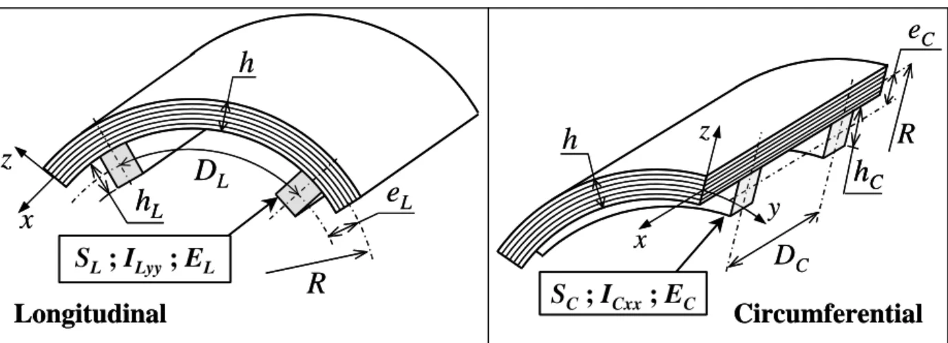
Figure 2: Stiffeners.
As schematized in Fig.2, the cylindrical shell is reinforced using NL and longitudinal and circumferential internal stiffeners, respectively. The corresponding cross-sections and ec-centricities are denoted and (subscript
C N
α
S eα α indicating the type of stiffener:α =L,C). Following the works detailed in Refs.[8,9] and manufacturing requirements, the stiffeners are subjected to the following assumptions:
• The stiffeners are perfectly bounded to the shell.
• They are evenly distributed through the circumference and the length of the shell (see Fig.2):
(
L)
L L R e N D =2π − ; DC =L NC (1) 3e
CR
D
Lh
e
LS
L; I
Lyy; E
Lx
z
Circumferential
Longitudinal
R
D
Cx
y
z
S
C; I
Cxx; E
Ch
h
Lh
Ce
CR
D
Lh
e
LS
L; I
Lyy; E
Lx
z
Circumferential
Longitudinal
R
D
Cx
y
z
S
C; I
Cxx; E
Ch
h
Lh
Lh
Ch
C• They are composed of unidirectional composite plies (of the same material of the shell) of 0° angle with respect to the longitudinal direction of the stiffeners. Thus, the elastic modulus in this longitudinal direction of the stringers and the rings are done by:
1
E E
EL = C = (2)
• The stiffeners are loaded only by traction and bending (in the
( )
xr,yr plane) components, the torsional stiffness being neglected. The bending inertia modulus of the longitudinal and circumferential stiffeners are denoted ILyy and ICxx (in the yr and directions), re-spectively.xr
• They are sensitive to the shear transverse effects.
3 ANALYTICAL STIFFENED COMPOSITE SHELL BUCKLING MODEL
As detailed thereafter, the analytical modeling of the stiffened laminated shell buckling problem is treated similarly to the approach detailed in Ref.[6]. As shown by FE calculus and experimental result validations, such an approach has appeared to exhibit a good sensitivity to lamination parameters. The contribution of the stiffeners is here taken into account by correct-ing the overall laminate stiffness coefficients.
The developed buckling shell model is based on a Third Order Shear Deformable theory (TOSD). Hence, the displacement field is expressed as follows:
(
)
(
)
(
)
(
)
( )
⎪ ⎪ ⎩ ⎪⎪ ⎨ ⎧ = + − + = + − + = 2 3 2 3 3 4 3 4 w y , x W h w z z v z , y , x V h w z z u z , y , x U y y , y x x , x ϕ ϕ ϕ ϕ (3)with F,x meaning ∂F ∂x. Considering the cylindrical shell linear strain-displacement rela-tions, it could be writen:
{ } { }
{ }
⎪ ⎭ ⎪ ⎬ ⎫ ⎪ ⎩ ⎪ ⎨ ⎧ − + + − + + − ⎪ ⎭ ⎪ ⎬ ⎫ ⎪ ⎩ ⎪ ⎨ ⎧ + + + ⎪ ⎭ ⎪ ⎬ ⎫ ⎪ ⎩ ⎪ ⎨ ⎧ + + = + + = ⎪ ⎭ ⎪ ⎬ ⎫ ⎪ ⎩ ⎪ ⎨ ⎧ R v w R v w w h z R v z v u R w v u z z x , x , y y , x xy , y , y , y yy , x , x xx , x , y y , x x , y , y x , x x , y , y , x , a m xy yy xx ϕ ϕ ϕ ϕ ϕ ϕ ϕ ϕ χ χ ε ε ε ε 2 3 4 2 3 3 3 (4) and{ }
⎭ ⎬ ⎫ ⎩ ⎨ ⎧ + − + ⎟ ⎟ ⎠ ⎞ ⎜ ⎜ ⎝ ⎛ − = ⎟ ⎟ ⎠ ⎞ ⎜ ⎜ ⎝ ⎛ − = ⎭ ⎬ ⎫ ⎩ ⎨ ⎧ x x , y y , xz yz w R v w h z h z ϕ ϕ γ ε ε 2 2 2 2 4 1 4 1 2 2Considering the hypothesis related to the stiffeners, the following tensile force and moment resultant components (expressed with respect to the mean-surface of the shell) are expressed as follows: z z M N h h h xx xx x x L d 2 2
∫
− − ⎭ ⎬ ⎫ ⎩ ⎨ ⎧ = ⎭ ⎬ ⎫ ⎩ ⎨ ⎧ σ σ ; z z M N h h h yy yy y y C d 2 2∫
− − ⎭ ⎬ ⎫ ⎩ ⎨ ⎧ = ⎭ ⎬ ⎫ ⎩ ⎨ ⎧ σ σ (5)where hL and are the total height of the stiffeners as depicted in Fig.2. The other terms are not dependant of the stiffeners and are given by:
C h z z M M T T N N h h xy yz xz xy yx xy y x yx xy d 2 2
∫
− ⎪ ⎪ ⎭ ⎪⎪ ⎬ ⎫ ⎪ ⎪ ⎩ ⎪⎪ ⎨ ⎧ = ⎪ ⎪ ⎭ ⎪⎪ ⎬ ⎫ ⎪ ⎪ ⎩ ⎪⎪ ⎨ ⎧ = = σ σ σ σ (6)In that way, and considering the elastic orthotropic constitutive law of the composite cross-plies, these resultants components are done by:
{ }
{ }
{ }
[ ]
[ ]
[ ]
[ ]
[ ] [ ]
[ ]
[ ]
[ ]
[ ]
[ ] [ ]
[ ]
{ }
{ }
{ }
{ }
⎪⎪⎭ ⎪ ⎪ ⎬ ⎫ ⎪ ⎪ ⎩ ⎪ ⎪ ⎨ ⎧ ⎥ ⎥ ⎥ ⎥ ⎦ ⎤ ⎢ ⎢ ⎢ ⎢ ⎣ ⎡ + + + + + + = ⎪ ⎭ ⎪ ⎬ ⎫ ⎪ ⎩ ⎪ ⎨ ⎧ γ χ χ ε a m a a a a E Dˆ D Dˆ D Bˆ B Bˆ B Bˆ B Aˆ A T M N 0 0 0 0 0 (7)using the following laminate stiffness coefficients [MES02]:
(
)
(
)
(
)
(
)
(
k k)
ij ij N k ) k ( ij a ij k k N k ) k ( ij a ij k k N k ) k ( ij ij k k N k ) k ( ij ij k k N k ) k ( ij ij D h A E z z C D z z C B z z C D z z C B z z C A 2 ij 5 1 5 1 4 1 4 1 3 1 3 1 2 1 2 1 1 1 4 ; 5 1 ; 4 1 ; 3 1 ; 2 1 ; − = − = − = − = − = − = − = − = − = − = − =∑
∑
∑
∑
∑
(8)and the additional terms due to the stiffeners:
⎪ ⎪ ⎪ ⎭ ⎪ ⎪ ⎪ ⎬ ⎫ ⎪ ⎪ ⎪ ⎩ ⎪ ⎪ ⎪ ⎨ ⎧ + + − − − = ⎪ ⎪ ⎪ ⎭ ⎪ ⎪ ⎪ ⎬ ⎫ ⎪ ⎪ ⎪ ⎩ ⎪ ⎪ ⎪ ⎨ ⎧ Lyy L L L Lyy L L Lyy L L L L L L L L a a I e S e I S e I e S e S e S D E Dˆ Dˆ Bˆ Bˆ Aˆ 2 4 2 3 11 11 11 11 11 6 3 ; ⎪ ⎪ ⎪ ⎭ ⎪ ⎪ ⎪ ⎬ ⎫ ⎪ ⎪ ⎪ ⎩ ⎪ ⎪ ⎪ ⎨ ⎧ + + − − − = ⎪ ⎪ ⎪ ⎭ ⎪ ⎪ ⎪ ⎬ ⎫ ⎪ ⎪ ⎪ ⎩ ⎪ ⎪ ⎪ ⎨ ⎧ Cxx C C C Cxx C C Cxx C C C C C C L L a a I e S e I S e I e S e S e S D E Dˆ Dˆ Bˆ Bˆ Aˆ 2 4 2 3 22 22 22 22 22 6 3 (9)
the other superscript ˆ coefficients being zero. The governing equations of equilibrium are done by:
(
)
(
)
⎪ ⎪ ⎪ ⎩ ⎪⎪ ⎪ ⎨ ⎧ = + − + − + = − + − + = − + = + + = + 0 2 0 4 0 0 0 R V W V PR T M M W U PR T M M R N T T R T N N N N y , z , y x , xy y , y x , z , x y , yx x , x y y , y x , x y x , xy x , x y , yx x , x (10)where P is the external hydrostatic pressure.
5
The displacement approximation functions satisfying the kinematic boundary conditions are chosen to be harmonic approximation functions defined as follows [5]:
(
) (
)
(
) (
)
(
) (
)
(
) (
)
(
) (
)
⎪ ⎪ ⎪ ⎩ ⎪ ⎪ ⎪ ⎨ ⎧ = = = = = = = = = = R ny L x m a ) y , x ( R ny L x m a ) y , x ( R ny L x m a ) y , x ( w w R ny L x m a ) y , x ( v v R ny L x m a ) y , x ( u u y x w v u sin sin cos cos cos sin sin sin cos cos y y x x π ϕ ϕ π ϕ ϕ π π π ϕ ϕ (11)where m and n are the numbers of longitudinal and circumferential half-waves of the buckling modes.Finally, after substituting the displacement approximations in Eq.(4), the governing relations (10) expressed using the resultants done by Eqs.(5,6) lead to the eigen-value buck-ling problem that can be expressed under a matrix form. As shown in Ref.[6], it can then be easily computed to estimate the buckling pressure Pcr.
4 OPTIMIZATION PROCEDURE
The optimization problems studied in section §5 implies several type of discrete parame-ters (standard angles of laminations, number of composite plies, numbers of rings and string-ers). Hence it requires adequate methods dedicated to discontinuous design space analysis. Moreover, some previous works focusing on the optimal laminations of composite structures subjected to buckling have shown that these problems involve local optima, non-convexity, and then requires global optimization procedures [5,8].
The numerous engineering design problems explored in recent years [10,11] have demon-strated the usefulness and robustness of the genetic algorithms. The main principle is based on an analogy with natural evolution and biologically inspired operators: it manipulates a fixed number of potential design solutions (called individuals) and the fittest ones (leading to the best objective function F values) are likely to survive, to recombine their features and thus to form a renewed population.
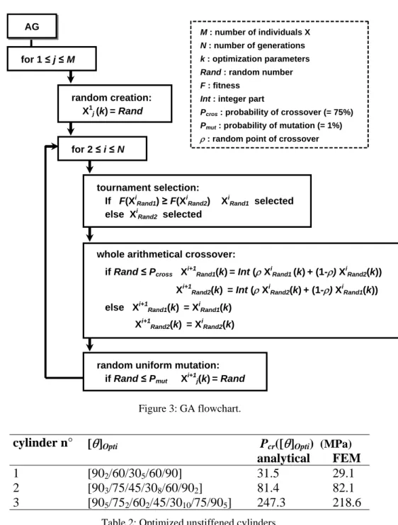
According to results taken from the literature and preliminary tests [5], the computed ge-netic algorithm manipulates directly integer parameters. The starting population is randomly created. The tournament selection, the whole arithmetical crossover and the random uniform mutation are applied. The foremost scheme, the genetic operators (also detailed in Refs.[5,10]) and the corresponding probability values are reminded in Fig.3. The GA finally sends back the best individual found. For the numerical applications performed, the numbers of individu-als and generations have been chosen accordingly to the cardinalities of the optimization problems.
5 NUMERICAL RESULTS
In the next paragraphs, the unstiffened cylinders with the optimized laminations [θ]Opti
(ob-tained in Ref.[6] and reminded in Tab.2) which maximize the buckling pressure have been used as a reference. In that way, the fitness of the calculated optimized stiffened solution has been evaluated using the relative gain η defined as follows:
[ ]
(
)
(
[ ]
)
[ ]
(
Opti)
cr Opti cr R Opti cr P P P θ θ θ η= − (12)where Pcr
(
[ ]
θ ROpti)
is the limit of stability for the stiffened composite shell andPcr(
[ ]
θ Opti)
is the critical pressure of the corresponding unstiffened optimized cylinder. This gain has been evaluated both using analytical and FE results: similarly to the study detailed in Ref.[6],for 2 ≤ i ≤ N
random uniform mutation: if Rand ≤ Pmut X
i+1
j(k)= Rand
whole arithmetical crossover: if Rand ≤ Pcross X i+1 Rand1(k)= Int (ρ X i Rand1 (k)+ (1-ρ) X i Rand2(k)) Xi+1Ran Figure 3: GA flowchart.
cylinder n° [θ]Opti Pcr([θ]Opti) (MPa)
analytical FEM
1 [902/60/305/60/90] 31.5 29.1
2 [903/75/45/308/60/902] 81.4 82.1
3 [905/752/602/45/3010/75/905] 247.3 218.6
Table 2: Optimized unstiffened cylinders.
a FE model using Mindlin laminated shell and beam elements has been also computed on An-sys software. The buckling pressures of the [θ]Opti reference cylinders are also detailed in
Tab.2.
5.1 Optimization of the stacking sequences
In this first approach, the stiffeners characteristics (numbers and geometries) and the num-ber of composite plies are fixed. They are assumed to have equal square cross-sections hL×hL = hC×hC (see Fig.2) with prescribed side lengths done in Tab.3. The optimal design problem
therefore consists to find the optimal laminations [θ]ROpti maximizing the buckling pressure.
The results obtained show very small influence of the longitudinal stiffeners a contrary to the rings. Moreover, it should be noticed that the optimized stacking sequences always exhibit a
7
d2(k) = Int (ρ XiRand2(k)+ (1-ρ) XiRand1(k))
else Xi+1 Rand1(k) = XiRand1(k) Xi+1 Rand2(k) = XiRand2(k) random creation: X1j (k)= Rand for 1 ≤ j ≤ M M : number of individuals X N : number of generations k : optimization parameters Rand : random number F : fitness
Int : integer part
Pcros : probability of crossover (= 75%)
Pmut : probability of mutation (= 1%)
ρ : random point of crossover
tournament selection:
If F(XiRand1) ≥ F(XiRand2) XiRand1 selected
else XiRand2 selected
[
90N1/Ψ1/±30N2/Ψ2/90N3]
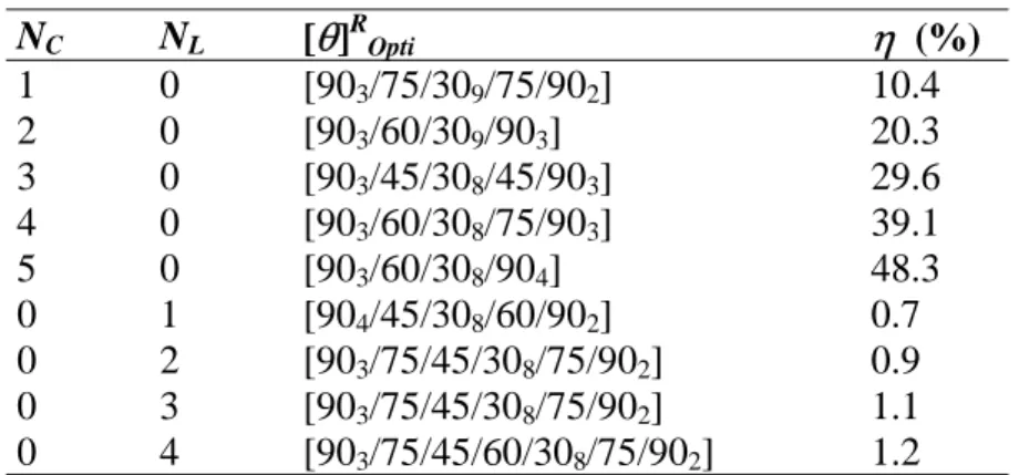
pattern increasing the circumferential rigidity of the shell [5]. The optimized results obtained for the cylinder n°2 (and the corresponding gains calculated using the analytical model) are detailed in Tab.4.cylinder n° 1 2 3
hL, hC 5 8 12
Table 3: Stiffener cross-section dimensions (mm).
NC NL [θ]ROpti η (%) 1 0 [903/75/309/75/902] 10.4 2 0 [903/60/309/903] 20.3 3 0 [903/45/308/45/903] 29.6 4 0 [903/60/308/75/903] 39.1 5 0 [903/60/308/904] 48.3 0 1 [904/45/308/60/902] 0.7 0 2 [903/75/45/308/75/902] 0.9 0 3 [903/75/45/308/75/902] 1.1 0 4 [903/75/45/60/308/75/902] 1.2
Table 4: Optimized laminations of cylinder n°2.
For each cylinder, the best optimized solutions have been checked using the FE model as detailed in Tab.5. As observed previously in Ref.[6], the analytical model overestimate the gains. Nevertheless, the FE results have confirmed the stability limit increases due to circum-ferential stiffeners and optimized laminations.
cylinder n° NC NL [θ]ROpti η (%)
analytical FEM
1 3 0 [902/307/90] 16.8 16.2
2 3 0 [903/45/308/45/903] 29.6 16.2
3 3 0 [905/75/602/45/308/908] 47.1 15.8
Table 5: Examples of optimized solutions.
5.2 Multi-parameter optimization
In this paragraph, the optimization objective consists in the simultaneous determination of the best lamina stacking sequence and stiffener characteristics. The optimization constraint is to use fixed material volumes equal to those of the corresponding unstiffened cylinders (see Tab.1). The circumferential and longitudinal stiffeners have square hC×hC and hL×hL
cross-sections. The optimization problem can then be formulated as follows: find N, [θ]ROpti, NC, hC, NL, hL
leading to a material volume Vc
and maximizing Pcr
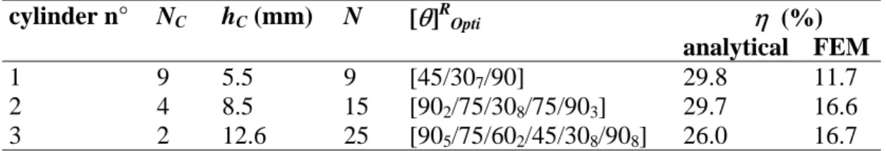
The optimized results are depicted in Tab.6. For each optimization calculus performed, the number of stringers NL obtained has always been zero. It could be noticed that the lamination
pattern of the cylinder n°1 is not exactly preserved due to its low number of composite plies. Nevertheless, the reinforcement solutions obtained tend to maximize the circumferential stiff-ness of the vessels as mentioned previously.
cylinder n° NC hC (mm) N [θ]ROpti η (%)
analytical FEM
1 9 5.5 9 [45/307/90] 29.8 11.7
2 4 8.5 15 [902/75/308/75/903] 29.7 16.6
3 2 12.6 25 [905/75/602/45/308/908] 26.0 16.7
Table 6: Multi-parameter optimization results.
6 CONCLUDING REMARKS
This work devoted to the optimization of stiffened composite underwater hulls subjected to buckling leads to the following concluding remarks:
• As observed for the unstiffened hulls previously studied, the optimized stacking se-quences exhibit a
[
90N1/Ψ1/±30N2 /Ψ2 /90N3]
typical pattern.• In the same way and as observed numerically and experimentally in Refs.[5,6], the circumferential reinforcement plays a major role in the increases of the stability limits for such lengthy hulls: on the contrary of the stringers, the rings provide substantial buckling gains.
• The developed optimization tool allows to guide quickly designers for reinforcement so-lutions: the time of optimization calculus have appeared to be always less than 10 mn on a standard PC. Moreover, the results obtained have also appeared to be reproducible, demonstrating the robustness of the computed GA procedure.
This study provides a reliable tool for the design of large pressure hulls for underwater ap-plications. This method was used for the prospective study of composite buoyancy cans which maintain risers tension in offshore oil production. Another field of investigation is the design of composite deepsea oil/gas separation tanks. The hull of such devices is mainly a large cyl-inder (2~3 meters in diameter, 10 meter long) submitted to high internal and external pressure.
REFERENCES
[1] Vinson J.R., The behavior of shells composed of isotropic and composite materials. Kluwer Academic Pub.,1992.
[2] Graham D., Composite pressure hulls for deep ocean submersibles. Composite
Struc-tures, 32, 331-343, 1995.
[3] Davies P., Chauchot P., Composites for marine applications – part 2: underwater struc-tures. Mechanics of composite materials and structures, Kluwer Academic Pub., 249-260, 1999.
[4] Tsouvalis N.G., Zafeiratou A.A., Papazoglou V.J., The effect of geometric imperfec-tions on the buckling behaviour of composite laminated cylinders under external hydro-static pressure. Composites Part B, 34-3, 217-226, 2003.
[5] Messager T., Optimisation d’enceintes sous-marines composites (Optimization of com-posite submarine hulls). PhD Thesis, Lille University, France, July 2000.
9
[6] Messager T., Pyrz M., Gineste B., Chauchot P., Optimal laminations of thin underwater composite cylindrical vessels. Composite Structures, 58-4, 529-537, 2002.
[7] Papazoglou V.J., Tsouvalis N.G., Zaphiratou A.A., Parametric study of small scale cyl-inders under hydrostatic load: flat rigid end closures. MAST III project MAS3-CT97-0091, report n° STL-073-F-98, National Technical University of Athens, 1998.
[8] Sun G., Optimization of stiffened laminated-composite circular-cylindrical shells for buckling. Composite Structures, 23, 53-60, 1993.
[9] Kallassy A., Marcellin J.L., Optimization of stiffened plates by genetic search.
Struc-tural Optimization, 13, 134-141, 1997.
[10] Michalewicz Z., Genetic algorithms + data structures = evolution programs, third, re-vised and extended edition. Springer Verlag, Berlin, 1996.
[11] Miettinen K., Neittaanmäki P., Mäkelä M.M., Périaux J., Evolutionary Algorithms in Engineering and Computer Science. John Wiley, 1999.