HAL Id: hal-02573638
https://hal.archives-ouvertes.fr/hal-02573638
Submitted on 14 May 2020
HAL is a multi-disciplinary open access
archive for the deposit and dissemination of
sci-entific research documents, whether they are
pub-lished or not. The documents may come from
teaching and research institutions in France or
abroad, or from public or private research centers.
L’archive ouverte pluridisciplinaire HAL, est
destinée au dépôt et à la diffusion de documents
scientifiques de niveau recherche, publiés ou non,
émanant des établissements d’enseignement et de
recherche français ou étrangers, des laboratoires
publics ou privés.
Multi-site Connectivity for Edge Infrastructures
DIMINET:DIstributed Module for Inter-site
NETworking
David Espinel Sarmiento, Adrien Lebre, Lucas Nussbaum, Abdelhadi Chari
To cite this version:
David Espinel Sarmiento, Adrien Lebre, Lucas Nussbaum, Abdelhadi Chari. Multi-site Connectivity
for Edge Infrastructures DIMINET:DIstributed Module for Intersite NETworking. CCGRID 2020
-20th IEEE/ACM International Symposium on Cluster, Cloud and Internet Computing, IEEE; The
University of Melbourne, May 2020, Melbourne, Australia. pp.1-10. �hal-02573638�
Multi-site Connectivity for Edge Infrastructures
DIMINET:DIstributed Module for Inter-site NETworking
David Espinel Sarmiento
Orange Labs Network Orange Lannion, France [email protected]
Adrien Lebre
IMT-Atlantique Inria/LS2N Nantes, France [email protected]Lucas Nussbaum
Université de Lorraine Inria/LORIA Nancy, France [email protected]Abdelhadi Chari
Orange Labs Network Orange Lannion, France [email protected]
Abstract—The deployment of a geo-distributed cloud infras-tructure, leveraging for instance Point-of-Presences at the edge of the network, could better fit the requirements of Network Function Virtualization services and Internet of Things appli-cations. The envisioned architecture to operate such a widely distributed infrastructure relies on executing one instance of a Virtual Infrastructure Manager (VIM) per location and imple-ment appropriate code to enable collaborations between them when needed. However, delivering the mechanisms that allow the collaborations is complex and error prone task. This is particularly true for the one in charge of establishing connectivity among VIM instances on-demand. Besides the reconfiguration of the network equipment, the main challenge is to design a mechanism that can offer usual network virtualization operations to the users while dealing with scalability and intermittent network properties of geo-distributed infrastructures.
In this paper, we present how such a challenge can be tackled in the context of OpenStack. More precisely, we introduce DIMINET, a DIstributed Module for Inter-site NETworking ser-vices capable to interconnect independent networking resources in an automatized and transparent manner. DIMINET relies on a decentralized architecture where each agent communicates with others only if needed. Moreover, there is no global view of all networking resources but each agent is in charge of interconnecting resources that have been created locally. This approach enables us to mitigate management traffic and keep each site operational in case of network partitions. A promising approach to make other cloud-services collaborative on-demand.
Index Terms—IaaS, SDN, virtualization, networking, automa-tion
I. INTRODUCTION
Internet of Things (IoT) applications, Network Function Virtualization (NFV) services, and Mobile Computing [1] have operational constraints that require to deploy computational and storage resources at multiple locations closer to the end users. While the deployment of such distributed cloud infras-tructures (DCIs) has been debated initially due to economical reasons, the question, now, is no more whether they will be deployed but rather how we can operate them?
Among the different approaches that are investigated, the use of a series of independent Virtual Infrastructure Manager (VIM) instances looks to be the most promising one [2], [3]. However VIMs such as OpenStack [4], have been de-signed in a pretty stand-alone way in order to manage a single deployment, and not, to peer each other in order to establish inter-site services. Hence, most VIM services should
be extended with additional pieces of code in order to offer the same functionality but over multiple instances. While the use of distributed databases can help developers implement such inter-site operations at the first sight [5], it is a bit more complicated for a few services, in particular when scalability and network partitions should be taken into account. To illustrate this claim, we propose to address in this paper the challenges related to the inter-site networking services. In particular, we consider the two following points as the cornerstone:
• Layer 2 network extension: being able to have a Layer 2 Virtual Network (VN) that spans several VIMs. This is the ability to plug into the same VN, Virtual Machines (VMs) that are deployed in different VIMs.
• Routing function: being able to route traffic between a VN A on VIM 1 and a VN B on VIM 2.
Obviously, current proposals that leverage centralized ap-proaches such as Tricircle [6] are not satisfactory. The chal-lenge is to establish such inter-site networking services among several VIMs in a decentralized way. By decentralized, we mean that the networking service of a VIM needs to be extended in order to guarantee the following characteristics:
• Scalability: The inter-site service should not be restricted
by design to a certain number of VIMs.
• Resiliency: All parts of a DCI should be able to survive to network partitioning issues. In other words, cloud service capabilities should be operational locally when a site is isolated from the rest of the infrastructure.
• Locality awareness: VIMs should mitigate as much as possible remote interactions. This implies that locally created data should remain local as much as possible, and only shared with other instances if needed, thus avoiding to maintain a global knowledge base.
• Abstraction and automation: Configuration and instan-tiation of inter-site services should be kept as simple as possible to allow the deployment and operation of complex scenarios. The management of the involved implementations must be fully automatic and transparent for the users.
Our contribution to tackle this challenge is the DIMINET proposal, a DIstributed Module for Inter-site NETworking services. To the best of our knowledge this is the first
inter-site service tool that satisfies all of the aforementioned prop-erties. The architecture of DIMINET extends concepts that have been proposed in Software Defined Networking (SDN) technologies, in particular in the DISCO and OpenDayLight SDN controllers [7], [8]: On each site, a module is in charge of managing its local site networking services, and is capable of communicating with remote modules, on-demand, in order to provide virtual networking constructions spanning several VIMs.
We implemented a first proof-of-concept of DIMINET as a module deployed besides the networking service of Open-Stack, Neutron, using an horizontal API to communicate among modules. This approach enabled us to keep the col-laboration code outside the Neutron one. Although additional experiments should be done to validate how our PoC behaves in presence of untimely network disconnections, preliminary experiments conducted on top of Grid’5000 demonstrated the correct functioning of our proposal.
It is noteworthy that the contribution of DIMINET goes beyond the technical contribution on the Neutron OpenStack service. Actually, we are investigating how can the DIMINET proposal be generalized to other services to make them col-laborative with minimal efforts in terms of developments. Indeed, a significant part of the abstractions that has been implemented can be reused to share information in an effi-cient manner between services while mitigating the impact of network partitions. Such generic pieces of code may represent a huge contribution to deliver building blocks for collaboration between independent systems. Such building block are critical to operate and use DCIs such as envisioned in Fog and Edge computing platforms.
The rest of this paper is organized as follows. Section II describes challenges related to inter-site networking services. Section III presents related work. DIMINET architecture is given in Section IV. Preliminary evaluations of our PoC are discussed in Section V. Finally, Section VI concludes and discusses future work.
II. INTER-SITE NETWORKING CHALLENGES
As mentioned before, programming collaboration mecha-nisms between several instances of the same service is a tedious task, especially in a geo-distributed context where net-work disconnections can prevent one instance from synchro-nizing with others for more or less long durations. Considering this point as the norm when designing inter-site services, in particular for the cloud networking ones, brings forth new challenges and questions, In this section, we discuss the major ones. We classified them in two categories: those related to the organization of networking information and those related to the implementation of inter-site networking services.For the sake of clarity, we remind that our DCI architecture is composed of several sites. Each site is managed by a VIM instance, which is itself composed of several services. An inter-site operation consists in interacting with at least two remote instances of the same service.
A. Organization of networking information’s challenges In order to mitigate as much as possible overheads due to data exchanges while being robust enough w.r.t. network dis-connections and partitioning issues, it is important to identify (i) which is the minimal information we have to share and at which granularity, (ii) how this information should be shared and (iii) how the inter-site networking resources that have been created behave in presence of network disconnections.
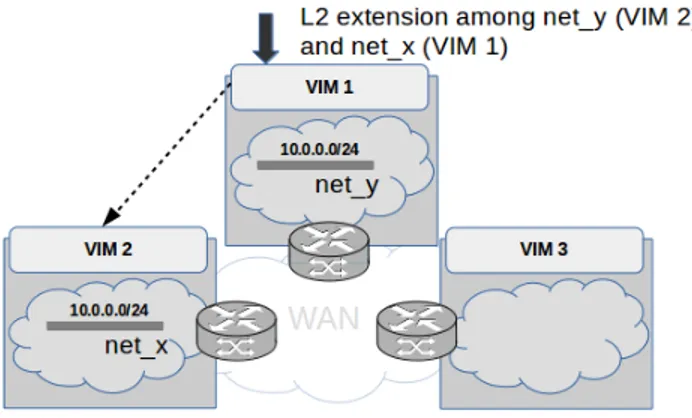
1) Identifying which networking information should be shared: A first aspect to consider is related to the organization of information related to the cloud network resources. For instance, the provisioning of a Layer 2 segment with its respective IP range between two VIMs will require to share information related to the IP addresses that have been allocated at each VIM to avoid conflicts. On the contrary, other informa-tion related to local router gateways, external gateways, fixed host routes . . . may not be likely to be shared with remote sites. In consequence, depending on the inter-site operation, the information that should be shared needs to be well specified to avoid conflicts among the networking management entities. Understanding the different structures that are manipulated by the operations of the networking service will enable the definition of efficient and robust sharding strategies between multiple VIMs.
Fig. 1: Layer 2 extension Request
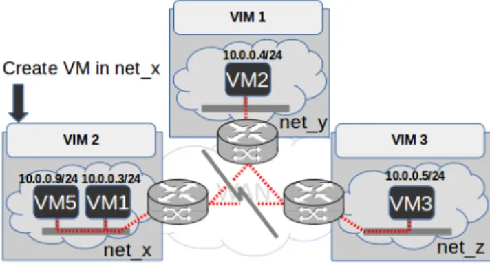
2) Defining how networking information should be shared: A second aspect to consider is related to the scope of each networking service call. Taking into account the scope for each request is critical as sharing information across all VIMs could lead to heavy synchronization and communica-tion needs. For instance,network informacommunica-tion like MAC/IP addresses of ports and identifiers of a network related to one VIM does not need to bes hared with the other VIMS that composed the DCI. Similarly,information related to a Layer 2 network shared between two VIMs as depicted in Figure 2 does not need to be shared with the 3rd VIM. The extension of this Layer 2 network could be done later. That is, only when it will be relevant to extend this network to VIM 3.
3) Facing network disconnections: Each VIM should be able to deliver networking services even in case of network
partitions. Two situations must be considered in this context: (i) the inter-site networking service (for instance a Layer 2 network) has been deployed before the network disconnection and (ii) the provisioning of a new inter-site networking service while some sites cannot be contacted. In the first case, the isolation of a VIM (for instance VIM2 in Figure 2 should not impact the inter-site network elements: VIM2 should still be able to assign IPs to VMs using the "local" part of the inter-site Layer 2 network. Meanwhile, VIM1 and VIM3 should continue to manage inter-site traffic from/to the VMs deployed on this same shared Layer 2 network.
In the second case, because the VIM cannot reach other VIMs due to the network partitioning issue, the information that is mandatory to finalize the provisioning process will be impossible to obtain. The question is whether to decide to completely revoke such a request or if instead it will be desirable to provide the appropriate mechanisms in charge of finalizing the provisioning request partially.
Fig. 2: Operate in a local any mode
B. Implementation challenges
The Networking domain is a large area with multiple standards as well as different technological solutions. To avoid facing heterogeneity issues in the DCI context, the technological choices need to be coordinated in advance in order to ease the networking service provisioning.
1) Standard automatized interfaces: A first aspect to take into account is related to the definition of the vertical and horizontal interfaces to allow the provisioning of inter-site services from the end-users viewpoint but also to make the communication/collaboration possible between the different VIMs. This means that the interface which faces the user (user-side or vertical as traffic flows in a vertical way) and the interface which faces other VIMs (VIM-side of horizontal as traffic flows in a horizontal way) have to be bridged among them. This integration needs to be done in order to provide the necessary user abstraction and the automation of the VIMs communication process.
Consequently, this necessitates the specification and de-velopment of well-defined vertical and horizontal interfaces. These interfaces should present an abstract enough list of the available inter-site networking services and constructions.
2) Support and adaptation of networking technologies: Along with the necessary exchange of networking information among VIMs to provide inter-site services as described in II-A1, the identification of the mechanism to actually do the implementation (i.e., control plane) and allow the VMs traffic to be exchanged (i.e., data plane) will be needed. This implementation information is pretty important since it indicates to each VIM what technologies it should use to forward the VMs traffic and where it should be send (i.e., consider a VM with its private IP address reachable through a VXLAN tunnel endpoint in a physical server with a public IP). Although there are many existing networking protocols to rely on to do the implementation (BGP-EVPN/IPVPN, VXLAN, GRE, Geneve, IPSec, etc.), they will need adaptation in the DCI case. Since the configuration of the networking mechanisms needs to be known by all the participant VIMs in a requested inter-site service, the exchange of additional implementation information will be required among the sites in an automatized way.
This automation is required due to the fact that the user should not be aware of how these networking constructions are configured at the low-level implementation. Since a DCI infrastructure could scale up to hundred of sites, manual networking stitching techniques like [9], [10] will be simply not enough.
Table I summarizes the challenges explained in this section. These challenges will be referenced in the following sections to explain our architectural choices.
III. RELATED WORK
A few solutions have been proposed to deal with inter-site virtualized networking services in IaaS systems [8], [11], [12], [6], [13], [14]. In [12], the authors describes an Hybrid Fog and Cloud interconnection framework to enable a simple and automated provision and configuration of virtual networks to interconnect multiple sites. It sustains the entire manage-ment in a single entity called the HFC manager which is a centralized entity acting as the networking orchestrator. The Tricircle project [6] is also another solution that leverages a centralized architecture. In this proposal, an API gateway node is used as an entry point to a geo-distributed set of OpenStack deployments. Each instance of the Neutron service is not aware of the existence of other Neutron instances, but instead always communicate with the API gateway which is also the only interface exposed to the user. These solutions, which relies on a centralized entity, are not scalable not robust w.r.t. to network partitions.
Among the decentralized approaches that have been de-scribed, we should emphasize the ODL federation project [8] and the DISCO SDN controller [7]. The project Federation for OpenDayLight (ODL) [8] aims to facilitate the exchange of state information between multiple ODL instances by levearging an AMQP communication bus to send and receive messages among instances. The project relies on a fully decentralized architecture where each instance maintains its own view of the system. In that sense, the project might
TABLE I: DCI Challenges summary
Challenge Summary
Organization of networking information’s challenges
Identifying which networking information should be shared Propose good information sharding strategies
Defining how network information should be shared Avoid heavy synchronization by contacting only the relevant sites
Facing network disconnections Continue to operate in cases of network partitioning and be able to recover
Implementation challenges
Standard automatized and distributed interface Well-defined and bridged vertical and horizontal interfaces Support and adaptation of networking technologies Capacity to configure different networking technologies
be a good solution for our objectives in terms of scalability and robustness. However, ODL Federation does not ensure that information related to the inter-site networking resources is consistent across the whole DCI. Actually, the inter-site services are proposed at the controller level while the Neutron instances of OpenStack remain unconscious of the information shared at the ODL level. During a network failure, every Neutron instance will continue to provide its local services without knowing that there are potential conflict-operations when executing actions in resources that are shared between ODLs. Once the connectivity is reestablished, ODLs cannot provide a recovery method and information like IP addresses could be duplicated without coordination among controllers. This is an important flaw for the controller when it needs to recovery from networking disconnections. In the DISCO approach[7], the DCI is divided into several logical groups, each managed by one controller. Each controller peers with the other ones only when traffic needs to be routed. In other words, there is no need to maintain a global view among all instances. However, the design of DISCO is rather simple as DISCO does not a cloud-oriented solution (i.e., it delivers mainly domain-forwarding operations, which includes only conflict-less exchanges). Offering usual VIM operations such as on-demand networks creation, dynamic IP assignment, security groups creation, etc. is prone to conflict and thus is harder to implement.
DIMINET goes one step ahead of these solutions by deliv-ering an inter-site networking service at the cloud level and in a decentralized manner.
IV. DIMINETARCHITECTURE
This section describes the architecture of DIMINET. First, we give a general overview of the architecture. Second, we discuss important design choices, in particular by focusing on how DIMINET instances communicate and how L3 forward-ing and L2 network services have been implemented. Finally and for the sake of clarity, we explain how the network traffic is effectively routed among the different sites.
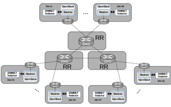
A. Overview
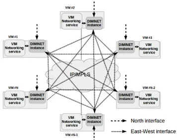
As shown in Figure 3, DIMINET is fully decentralized: each DIMINET instance is deployed besides a VIM networking service.
This architecture guarantees the DCI characteristics as ex-plained as follows.
Fig. 3: DIMINET overview
Scalability: New DIMINET instances representing remotes sites can join the deployment without affecting the normal behaviour of other instances.
Resiliency: Because of the fully distributed architecture, DIMINET does not present the centralized architecture limita-tions. This means that in case of network partitions, as every DIMINET instance and its respective VIM are independent of the others, they will continue to provide, at least, their cloud services locally.
Locality awareness: Because of its horizontal commu-nication between instances that happens only on demand, DIMINET does not build a global knowledge but instead relies on the collaboration among instances to share the necessary inter-site service-related information.
Abstraction and automation: Thanks to its rather simple but powerful APIs, DIMINET does the creation and configura-tion of inter-site services in an automatic way without further actions needed from the user besides the initial service creation request.
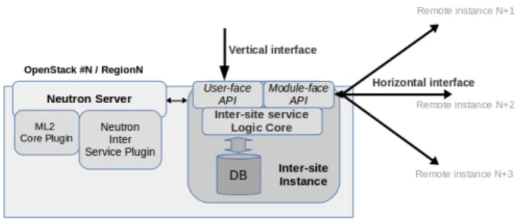
Figure 4 depicts more in detail the internal architecture of a DIMINET instance. It is composed of the communication interfaces, which allows collaboration among VIMs and end-users, and the logic core, which implements the necessary strategies to manage and deploy inter-site services.
Fig. 4: DIMINET architecture
B. Logic Core
The core of DIMINET is the Logic Core, which is in charge of the actual management and coordination of the inter-site services, including communication when required with other DIMINET instances and with the VIM’s Network service (in our case the Neutron service from OpenStack).
In order to effectively address the consistency challenge detailed in II-A1, the information sharding strategy for each service is defined in the Logic Core.
The Logic Core stores inter-site service information in a local database. To relate the same inter-site service stored in different locations, the Logic Core generates a global unique identifier that will identify the same service either in Site 1 or Site N of the service. This global identifier will be created at the DIMINET instance that receives the initial user vertical request and will be transmitted to remote sites inside the horizontal creation request. In this way, all sites will be capable to reference the same inter-site service.
Table 5 shows the schema of the objects used by the Logic Core to represent an inter-site resource.
• Service: Main object of DIMINET which represents the inter-site service. A service is composed by some Param-eters, a list of Resources, and a list of local Connections.
• Param: As we already mentioned, since every proposed
inter-site feature has their own needs, it is necessary to store different information per service. The Param class is used to store service-related information to support the main functionalities of the Logic Core. If for instance, the Service is of L3 type, it will not store information into the All_pool parameter. At the contrary, an L2 service will store the IP allocation pool assigned by the master instance.
• Resource: A Resource represents a virtual networking object belonging to a site. The Service class holds a list of resources (the local one and a series of remote ones). This list exists in every DIMINET instance composing a service.
• Connection: A Connection represents the mechanism
enabling the interconnection for resources to contact or be contacted by remote VIMs in order to forward/route VMs traffic. Unlike Resources objects, Connections are only stored locally.
Service
Global_ID Name Type Params Ressources Connections
Param
ID All_pool Local CIDR IPv Service_Global_ID
Resource
UUID Site Service_Global_ID
Connection
UUID Service_Global_ID
Fig. 5: DIMINET database relationship diagram
We emphasize that for each inter-site resource, there is a master in charge of maintaining the consistency of the related information. In our current model, the master is defined as the VIM that received the initial service request. The use of a more advanced database engine leveraging CRDT [15] would probably be relevant. However, answering this question is let as future work as this does not change the key concepts of DIMINET (i.e., for each resource, there is a mechanism used to maintain the consistency of the information). The use of a per resource master enables DIMINET to deal with network partitions for inter-site resources in a straightforward manner: When an end-user request cannot be satisfied due to network issues (either a remote site cannot be reached or reciprocally when a remote site cannot interact with the master), the request is simply revoked and a notification is sent to the end-user, who is in charge of invoking it once again later.
C. Communication Interfaces
To accept end-user requests and make communication among VIMs possible, DIMINET relies in a two interface division (inspired from the DISCO SDN controller): the North interface and the East-West interface as depicted in Figure 3. These two interfaces are coupled among them and with the Logic Core in order to automatize the inter-site service provisioning.
Both North and East-West interfaces are REST APIs us-ing standard HTTP traffic presentus-ing to the users and to remote instances Create/Read/Update/Delete actions (CRUD). The implemented vertical and horizontal CRUD and their explanation are summarized in Table II.
1) North interface: The north or vertical interface allows the user to request the establishment of inter-site network-ing services among several sites. This interface exposes an abstract-enough API to allow the user to execute CRUD actions on inter-site services. For instance, if the user wants to create a new inter-site service, it has to provide the list of resources that will compose the service and the type of service.
2) East-West interface: Once the networking instance re-ceives an inter-site networking provisioning request from the user using the North interface, it will communicate with the appropriate distant instances using the East-West interface.
This interface allows DIMINET instances to communicate with the relevant neighbor instances to exchange information about the distant networking objects and to request the creation of the symmetric remote inter-site service. The exchanged information are both the logical information to do the dis-tributed management of the networking constructions and the necessary implementation low-level mechanism information allowing the communication of the virtualized instances.
This interface is only used on-demand and with service-related instances. In other words, contacting only the relevant sites for a request will mitigate the network communication overhead and the limitations regarding scalability as well as network disconnections.
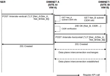
D. Layer 3 routing
The inter-site Layer 3 routing feature is provided for traffic to be routed among different virtual networks (VN) subnetworks. By design, subnetworks should not overlap. That is, the range of addresses in one subnetwork should be unique compared to all other subnetworks. If two subnetworks overlap, when a router needs to send a packet to an IP address inside that range of overlapped addresses, the router may forward the packet to the wrong subnetwork. In this context, the organization of the information of the local VN subnetwork does not need to be coordinated with remotes VIMs, but for the service to be correctly provided, the VN subnetworks Classless Inter Domain Routing (CIDRs) must not overlap.
Let be {SN1, SN2, SN3, ..., SNn−1, SNn} a set of
inde-pendent subnetworks deployed on n VIM sites which are requested to have L3 routing among them. The condition Tn
i=0SN (CIDR)i= ∅ (the sets of subnetworks CIDRs have
to be disjoint sets) needs to be true for traffic to be routed. This verification is done on the first instance that receives the service request. Once the user provides the identifiers of the resources to interconnect in a Layer 3 service and the site
North Interface
Operation Prefix Description
GET /intersite-vertical Retrieve local information of all services
POST /intersite-vertical Create a new service DELETE /intersite-vertical/{global_id} Delete a service with id
global_id
GET /intersite-vertical/{global_id} Retrieve local information of service with id global_id PUT /intersite-vertical/{global_id} Modify a service with id
global_id East-West interface
Operation Prefix Description
POST /intersite-horizontal Horizontal request to create a service
DELETE /intersite-horizontal/{global_id} Horizontal request to delete a service with id global_id GET /intersite-horizontal/{global_id} Read the distant parameters of
a service with id global_id PUT /intersite-horizontal/{global_id} Horizontal request to modify
a service with id global_id
TABLE II: REST API Operations
where they belong, the instance proceeds to query the network information from every pertinent sites to ensure that the IP ranges are not overlapping among them. Once this condition is verified, the instances do the exchange of information to allow the low-level mechanism to do the virtualized traffic forwarding.
Fig. 6: DIMINET L3 Routing service sequence diagram For example, if the user requests to the DIMINET instance of VIM A a Layer 3 routing service among two networks A and B, belonging to VIMs A and B respectively, this DIMINET instance will contact the remote site in order to find the subnetwork CIDR related to the remote network, and of course, it does the same search locally. Consider the IPv4 CIDRs 10.1.2.0/23 and 10.1.4.0/23 for network A and B respectively. The DIMINET instance will do the overlapping verification with the ranges [10.1.2.0-10.1.3.255] for 10.1.2.0/23 and [10.1.4.0-10.1.4.255] for 10.1.4.0. Thus, 10.1.2.0/23T 10.1.4.255/23 = φ (the two subnetworks do not overlap). Since the verification is satisfactory, DIMINET instance A will send a horizontal service creation request to instance B with the information of the two resources and the type of service. Then, the instance A proceeds to send its local information for the data place connection to instance B. The same information is sent as an answer in order for both sites to have the respective reachability information. Figure 6 shows the sequence diagram of the communication among the users and the DIMINET instances when no overlapping is verified. Obviously, when CIDRs overlap, DIMINET does not satisfy the request and notifies the user that the service cannot be provided due to overlapping subnetworks CIDRs.
Finally, DIMINET instances then only interact with the master of the L3 resource each time a site wants to join or leave this network.
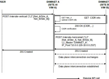
E. Layer 2 extension
The inter-site Layer 2 extension feature gives the possibility to plug into the same virtual network, VMs belonging to different sites. To belong to the same virtual network, hosts must have the same subnetwork prefix (CIDR) and do not have
duplicate MAC or IP addresses. Since every network exists as an independent network in each site, they can each one have their own DHCP service for IP assignment. Thus, MAC and IP assignment have to be coordinated among the requested sites in order for the service to be correctly provided.
At this point, there are two operations that need to be considered over VNs: the join and the extension. The join operation refers to combining multiple independent L2 re-sources to create a single L2 resource. This implies that every independent L2 resource could have already deployed VMs on it. If the join operation is applied between two resources, it will be potentially necessary for each VIM to change the IP addresses already allocated and thus, interrupting the services that are being provided by those VMs, which is not desirable in operational environments. The extension operation refers to expanding one of the L2 resources into the others to create a single L2 resource. This implies that these resources need to be clean in order to do the initial request. Since this last operation does not impact the operation of every segment, we preferred to use it in our design.
For this reason, we have decided to propose the following approach:
• The instance receiving the initial service request assumes the role of master for that particular service.
• This master instance does a logical split of the range of IP addresses within the same CIDR between, for instance, two VIMS at the creation of the inter-site L2 network. In this sense, the master instance will be in charge of provid-ing the IP allocation pools to the other instances composprovid-ing the service, and thus, to do the L2 extension. To avoid to spend all the IP addresses from the first service request, the master instance delivers mid-sizes allocation pools to the other participants. If in any case, one of these instances needs more IP addresses or a new instance arrives to compose the service, it will be enough with querying the master instance to have a new allocation pool.
With this approach, we will avoid the communication over-head of sharing the information between the concerned VIMS each time an IP address is allocated to one resource. At the same time, we will avoid the static division of only doing a CIDR allocation pool division at the service creation time. This approach will allow the instances to maintain a segment logic division while providing a more dynamic sharding strategy.
With our approach, if the user requests to the DIMINET instance of VIM A a Layer 2 extension service to a VIM B, this DIMINET instance will contact the instance of site B in order to verify that a corresponding subnetwork CIDR can be created. If so, the instance of site B will create the corresponding subnetwork and the instance of Site A will take the role of master of that specific L2 inter-site resource. This implies that this instance will decide how to do the CIDR IP allocation pool among the participant sites for the request and to manage further requests concerning the modification of the service.
This information of the master instance as well as the allocated IP range will be sent through the East-West interface
Fig. 7: DIMINET L2 extension service sequence diagram
to remote instances sharing this L2 inter-site resource. When receiving the horizontal L2 creation request, remote instances will store the service information in their local database and will use the service-related information dictated by the master instance to do the appropriate changes in local networking constructions (i.e., change the local IP allocation pool). This changes are also done in the master site to provide the afore-mentioned logical division. Once this is done, the instances proceed to exchange the necessary implementation information to allow VMs traffic to be forwarded among them. Figure 7 shows the sequence diagram of the communication among the users and the DIMINET instances when the same CIDR is verified.
F. Virtualized traffic interconnection
As we proposed DIMINET to be deployed besides Neu-tron, we do not implement the information exchange for the virtualized traffic connectivity over the horizontal interface, but instead we rely on the Interconnection Service Plug-in [11]. The Interconnection plug-Plug-in allows to create an "interconnection" resource which references a local resource (e.g. network A in VIM1) and a remote resource (e.g. network B in VIM2) having the semantic informing that connectivity is desired between the two sites. The proposition then leverages the use of Border Gateway Protocol based Virtual Private Networks (BGPVPNs) [9] at both sides to create an overlay network connecting the two local segments.
The BGPVPN Service Plug-in itself uses the well-known networking protocol BGP for the establishment of IPVPN/EVPN [16], [17]. In BGP-based VPNs, a set of identi-fiers called Route Targets are associated with a VPN. Similarly to the publish/subscribe pattern, BGP-peers use an export and import list to let know the interest of receiving updates about announced routes. A Route Target export identifier is used to advertise the local routes of the VPN to the other BGP-peers. At the other hand, a Route Target import identifier is used to import remote routes to the VPN. For instance, two
sites belonging to the same BGP-VPN will have the following informations to exchange their BGP routes: site A will have route-target-export 100and route-target-import 200, while site B will have route-target-export 200 and route-target-import 100.
V. PROOF-OF-CONCEPT
In this section, we discuss preliminary evaluations we performed on top of a proof-of-concept (PoC) we implemented to experimentally assess the DIMINET architecture.
Since OpenStack already posses an authentication service (Keystone) that is used for client authentication, service dis-covery and authorization, we rely on this service to find out distant DIMINET instances knowing that they are deployed in the same IP address as Neutron.
A. Testbed and setup
Fig. 8: DIMINET testbed setup
Figure 8 shows the experimental platform: each gray box corresponds to a physical machine of Grid’5000 on which a Devstack version of the OpenStack Stein release has been deployed with the following networking services: ML2 OVS driver, neutron-interconnection Plug-in, networking-bgpvpn Plug-in, and networking-bagpipe driver, and a DIMINET instance. This federation of Devstack enabled us to emulate our DCI infrastructure.
Since the Interconnection Service Plug-in also relies in the BGPVPN Service Plug-in, it is necessary to either deploy a BGP peering overlay on top of the IP WAN connectivity or have a BGP peering with WAN IP/MPLS BGP-VPN underlay routing instances. Because Grid’5000 does not allow to inter-act with the physical routers (underlay BGP), we deployed the first scenario using GoBGP [18] to provide the functionality of the BGP instances in each site. These BGP instances are deployed on the same Grid’5000 machines used for the Open-Stack and DIMINET deployments. Moreover, we deployed some Route Reflector (RR) instances in independent physical machines to advertise the BGP VPN Route Targets used to advertise the routes of the virtual networking constructions.
We have deployed 14 sites in total, each RR is connected to 3 sites and the BGP sessions are pre-configured among them and among each RR and its BGP instances clients in each site.
B. Evaluation: Inter-site networking services deployment The first purpose of this demonstration is to show the feasibility of using a distributed architecture to create inter-site networking services. For this, we measured the time needed to create the inter-site service for both kind of services. Since the data plane interconnection depends on the number of instances booted at every segment, we do not measure this time but instead we rely on former works on BGP performance proving the benefits and disadvantages of BGP VPN routes exchanges [19], [20].
Each test has been executed 100 times and Table III sum-marizes the creation time of services varying the quantity of resources/sites by service up to N=6 sites. Moreover, Figure 9 shows a graphical representation of this service mean creation time with the standard error.
Feature # of sites per request
2 3 4 5 6
L3 routing 3.5006 3.56017 3.61324 3.8076 4.08032 L2 extension 3.47927 3.66885 3.98471 4.07191 4.40295
TABLE III: Performance measure time in seconds 1) Layer 3 routing service: For every experiment a random instance has been chosen to receive the user request and start the inter-site Layer 3 routing service creation. These experiments have been done using resources/sites of size 2, 3, 4, 5, and 6.
As explained in the last section about the L3 routing sharding strategy, the time needed to create the L3 service is divided in the following elements:
• The first DIMINET instance requests the pertinent remote sites about the network-related information to find out the subnetworks’ identifiers. In our PoC, this is done in parallel because remote network information can be provided without dependency among the requests.
• The first DIMINET instance proceeds to query the sub-network related CIDR information. Similarly to the pre-vious step, this is done in parallel.
• Once the DIMINET instance finished to query, it does the overlapping verification locally.
• Since the verification is false, the instance proceeds to
call the neutron-interconnection Plug-in to create the interconnection resources.
• Next, the instance sends in parallel the horizontal create
API request to the remote DIMINET instances. The instance waits for remote answers in order to continue.
• Once all the remote instances answered the horizontal request, the first instance proceeds to answer the original user request.
2) Layer 2 extension service: Similarly to the L3 service, for every experiment a random instance has been chosen to receive the user request and to start the inter-site Layer 2 extension service creation. This experiments have been done using resources/sites of size 2, 3, 4, 5, and 6.
2 3 4 5 6 7 8 9 10 11 12 13 14 0 2 4 6 8 10 n T ime(seconds) L3routing L2extension
Fig. 9: DIMINET mean time service creation and standard error
As explained in the last section about the L2 extension sharding strategy, the time needed to create the L2 service is divided in the following elements:
• The first DIMINET instance requests the pertinent remote
sites about the network-related information to find out if the CIDR is available to use. Similarly to the L3 service, this is done in parallel. This means that this first request depends on the time expended by remote sites to answer the query
• Once the DIMINET instance finished to query, it verifies that the CIDR is available for all the requested resources.
• Since the verification is true, the instance creates a special Parameter to gather the IP allocation pools and does the splitting of the same among the remote sites.
• Then, the instance proceeds to call the neutron-interconnection Plug-in to create the neutron-interconnection re-sources.
• The instance proceeds to do the change of the DHCP
parameters of its local resource according to the splitting done by itself.
• Next, the instance sends the horizontal create API request
to the remote DIMINET instances. In this request the additional information about the master identity and the allocated pool for the remote sites are added. The instance waits for remote answers in order to continue.
• Once all the remote instances answer the horizontal request, the first instance proceeds to answer the original user request.
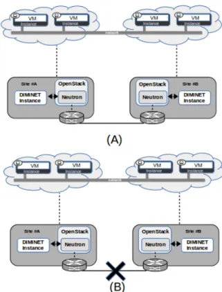
C. Evaluation: Inter-site networking services Resiliency The second purpose of this demonstration is to show the improved resiliency of a distributed architecture against net-working partitioning issues. To explain this, we have deployed an L2 extension service with CIDR IPv4 10.0.0.0/24 depicted in Figure 10 (A) among sites A and B. Once the service has
been deployed, two VMs have also been deployed on each site.
Fig. 10: DIMINET Resiliency test. (A) Initial deployed ser-vice. (B) Inter-site service in presence of networking partition-ing
Firstly, we have checked that the traffic was being carried at the intra-site level, this is, between the VMs deployed in the same site. We also checked that the traffic was being carried at the inter-site level. At this point, thanks to the different technologies used (BGP routes exchanges, VXLAN tunnels among sites . . . ), traffic was correctly forwarded in both cases. Secondly, we emulated a network disconnection using Linux Traffic Control (TC) to introduce a network fault in the link between the sites as shown in Figure 10 (B). We decided to impact in the network allowing the BGP routes exchanges. We verify that while intra-site traffic continues to being forwarded, inter-site traffic will continue to be forwarded a little more until the local BGP router finds that its distant BGP peer is no longer reachable. At that point the local BGP router decides to withdraw the remote routes from its local deployment, then impacting the inter-site data plane traffic.
Traffic Scenarios
Before failure During failure After failure
Intra-site 3 3 3
Inter-site 3 7 3
Because of the independence between the deployments and the logical division done by our DIMINET instance, we effectively arrived to instantiate new VMs during the net-work failure. This corresponds to the behaviour we expected since the OpenStack deployments are completely independent among them.
Finally, when connectivity is reestablished, inter-site traffic takes some time to be forwarded again between sites. This is because the BGP peers waits the configured Keep Alive time to query the distant peer about its availability to reestablish the BGP peering among them, thus, impacting on the time needed to reestablish the traffic. Table IV summarizes whether the traffic is routed either in intra-site or inter-site.
D. Summary
Although these experiments enables the validation of our PoC in terms of behaviour, deeper investigations should be performed in order to clarify some trends. In particular, we need to understand why the time to create an inter-site resource increases w.r.t. to the number of sites involved. Conceptually speaking this is a non sense as all internal requests are handled in parallel. Moreover, we plan to perform additional experiments to stress DIMINET by requesting the creation of several inter-site resources simultaneously and across different groups of sites. Such experiments should demonstrate also the good properties of DIMINET as master roles are distributed among the different instances of our DCI. Obviously, this can lead to hotspots where some VIMs will be much more stressed than others. However, these possible hotspots issues are due to the locality-awareness as well as the resiliency w.r.t. network partitions properties we are looking for.
VI. CONCLUSIONS
In this article, we have introduced DIMINET, a DIstributed Module for Inter-site NETworking services capable to provide automatized management and interconnection for independent networking resources. DIMINET relies on a decentralized architecture where each instance is in charge of managing its local site networking services, and is capable of communi-cating with remote instances, on-demand, in order to provide virtual networking constructions spanning several VIMs. To assess the design of our proposal, we implemented a first PoC that extends the OpenStack Neutron service. We evaluated it through a set of experiments conducted on top of Grid’5000. Preliminary results demonstrated that the DIMINET model can address the challenge of inter-site resources without requiring intrusive modifications at the VIM level.
We are currently conducting additional experiments in order to identify the time-consuming steps in the creation of inter-site resources. We also plan to achieve additional experiments to validate how DIMINET behaves in presence more complex service requests scenarios, in particular in the presence of simultaneous operations.
In parallel to these experimental studies, we are investigat-ing how the use of advanced database engines can improve the robustness of the DIMINET master concept. Across this study,
we identified the opportunity to deliver a more general model of DIMINET. A model that can deal with more services than just the networking one and deliver building blocks capable of handle the life cycle of inter-site resources in a DCI resource management system.
ACKNOWLEDGEMENT
All developments related to this work have been supported by Orange Labs and Inria in the context of the Discovery Open Science initiative. Experiments were carried out using the Grid’5000 testbed, supported by a scientific interest group hosted by Inria and including CNRS, RENATER and several Universities as well as other organizations.
REFERENCES
[1] A. Bousselmi, J. F. Peltier, and A. Chari, “Towards a Massively Distributed IaaS Operating System: Composition and Evaluation of OpenStack,” IEEE Conference on Standards for Communications and Networking, 2016.
[2] D. Sabella, A. Vaillant, P. Kuure, U. Rauschenbach, and F. Giust, “Mobile-Edge Computing Architecture: The role of MEC in the Internet of Things,” IEEE Consumer Electronics Magazine, vol. 5, no. 4, pp. 84– 91, Oct 2016.
[3] R.-A. Cherrueau, A. Lebre, D. Pertin, F. Wuhib, and J. M. Soares, “Edge Computing Resource Management System: a Critical Building Block!” HotEdge, 2018.
[4] OpenStack, “OpenStack,” https://docs.openstack.org/latest/, 2020. [5] A. Lebre, J. Pastor, A. Simonet, and F. Desprez, “Revising OpenStack
to Operate Fog/Edge Computing Infrastructures,” IEEE International Conference on Cloud Engineering, 2017.
[6] OpenStack, “Tricircle Project,” https://wiki.openstack.org/wiki/Tricircle, 2018.
[7] K. Phemius, M. Bouet, and J. Leguay, “DISCO: Distributed Multi-domain SDN Controllers,” Network Operations and Management Sym-posium, 2014.
[8] OpenDayLight, “OpenDaylight Federation Application,” https://wiki. opendaylight.org/view/Federation:Main, 2016.
[9] OpenStack, “Neutron BGPVPN Interconnection,” https: //docs.openstack.org/networking-bgpvpn/latest/, 2019.
[10] ——, “Neutron Networking-L2GW,” https://docs.openstack.org/ networking-l2gw/latest/readme.html, 2019.
[11] ——, “Neutron-Neutron Interconnections,” https://specs.openstack.org/ openstack/neutron-specs/specs/rocky/neutron-inter.html, 2018. [12] R. Moreno-Vozmediano, R. S. Montero, E. Huedo, and I. Llorente,
“Cross-Site Virtual Network in Cloud and Fog Computing,” IEEE Computer Society, 2017.
[13] OpenStack, “KingBird Project,” https://wiki.openstack.org/wiki/ Kingbird, 2019.
[14] F. Brasileiro, G. Silva, F. Arajo, M. Nbrega, I. Silva, and G. Rocha, “Fog-bow: A middleware for the federation of iaas clouds,” 16th IEEE/ACM International Symposium on Cluster, Cloud and Grid Computing, 2016. [15] N. Preguica, J. M. Marques, M. Shapiro, and M. Letia, “A commutative replicated data type for cooperative editing,” in 2009 29th IEEE Inter-national Conference on Distributed Computing Systems. IEEE, 2009, pp. 395–403.
[16] E. Rosen and Y. Rekhter, “BGP/MPLS IP Virtual Private Networks (VPNs),” Internet Requests for Comments, RFC Editor, RFC 4364, February 2006. [Online]. Available: https://tools.ietf.org/html/rfc4364 [17] A. Sajassi, R. Aggarwal, N. Bitar, A. Isaac, J. Uttaro, J. Drake, and
W. Henderickx, “ BGP MPLS-Based Ethernet VPN,” Internet Requests for Comments, RFC Editor, RFC 7432, February 2015. [Online]. Available: https://tools.ietf.org/html/rfc7432
[18] OSRG, “GoBGP,” https://osrg.github.io/gobgp/, 2019.
[19] F. Palmieri, “VPN scalability over high performance backbones eval-uating MPLS VPN against traditional approaches,” Proceedings of the Eighth IEEE International Symposium on Computers and Communica-tion, 2003.
[20] J. Mai and J. Du, “BGP performance analysis for large scale VPN,” 2013 IEEE Third International Conference on Information Science and Technology, 2013.