Recherche Scientifique
Université Echahid Hamma Lakhdar d’El-Oued
FACULTE DE TECHNOLOGIE
DEPARTEMENT DE GENIE MECANIQUE
Présenté pour l’obtention du diplôme de
Mémoire de fin d’étude
MASTER ACADEMIQUE
Domaine: Sciences et Technologie
Filière: Génie mécanique
Spécialité: Energétique
Thème
2017-2018
Présenté par
FERDJANI Abdelfettah YAHIA AbdennourDevant le jury composé de
UEHL El-Oued Président
MCA ATTIA Mohammed El-Hadi
UEHL El-Oued Examinateur
MCB REKBI Fares Mohammed Laid
UEHL El-Oued Encadreur
MCA ATIA Abdelmalek
Contribution to the Simulation of Coupled
Transfers Phenomenon
To our parents,
To our families,
We would like to thank to our supervisor. Dr.
Abdelmalek Atia for his guidance,
suggestions and comments. We also thank all staff of Mechanical Engineering
Department for their information's and supports. We would also like to thank the
lecturers who have been engaged in correcting our mistakes and working on our
evaluation. In the last we express sincere thanks to our families for their support and
for their understanding in every step of our education.
v
ACKNOWLEDGMENTS ... iv
LIST OF TABLES ... viii
LIST OF FIGURES ... ix
NOMENCLATURE ... x
LATIN LETTERS ... x
GREEK LETTERS ... xi
INDICES AND EXHIBITORS ... xii
GENERAL INTRODUCTION ... 1
CHAPTER I Fuel Cell Systems Concepts and Description ... 3
I.1.Introduction ... 4
I.2 Types of Fuel Cell ... 5
I.2.1 Polymer Electrolyte Membrane (PEM) Fuel Cell ... 5
I.2.2 Alkaline Fuel Cell ... 5
I.2.3 Phosphoric Acid Fuel Cell ... 6
I.2.4 Solid Oxide Fuel Cell ... 6
I.2.5 Molten Carbonate Fuel Cell ... 7
I.3 Research on Proton Exchange Membrane Fuel Cell ... 7
I.4 PEM Fuel Cell: Description ... 8
I.4.1 the differences between the two PEMFC variants ... 9
I.5 PEM Fuel Cell Components ... 10
I.5.1 Polymer Electrolyte Membrane ... 10
I.5.2 Gas Diffusion Layer (GDL) ... 11
I.5.3 Catalyst Layer ... 11
I.5.4 Bipolar / End Plates ... 12
I.5.4.1 Serpentine Shaped Gas Flow Channel ... 13
I.5.4.2 Parallel/Straight Shaped Gas Flow Channel ... 13
I.5.4.3 Discontinuous Type Gas Flow Channel ... 14
I.5.4.4 Spiral Shaped Gas Flow Channel ... 14
I.6 Conclusion ... 14
CHAPTER II Working principles of the Fuel cell ... 15
II.1 Introduction ... 16
II.2 Physico-chemical phenomena in a PEM fuel cell ... 16
II.2.1 Fluidic phenomena ... 16
II.2.2 Thermal phenomena... 17
vi
II.2.2.4 Entropy of half-reactions ... 20
II.2.3 Electrochemical phenomena ... 20
II.2.3.1 The loss of activation ... 21
II.2.3.2 Ohmic losses ... 21
II.2.3.3 The loss of concentration ... 21
II.3 Thermodynamics of Chemical Reactions ... 22
II.3.1 Free Energy Change of Chemical Reactions ... 22
II.3.2 Standard Free Energy Change of a Chemical Reaction The chemical ... 22
II.3.3 Relation Between Free Energy Change in a Cell Reaction and Cell Potential ... 23
II.3.4 Nernst Equation ... 24
II. 4 Water Management ... 26
II.4.1 Transfers of water in cell ... 27
II.4.2 Effect of operation condition in water management ... 28
II.4.2.1 Humidity ... 28
II.4.2.2 Flow rate ... 28
II.4.2.3 Temperature ... 29
II.4.2.4 Pressure ... 29
II.4.3 Thermal management... 29
II.4.3.1 influence of freezing ... 29
II.4.3.2 Start up from freezing ... 29
II.4.3.3 Influence high temperature ... 29
II.5 Conclusion ... 29
CHAPTER III Mathematical modeling ... 30
III.1.Introduction ... 31
III.2 Physical Model ... 31
III.2.1 Geometry of the modeled structure ... 31
III.2.2 Model assumptions ... 31
III.3 Mathematical equations ... 32
III.4 Numerical simulation ... 36
III.4.1 Simulation tool (FLUENT ANSYS) ... 36
III.4.2 Presentation of the mesh ... 37
III.4.3 Boundary conditions ... 38
III.5 Modeling parameters ... 38
III.5.1 Geometric parameters ... 38
vii
III.5.4 Material transport parameters ... 40
III.5.5 Definition of material characteristics... 40
III.5.6 Thermophysical properties ... 40
III.6 Conclusion ... 42
CHAPTER IV Numerical Simulation of PEMFC using ANSYS FLUENT ... 43
IV.1 Introduction ... 44
IV. 2 Thermal profiles ... 44
IV.2.1. Distribution of temperature in the anode gas diffusion layer (GDL) ... 44
IV.2.2. Distribution of temperature in the cathode gas diffusion layer (GDL) ... 46
IV.3 Distribution of the molar fractions of gases in the gas diffusion layer ... 46
IV.3.1 Distribution of the molar fraction of hydrogen ... 46
IV.4 Oxygen and hydrogen concentration in the gas diffusion layer GDL ... 47
IV.6 Velocity Profile in the gas diffusion layer GDL ... 49
IV.7 Conclusion ... 54
GENERAL CONCLUSION ... 55
viii
Table I.1. The differences between the two PEMFC variants 10 Table II.1: Expressions of terms "ST" heat sources
Table II.2: Expressions of concentration overvoltages
18 21 Table III.1: The source terms of the governing equations. 36 Table III.2: The geometrical parameters used in the model. 38
Table III.3: Parameters of reaction kinetics. 39
Table III.4: Input parameters. 39
Table III.5: Transport Parameters Used in the Modeling. 40 Table III.6: Physical properties of the fluid used in the simulation. 41 Table III.7: Actual thermal conductivities and specific heats of the environments considered 41
ix
Figure I.1. Schematic of a PEM fuel cell. 4
Figure I.2: Operating principle of alkaline type fuel cells 5 Figure I.3: Operating principle of solid oxide fuel cells 6 Figure I.4: Operating principle of molten carbonate fuel cells 7 Figure I.5: Schematic of a PEM fuel cell showing the main reactions (Mattuci 2001) 8 Figure I.6: Schematic view of a PEM fuel cell and its operating principles 9
Figure I.7: The Image of fuel cell catalyst 11
Figure I-8: Serpentine shaped gas flow channel configuration 13 Figure I.9: Parallel gas flow channel configuration 13
Figure I-10: Spiral flow field configuration 14
Figure II.1: Occurrence processes in a PEM fuel cell 26 Figure II.2: Mechanisms of water transport in the membrane 27 Figure III.1: Presentation of different areas of study of PEMFC. 32
Figure III.2: General simulation procedure 37
Figure III.3: General presentation of the mesh (GDL) 37 Figure IV.1: Temperature distribution inside GDL(anode) 45 Figure IV.2: Temperature distribution inside GDL(cathode) 46 Figure IV.3: Distribution of the molar fraction of hydrogen in the gas diffusion layer 47 Figure IV.4: Distribution of the molar conentration of hydrogen in the gas diffusion layer 48 Figure IV.5: Distribution of the molar conentration of oxygen in the gas diffusion layer 49 Figure IV.6: the Velocity in the gas diffusion layer 50 Figure VI.7: Velocity contour in the anode <x> 51 Figure VI.8: Velocity contour in the cathode <x> 51 Figure VI.9: Velocity contour in the anode <y> 52 Figure VI.10: Velocity contour in the cathode <y> 53
x
LATIN LETTERS
Symbol Description Unit
A Electrode surface m2
a Activity _
b Slope of Tafel V
Cp Specific heat J .kg-1 k-1
D Coefficient of diffusion m2 .s-1 E Standard potential of the reaction V
F Constant of Faraday 96485C.mol -1
i Current density A.m-2
0 i Exchange current density A.m-2
J Volume density A.m-3
K Permeability m2
k Thermal conductivity W .m-1 k-1
M Molar mass Kg.mol-1
n Number of electrons exchanged during the reaction _
P pressure Pa
R Constant gas perfect 8.314 J .mol-1 k-1
S Source term W .m-3 T Temperature K V Electric potential V U , v Gas velocities m.s-1 x Abscissa m y Ordered m Y Mole fraction _
xi
GREEK LETTERS
Symbole Description Unit
α Load transfer coefficient _
Ԑ Porosity _
η Surge / voltage drop V
λ Moisture content of the membrane / μ Dynamic viscosity Kg.m-1 s-1
Density Kg.m3
Membrane conductivity S .m-1
xii
0 Reference condition
A Anode
act activation
C Cathode
CL,cl Anode catalyst layer or cathode
Ch channel
conc Concentration
E Entrance
eff effective
G Gas
GDL , gdl Anode or cathode gas diffusion layer
I specie
L boundary
M Membrane
ohm ohmic
PB Bipolar plate Abbreviation
PAC Fuel cell
PEMFC Proton Exchange Membrane Fuel Cell SPEFC Solid Polymer Electrolyte Fuel Cell IEMF CIon Exchange Membrane Fuel Cell
AME Electrode Membrane Assembly "Membrane Electrode Assembly" PTFE Poly Tetra Fluoro Ethylene
GENERAL
2
Increasing levels of pollution and possible anthropogenic global warming resulting from the combustion of fossil fuels have urged scientists to consider alternative energy conversion and power generation systems that could satisfy the global energy demands in more environmental-friendly ways. Wind, tidal, solar and hydrogen based renewable energy systems are some of the potential areas in this regard. Hydrogen-based renewable energy systems such as fuel cells offer a promising pathway with the prospect of low- to zero-emissions during power generation for sub-watt to megasub-watt applications in transportation, manufacturing and communications.
The combination of high efficiency, environmental benefits and versatility make fuel cells a suitable power generation device for both terrestrial and space applications. Despite these potential benefits, the commercial deployment of fuel cells faces many challenges such as, high operating cost and a lack of existing hydrogen infrastructure
The fuel cell was first demonstrated by Lawyer-cum-inventor William Grove in 1839, but no further significant research was carried out in this field until the late 1940s . The first commercial application of a fuel cell was in space and military systems. Among the different types of fuel cells, the polymer electrolyte membrane (PEM) fuel cell is considered a promising approach due to its low operating temperature and simple design configuration. The basic operating principle of a fuel cell is simple, but involves the coupling of complex transport phenomena such as species transport by convection and diffusion, heat transfer, charge balance and electrochemical kinetics. These transport phenomena lead to certain efficiency losses in the fuel cell that affect its overall performance. The performance of a fuel cell can be investigated in two ways; either by experimental techniques or by numerical simulations. Experimental methods have limitations when investigating the complex interaction of transport phenomena taking place inside the fuel cell, whereas numerical modelling provides a better insight into the problem. Furthermore, it is not possible to perform detailed in-situ measurements of a fuel cell during its operation because of its reactive environment. The complex experimental setup of the fuel cell system has stimulated efforts to develop sophisticated numerical models of the fuel cell that can simulate and predict the coupled transport of reactant and product species, heat transfer and charge balance along the fuel cell domain.The present research focuses on computational fluid dynamics (CFD) based multi-physics numerical modelling of the coupled transport phenomena that occur in the PEM fuel cell. These numerical analyses have been carried out using two dimensional numerical modeling techniques. This thesis is presented in the form of fourth chapters:
Chapter 1 presented a general introduction to fuel cells and their applications.
Chapter 2 provides an introduction to the working principals of fuel cells and thermodynamics law related to fuel cells system.
In chapter 3, the mathematical equations of different transfer phenomenon were established.
Chapter 4 presents a numerical simulation using CFD Analysis for gas flow in Gas Diffusion Layer zone
3
CHAPTER I
Fuel Cell Systems
4
I.1.Introduction
Fuel cells has attracted much attention as a potential power source for portable electronic devices, it is convert the chemical energy of hydrogen and oxygen directly into electricity. Their high efficiency and low emissions have made them a prime candidate for powering the next generation of electric vehicles, and their modular design and the prospects of micro-scaling them have gained the attention of cellular phone and laptop manufacturers. Their scalability makes them prime candidates for a variety of stationary applications including distributed residential power generation. The basic structure and operation principle the polymer electrolyte membrane (PEM) fuel cell considered here are illustrated in Fig. I.1. The polymer electrolyte consists of a per fluorinated polymer backbone with sulfonic acid side chains. When fully humidified, this material becomes an excellent protonic conductor. The membrane and the two electrodes (refloated porous carbon paper or cloth with platinum on supported carbon) are assembled into a sandwich structure to form a membrane-electrode assembly (MEA). The MEA is placed between two graphite bipolar plates with machined groves that provide flow channels for distributing the fuel (hydrogen) and oxidant (oxygen from air).The hydrogen-rich fuel is fed to the anode, where the hydrogen diffuses through the porous gas diffusion electrode (GDE). At the catalyst layer, the hydrogen splits into hydrogen protons and electrons according to:
2H2 ⇒ 4H+ + 4e− (I.1)
Driven by an electric field, the H+ ions migrate through the polymer electrolyte membrane. The oxygen in the cathode gas stream diffuses through the gas diffusion electrode towards the catalyst interface where it combines with the hydrogen protons and the electrons to form water according to: O2 + 4H+ + 4e− ⇒ 2H2O (I.2)
The overall reaction is exothermic and can be written as: 2H2 + O2 ⇒ 2H2O + electricity + heat (I.3)
5
I.2 Types of Fuel Cell
This is Different types of the fuel cell systems have been investigated by researchers to improve their performance and promote their commercialization. Currently, five classes of fuel cells have emerged as viable power systems for the present and near future applications. Each type of fuel cell has some merits and drawbacks. A brief description of the major types of fuel cells is presented in the following sections.
I.2.1
Polymer Electrolyte Membrane (PEM) Fuel Cell
The polymer electrolyte membrane (PEM) fuel cell is regarded as one of the most promising types of fuel cells due to its simplicity and low operating temperature. This type of fuel cells generally operate between 50 to 100 °C, which makes them suitable for automotive and mobile applications [1].In this type of fuel cells, the electrolyte is a solid polymer which contains mobile protons. The major drawback of the low operating temperature of PEM fuel cells is the low electrochemical reaction rate, which can be addressed using sophisticated catalysts and electrodes.
I.2.2
Alkaline Fuel Cell
The alkaline fuel cell is one of the most developed types of fuel cells which was used by NASA moon missions in the late 1960s [1]. This type of fuel cells produces power through a ‘redox’ reaction between hydrogen and oxygen. The anode and cathode are separated by a porous matrix saturated with an aqueous alkaline solution of potassium hydroxide (KOH). Pure oxygen reacts with the potassium hydroxide to make potassium carbonate as a by-product. This potassium carbonate causes a blockage of pores that slowly reduces the performance of this type of fuel cells.
Alkaline type fuel cells operate at fairly high temperatures ranging between 50 to 200 °C and they have higher efficiency when compared to the PEM fuel cells. Alkaline fuel cells also have an edge over PEM fuel cells due to their low activation over potential at the cathode, but conversely they need pure hydrogen and oxygen to achieve optimum performance which makes their operation costly [1], [2]
6
I.2.3
Phosphoric Acid Fuel Cell
This type of fuel cells uses liquid phosphoric acid as an electrolyte. Hydrogen is introduced at the anode side and is oxidized to produce positively charged protons and negatively charged electrons. The ionic conductivity of the phosphoric acid is low at low temperatures. Furthermore, it solidifies at temperatures below 40 °C, which makes the initial start-up difficult and restricts the continuous operation of this type of fuel cells [51]. Phosphoric acid fuel cells operate at a temperature of around 220 °C and can tolerate carbon monoxide, which is not acceptable for many other types of fuel cells. Moreover, In this type of fuel cells, the hydrogen fuel problem can be solved by reforming natural gas (CH4, methane) to hydrogen and carbon dioxide, but the equipment required for this adds considerable cost, complexity and size to the fuel cell system [2].
I.2.4
Solid Oxide Fuel Cell
Solid oxide fuel cells are made up of four layers, three of which are ceramic. Ceramics do not become ionically active until they reach at very high temperature and therefore the solid oxide fuel cell is only operational in the region of 800 – 1200ºC. Oxygen gas enters at the cathode side while fuel enters at the anode side. Light hydrocarbon fuels such as methane, propane and butane are mostly used as fuels in this type of fuel cell. Oxygen is reduced into oxygen ions at the cathode side. These oxygen ions then diffuse through the solid oxide electrolyte to the anode where they electro-chemically oxidize the fuel.
This type of fuel cell is generally suitable for large industrial applications because of its high operating temperature range. Due to such high temperatures, a fast reaction rate can be achieved without using any expensive catalysts.
7
I.2.5
Molten Carbonate Fuel Cell
The electrolyte of a molten carbonate fuel cell is a mixture of molten alkali metal carbonates, usually a binary mixture of lithium and potassium, or lithium and sodium carbonates. To melt the carbonate salts and achieve high ion mobility through the electrolyte, this type of fuel cell operates at around 650 °C [52]. Due to the high temperatures, the alkali carbonates form a highly conductive molten salt with the carbonate (CO3-2)ions, providing ionic conduction [1].Unlike other types of fuel cells, molten carbonate fuel cells do not require any external reformer to extract hydrogen from energy-dense fuels. Due to the high operating temperature, the fuels are converted into hydrogen within the fuel cell itself by internal reforming.
I.3 Research on Proton Exchange Membrane Fuel Cell
A lot of research has been done on various aspects of PEM fuel cells. The standard single PEM fuel cell is a combination of two endplates as current collectors, two gas diffusion layers, two catalyst layers and a proton exchange membrane
Generally, the hydrogen is fed in from anode side channel and split in the catalyst layer into protons and electrons. The protons pass through the membrane to the cathode catalyst where they combine with the oxygen fed in from the cathode-side channel and electrons from the external electric circuit to form water. The movement of the electrons in the external circuit is the current generated.
Figure I.4: Operating principle of molten carbonate fuel cells[1]
8
I.4 PEM Fuel Cell: Description
Polymer electrolyte membrane (PEM) fuel cells are a relatively new technology within the fuel cell community. This type of fuel cell was first developed by General Electric in the USA in the 1960s for use by NASA on its manned space vehicles [3].The development of PEM fuel stagnated in the 1970s and early 1980s. However, in the second half of the 1980s there has been are naissance of interest in this type of fuel cell. Rapid development during the past decade has now brought the PEM fuel cell significantly closer to commercial reality.
PEM fuel cells consist of three major components: a negatively charged electrode (cathode), a positively charged electrode (anode) and a membrane electrode assembly. The membrane electrode assembly consists of a current collector, a porous gas diffusion layer, a catalyst layer and an electrolyte membrane. The operating principle of a PEM fuel cell is simple and can be considered to be the opposite of electrolysis. In electrolysis, an electric current is passed through water to produce hydrogen and oxygen, whereas in a PEM fuel cell, hydrogen and oxygen gases are passed at either side of the polymer electrolyte membrane where hydrogen is split into its elementary constituents - the positively charged proton ions and the negatively charged electrons.
The potential difference between anode and cathode attracts the protons from anode to cathode causing them to travel through the electrolyte membrane, whereas the electrons travel first through an external circuit and then to the membrane catalyst layer interface at the cathode side where they react with the reduced oxygen atoms, following this, the reduced oxygen atoms react with the protons diffusing through the membrane to produce heat and water as by-products [4].The electrochemical reactions for the PEM fuel cell can be stated as follows:
Figure I.5: Schematic of a PEM fuel cell showing the main reactions (Mattuci 2001)[1]
9 Anode Reaction: 2H2 ⇒ 4H+ + 4
e
− (a) Cathode Reaction: O2 + 4H+ + 4e
− ⇒ 2H2O Overall Reaction: 2H2 + O2⇒ 2H2O (c)The following figure explains the basic operating principles of the PEM fuel cell and highlights its important components.
I.4.1
the differences between the two PEMFC variants
A variant of the PEMFC which operates at elevated temperatures is known as the high temperature PEMFC (HT PEMFC). By changing the electrolyte from being water-based to a mineral acid-based system, HT PEMFCs can operate up to 200 °C. This overcomes some of the current limitations with regard to fuel purity with HT PEMFCs able to process reformate containing small quantities of Carbon Monoxide (CO). The balance of plant can also be simplified through elimination of the humidifier.
HT PEMFCs are not superior to low temperature PEMFCs; both technologies find niches in where their benefits are preferable. The table below summarizes differences between the two PEMFC variants:
Figure I-6: Schematic view of a PEM fuel cell and its operating principles[4].
01
Low Temp. PEMFC High Temp. PEMFC Operating temperature 80-100 degrees C Up to 200 degrees C
Electrolyte Water-based Mineral acid-based
Pt loading 0.2-0.8 mg/cm2 1.0-2.0 mg/cm2
CO tolerance <50 parts per million 1 - 5 % by Volume
Other impurity tolerance Low Higher
Power density Higher Lower
Cold start? Yes No
Water management Complex None
The table I.1. The differences between the two PEMFC variants[4]
I.5 PEM Fuel Cell Components
A PEM fuel cell consists of four major components. The following sections briefly describe these components and their role in the operation of the fuel cell.
I.5.1
Polymer Electrolyte Membrane
The polymer electrolyte membrane is the heart of a PEM fuel cell. It has two main functions; firstly, it works as a gas separator, preventing the reactant gases from directly reacting with each other; secondly, it acts as the proton conductor. Typically, the electrolyte membrane consists of a Perfluroinated polymer backbone with Sulphonyl acid side chains [5].Nafion® membranes by Du-Pont are typically used as the de-facto standard for most of the polymer electrolyte fuel cells.
However, there are also other variants of electrolyte membranes, such as Flemion® and Aciplex® membranes, which are well known in the fuel cell industry [4], [6],[7]. Membranes have to be hydrated so as to sustain their protonic conductivity. It is therefore necessary for the membrane to retain a certain amount of water content so as to maintain its ability to transfer protons. This depends on two phenomena; firstly, that of the chemical affinity for water in hydrophobic regions of the membrane, which enables the membrane to absorb and retain water; secondly, that of the electro-osmotic drag phenomena, whereby each hydrogen ion is accompanied by one or two molecules of water [7], [8]. The requirement to keep the membrane hydrated restricts PEM fuel cell operation at higher temperatures. In general, to achieve high efficiency, the membrane must possesses the following properties [9], [10]
a) High proton conductivity to support high currents with minimum resistive losses and zero electronic conductivity.
b) Adequate mechanical strength and durability. c) Chemical stability under operating conditions.
d) Extremely low fuel or oxygen by-pass to minimize crossover current. e) Reasonable production cost which is compatible with intended application.
00
I.5.2
Gas Diffusion Layer (GDL)
The gas diffusion layer enables efficient distribution of the reactant and product species along the fuel cell domain. The gas diffusion layer is made up of a sufficiently porous and electrically conductive material. Materials of a typical gas diffusion layer include carbon paper or carbon cloth with typical thicknesses of 100- 300 μm [11]. The GDL is intentionally porous to increase the wetted surface area by hundreds and even thousands times the geometric surface area [3], [4]
The gas diffusion layer is characterized by its thickness, hydrophobic nature and dry resistance to flow and electric properties [12]. Performance of the PEM fuel cell is immensely influenced by the reactant/product species distribution along the gas diffusion layer since it can lead to issues such as water flooding and poor concentration distribution. To facilitate excess water removal from the fuel cell and minimize water flooding, the hydrophobicity of the GDL is increased by impregnating it with a hydrophobic material. The amount of hydrophobic agent used is a sensitive parameter as excess impregnation can result in the blockage of surface pores and thus a reduction of the GDL porosity [13]
I.5.3
Catalyst Layer
A fine layer of catalyst, usually the noble metal platinum (Pt), is applied to both faces of the electrolyte membrane. A catalyst loading of 0.1-0.3 mg/cm2 per membrane catalyst layer is typically used. The thickness of the catalyst layer is usually in the range 5-15 μm [14]. Due to the high cost of platinum, it must be used sparingly in order to reduce the overall cost of the PEM fuel cell [15].The catalyst layer breaks the bonds between the atoms of the reactant species and promotes higher reaction rates. At the anode side, the hydrogen molecules are absorbed onto the surface of the catalyst and the bonds between the hydrogen atoms are stretched and weakened so that they eventually break. A similar mechanism occurs on the cathode side where the reduction of oxygen is promoted by the action of the catalyst [7].
02
I.5.4
Bipolar / End Plates
The interconnection between the fuel cells in a stack is achieved using conductive plates. When machined on both sides, they are normally called bipolar plates. Plates which are fitted at the edges of the fuel cell stack and are machined on one side only are termed end plates. The term electrode plates will be used here to refer to the bipolar and end plates. [7]. These plates are an important component of any fuel cell system because they assist the supply of fuel and oxidant to the reactive sites, remove reaction products, collect produced current and provide structural support [16]. Conventionally, when the electrode plates are made of graphite; they constitute around 60 % of the total weight, 30% of total cost and 80% of the total volume of a fuel cell; the weight and cost of a fuel cell can be reduced significantly by improving the design of these plates. The essential requirements for the electrode plates are [11].
High values of electronic and thermal conductivity; High mechanical strength;
Impermeability to reactant gases; Resistance to corrosion;
Low cost of production.
Bipolar plates are usually constructed from graphite. However, graphite is porous, fragile, and needs to be thick for the required strength, leading to an increase in weight, size and cost. As such, alternative materials have been under intense study by various researchers [17]-[18] Different design topologies, i.e. straight, serpentine or spiral shapes have been used by the researchers to achieve the
aforementioned functions efficiently with the aim of obtaining high performance and economic advantages. Around a 50% increase in fuel cell performance has been reported just by improving the distribution of the gas flow fields [19]. Bipolar/end plates typically have fluid flow channels stamped on their surfaces. Flow channel geometry at both the anode and cathode sides can be different from each other depending on their design requirements. The essential requirements for the bipolar plates with respect to physio-chemical characteristics are the uniform distribution of the reactant species over the active surface of the electrode to minimize the concentration over potential. The choice of flow field configuration strongly affects the performance of a PEM fuel cell, especially in terms of water management and distribution of reactant species. Due to this, the effective design and optimization of the gas flow fields and the bipolar plates remains a very important issue for cost reduction and performance improvement of the PEM fuel cell. The different types of flow field configurations that have been used by researchers are discussed in the following sections.
03
I.5.4.1 Serpentine Shaped Gas Flow Channel
The serpentine shaped gas flow channel configuration is a common option for many fuel cell designers. In this design configuration, only one flow path exists for the reactant gases across the flow field plate and any liquid water accumulating in the channel is quickly pushed out of the cell. Watkins et al. [20] studied the optimization of serpentine shaped flow channels. This type of flow field configuration results in high pressure losses and therefore needs a high pressure flow.
Figure I.8: Serpentine shaped gas flow channel configuration[20]
I.5.4.2 Parallel/Straight Shaped Gas Flow Channel
Pollegri et al. [16] introduced the concept of a parallel/straight type gas flow channel configuration. This type of flow field has an advantage over the serpentine shaped channels due to the lower pressure losses; on the other hand, a major drawback is that different paths exist across the bipolar plate for the reactant gases, potentially causing ineffective water removal because of the uneven flow distribution of the reactant flow through the fuel cell domain.
04
I.5.4.3 Discontinuous Type Gas Flow Channel
The discontinuous type gas flow channel configuration has been proposed as a solution to the problem of low diffusion rates along the gas diffusion layer in a fuel cell. Discontinuity of the gas channel passively forces the reactant species to diffuse along the gas diffusion layer and facilitates the removal of water. In this type of flow channel configuration, the transport of the reactant species in the gas diffusion layer is forced instead of relying on free convection [21]
I.5.4.4 Spiral Shaped Gas Flow Channel
Kaskimies et al. [19]proposed a spiral shaped gas flow field configuration. This configuration combines the effective water removal of the single channel geometry with the advantage of having channels containing fresh and depleted cathode gas side by side, leading to better distributions of oxygen and water. However, the manufacturing cost of this type of flow field configuration is significantly higher.
Figure I.10: Spiral flow field configuration[19]
I.6 Conclusion
This chapter reviewed the existing literature on PEM type fuel cells, mainly focusing upon the important components and transport phenomena taking place inside its domain. In this chapter, Different materials for bipolar/end plates were also discussed in this chapter. It was described that stainless steel is used as a material for the gas distributor and bipolar plates due to lower required thickness, good mechanical strength and cost effectiveness.
CHAPTER II
Working principles of the
Fuel cell
06
II.1 Introduction
The purpose of this chapter is to present the necessary knowledge on the fuel cell (PEM) in order to clarify the structural notions of our main topic of study. We begin with a description of the physicochemical phenomena in a PEM fuel cell. The main issues related to water management are exposed. Finally, a state of the art modeling work is presented in order to make our contribution as clear as possible.
II.2 Physico-chemical phenomena in a PEM fuel cell
Although the operating principle of the PEM is simple, the phenomena that occur in the cell core are numerous. We have fluidic, electrochemical, thermal phenomena as well as water transport. The interaction between these various strongly coupled phenomena is important for the proper functioning of the system.
II.2.1
Fluidic phenomena
charge losses: Gases injected into the distribution channels of the plates
bipolar, suffer a loss of pressure resulting in a pressure drop inside the channels. This pressure loss depends mainly on the geometric design of the channels. The geometry of the channels is particularly important to ensure a homogeneous distribution of gases over the entire surface of the electrode while minimizing charge losses. Thus, the partial pressure of the gases is generally less than the total gas pressure set at the inlet of the cell. Nevertheless, these hydraulic phenomena have not been taken into account in this thesis: the pressure drops are in particular supposed to be weak and therefore neglected.
Gas Diffusion Layer : During their circulation in the channels, the gases diffuse towards the electrodes through the diffusion layers following the first law of Fick :
j
=-
D ⃗⃗⃗⃗⃗⃗⃗⃗⃗⃗⃗⃗ C (II.1) j is the diffusion flux of the gases, C being the concentration and D the diffusion coefficient of thegases. This law states that the flow of matter is locally controlled by the gradient of concentration. This behavior tends to soften all the variations of the concentration C because the particles always move from a place of high concentration to a place of lower concentration.
the quantity of matter is generally conserved, one can write the following conservation law:
07
by introducing the first law of Fick in this equation, we obtain the diffusion equation, also called the second law of Fick:
⃗⃗⃗⃗⃗⃗⃗⃗⃗⃗⃗⃗⃗⃗⃗ (II.3)
for one dimension, the diffusion equation is simply given by:
(II.4)
the principle of the fundamental law of thermodynamics applies to gases which are supposed to be perfect. This principle gives the relation between the pressure of the gas P, its volume V, its temperature T and the number of moles N:
PV=NRT
(II.5)This relation can also be written as a function of the concentration C of the gas in the form:
P =
= CRT
(II.6)II.2.2
Thermal phenomena
the role of thermal phenomena plays an important role in PEMFC. Indeed, temperature is a decisive parameter for chemical reactions: the higher the temperature, the greater the kinetics of the reactions. The electrolyte must be hot enough to be a good ionic conductor. However, to ensure correct operation of the battery, it is necessary to work below a certain temperature (depending on the type of battery) to prevent drying of the membrane. the exothermic reaction between hydrogen and oxygen is the main source of heat. Other elements contribute to the internal heating of the cell, such as the electric current that heats the conductive components of the cell and the degree of humidification of the electrolytic membrane [22] The heat produced at the level of the active layers is decomposed into a heat flux passing through the electrodes and another flow through the membrane by the phenomena of conduction and material transport. A significant amount of the heat produced is removed at each component (bipolar plate, diffusion layer, electrode, membrane) by the phenomena of convection and evaporation of water. The evacuated heat flow is influenced by both the external cooling temperature and the flow rate of the water produced or injected.
origin of terms used in the literature are different depending on the assumptions of simplifications, the layer considered and the taking into account of the liquid phase (phase change) or not.
08
The different terms of thermal energy sources used in the literature are given in Table II.1. The source terms consist of two parts:
Reversible: corresponding to the half-reactions of oxidation of hydrogen and reduction of oxygen,
because of the difficulties of evaluation of the standard entropy of the ions and since only the entropies of the reactions are the measurable magnitudes It is accepted by convention that hydrogen has a standard enthalpy of formation and a Gibbs enthalpy of zero. This justifies the hypothesis that the oxidation of hydrogen at the anode does not lead to the release of heat and the reduction of oxygen at the cathode is the sole source of the heat source of reaction ( creation of entropy linked to the global reaction).
Irreversible: associated with the overvoltages at the electrodes, and finally a part corresponding to
the phenomena of sorption of the water in the membrane. This is the only source that depends on the mass balance, not on the electrical regime.
II.2.2.1 Sorption of water
The liquid water appears in the fuel cell when the pressure of the water vapor reaches its saturation value at the operating temperature of the cell. On the contrary, the liquid water is evaporated when the pressure of the water vapor is lower than its saturation value.
References Bipolar plates Membrane Catalyst Layer "CL" "GDL" diffusion layer Channel [23] 0 i= ( ) 0 ST = 0 [24] 0 [ ] ε β 0 [25] 0 0 [ ] ε β 0 [26] ( )
09
The phase change process (condensation / evaporation) (Equation II. 7) is also an important factor in determining the presence of liquid water in the multiphasic model
S
T=r
wh
l(II.7) Where hl: enthalpy of formation of water vapor in (N.m. kg-1). The expression of phase change rate (condensation / evaporation) "
r
w" is given in equation (II.8):([
] [
])
(II.8) cr: condensation rate is defined as: cr = 100 / S.
Another term of heat source term was used by [24], [25] (equation II.9) in the gas diffusion layer, represents the heat exchange to and from the solid matrix of GDL.
𝛽(
)
(II.9)Where
ε
g:
porosity of GDL,β
: is a modified heat transfer coefficient that takes into account the convective heat transfer in (W / m2) and the specific surface (m2 / m3) of the porous medium[24]Therefore, the unit of β is (W / m3).In our case, the variation of the mass flow of water due to
condensation / evaporation is not considered. Thus, the choice of source terms for modeling is discussed in the next chapter.
II.2.2.2 Electrochemical activation of reactions
reactions The irreversibility of electrochemical reactions results in overvoltages at the electrodes, which reduce the electrical efficiency of the battery. The writing of the Butler-Volmer law modeling reaction activation phenomena or the modeling of coupled mass and charge transfers at the level of the electrode makes it possible to estimate the corresponding heat sources.
(II.10) η : Activation overvoltage in (V) in both sides anode and cathode
II.2.2.3 Joule effect
The Joule effect is caused by the proton transfer resistance in the membrane (the ohmic resistance of the solid zones). The expression associated with the Joule effect is given in equation (II.11).
( w/ ) (II.11)
With
i
: the current density in the cell in (A / m2),σ
: Proton conductivity of membrane or electrical in the electrodes (S / m).21
II.2.2.4 Entropy of half-reactions
reactions Half-reactions at the electrodes cause a reversible release of heat. Their expression in equation (II.12).
(II.12)
: Specific entropy (J / mole K).
II.2.3
Electrochemical phenomena
Catalyst Layer. It is in this zone that the reaction mechanism of the two oxidation-reduction half-reactions is applied, thereby transforming the chemical energy into electrical energy. During this transformation, losses due to the chemical kinetics of the reactions appear. The condition necessary for the reaction mechanism is the bringing together at the same point of the reactive gas, the proton, the electrons and the catalyst. This place is called the place of "triple contact" or "triple phase". The active layer of the electrode has little hydrophobicity. It is generally considered drowned [27]Thus, it causes a resistance to the progression of the gas as in the diffusion layer. Consequently, the theoretical electrochemical potential E given by equation (II.13) undergoes a voltage drop caused by the electrochemical losses.
E
=
+
Ln (
)
(II.13)
ideal standard potential
[28] [29] [30, 31] [32] [23] [33] [34-36]
20
II.2.3.1 The loss of activation
Its expression is given by the law of Tafel , which shows a logarithmic relationship
with the current density i:
(
)
(II.14)
Where i0 is the exchange current density which represents the minimum value provided by the
battery (i > i0).
II.2.3.2 Ohmic losses
Under Ohm's law, their expression is given by [32], [37]
V
ohm= RI
(II.15)Where R is the equivalent ohmic resistance. It is equal to the sum of the electrical resistances of the anode Ra, the cathode Rc and the membrane Rm (R = Ra + Rc + Rm).
II.2.3.3 The loss of concentration
Concentration overvoltages then result in the appearance of a limit current where the reagents are no longer sufficient to feed the reaction. For this current value, the potential of the electrode vanishes quickly. The loss of concentration is given by the following equation:
(
)
(II.16)Where iL is the limit current density. It represents the maximum value that the battery can provide
before undergoing a voltage drop when saturation of the concentration on the cathode side.
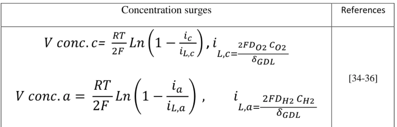
The expressions for the concentration overvoltages are summarized in Table II.2.
References Concentration surges [34-36]
=
(
) ,
(
)
Table II.2: Expressions of concentration overvoltages22
II.3 Thermodynamics of Chemical Reactions
II.3.1
Free Energy Change of Chemical Reactions
Consider the chemical reaction below;
aA+ bB → cC + dD
(II.17)The change in Gibbs function of reaction, or Gibbs free energy of the reaction, under Constant temperature and pressure, is given by the equation
∆G = c
+ d
- a
- b
(II.18)
where
µ
is the chemical potential of the species. The maximum network obtainable from a chemical reaction can be calculated by the free energy change of the chemical reaction, the free energy change of a chemical reaction is given by∆G = ∆H – T ∆S
(II.19)
II.3.2
Standard Free Energy Change of a Chemical Reaction The chemical
potential of any substance may be expressed by an equation of the form
µ = µ
o+ RT ln a
(II.20) where a is the activity of the substance andµ
has the valueµ°
when a is unity. The standard free energy change is given by=
+
−
−
(II.21) where C
o
indicates the standard chemical potential of product C, and so on. Substituting Eqs.2.48 and (II.18) into Eq.(II.21) yields
(II.22)
Hence, the standard free energy change of a chemical reaction is
(II.23)
Assuming a process at constant temperature and pressure at equilibrium , since the free energy change for this process is zero, Eq (II.23) becomes23
(II.24)
where the suffixes in the activity terms indicate the values of the activities at equilibrium, and is the equilibrium constant for the reaction.
The importance of the knowledge of is that it allows to be calculated for any composition of a reaction mixture. Knowledge of indicates whether a reaction will occur or not. If is positive, a reaction cannot occur for the assumed composition of reactants and products. If is negative, a reaction can occur. [38]
II.3.3
Relation Between Free Energy Change in a Cell Reaction and Cell
Potential
The enthalpy change of any reaction, assuming constant temperature and pressure, can be showed as follows :
(II.25)
If the reaction is carried out in a heat engine, then the only work done by the system would be the expansion work,(II.26)
Hence Eq (II.24)becomes;(II.27)
If the same reaction, which is under consideration is carried out electrochemically, the only work done by the system will not be the expansion work of the gases produced, but will also be the electrical work due to the charges being transported around the circuit between the electrodes. The maximum electrical work that can be done by the overall reaction carried out in a cell, where and are the reversible potentials at the cathode and anode respectively, is given by
(II.28)
In the cell, n electrons are involved and the cell is assumed to be reversible ( i.e., overpotential losses are assumed to be zero ). Multiplying Eq. (II.28)by the Avogadro number, N, in order to have molar quantities gives.
24
where F is the Faraday number, and
∆
Vrev is the difference between reversible electrode potentials.The only work forms assumed are the expansion work and electrical work.
(II.30)
In addition to these, assuming the process is reversible
(II.31) Substituting Eq.(II.29) – (II.31) into Eq.(II.25), the enthalpy change will be
ΔH =
(II.32)
Eq. (II.32) can be rearranged as follows,(II.33)
where
(II.34)
and
E =
(II.35)
Substituting Eqs. (II.34)and (II.33)into Eq. (II.35) gives(II.36)
E, which is defined as the difference in potentials between the electrodes is called as the electromotive force of the cell ( i.e, the reversible potential of the cell, ). If both the reactants and the products are in their standard states, Eq (II.36) can be written as(II.37) where is the standard electromotive force, or – as most commonly referred to – is the standard reversible potential of the cell.
II.3.4
Nernst Equation
Let us consider the following reaction,
25
where k moles of react with l moles of L to produce m moles of . Each of the reactants and the products have an associated activity; , and being the activity of the reactants, ; being the activity of the product. For ideal gases, activity term can be written as
(II.39) is the partial pressure of the gas, and is the pressure of the cell. Eq. (II.22)can be rearranged for the the reaction given in Eq. (II.38), as follows.
̅
̅̅̅̅ (
) (II.40)
In the Eq. (II.40), ̅ and ̅̅̅̅show the change in molar Gibbs free energy of formation, and the change in standard molar Gibbs free energy of formation. From Eq(II.36), the following relation can be written,
(II.41)
Substituting Eq. (II.41)into Eq. (II.40)gives the effect on voltage as follows,
̅̅̅̅
(
) (II.42)
Substituting Eq. (II.37)into Eq (II.42)yields,
(
)
(II.43)where is the standard electromotive force, and is defined to indicate the reversible electric voltage. Eq. (II.43)can be rewritten by substituting (II.24)and Eq(II.39), as fo llows.
(
()
( ) ( )
)
(II.44)
Eq. (II.43) and (II.44) give the electromotive force in terms of product or/and reactant activity, and is called Nernst equation. The electromotive force calculated using this equation is known as the Nernst voltage, and is the reversible cell voltage that would exist at a given temperature and pressure
26
II. 4 Water Management
The transport of water within the PEMFC is one of the most important phenomena that directly affects the behavior of the membrane (heart element of the cell). The degree of humidification of the latter is of major importance because of its influence on the efficiency and on the performance of the cell. Water management in PEMFC has become a major concern for researchers and manufacturers because it is a complex issue for which there is no single answer. Indeed, the presence of water is both necessary and harmful to the proper functioning of the cell: a good hydration of the membrane allows better proton conductivity, while too much water vapor can condense and the liquid water thus formed may prevent reagents from reaching the electrodes. To manage this paradox, it is necessary to understand where the water in the heart of the cell comes from and how it can impede its functioning.
Typically, the humidification is applied to the anode and / or cathode inputs to supply water to the membrane region. On the other hand, water is produced at the cathode / membrane interface due to the electrochemical reaction of H + / O2
Les performances de la pile peuvent être affectées par le noyage ou l’assèchement. Figure II.1: Occurrence processes in a PEM fuel cell. The PEM fuel cell is composed of (a) bipolar plate, (b) gas flow channel, (c) diffusion layer, (d) catalyst layer, and (e) polymer electrolyte layer [39]
27
II.4.1 Transfers of water in cell
The water present in the cell can have two sources: the humidification of the reactive gases and the cathodic reaction. In a PEMFC, the water is transported in the supply channels, but also through the membrane and the electrodes. We will now take a closer look at the two water transport mechanisms through the membrane shown in Figure (II.2).
Electro-osmosis
Across the membrane, the protons carry with them a number of water molecules. Measurements of the electro-osmosis coefficient (number of water molecules per proton) were carried out on membranes of Nafion117® in a liquid medium at 30 ° C. by Zadowinski et al. (1993) [18]. They observed a linear growth of the electro-osmosis coefficient as a function of the water content λ (number of water molecules per sulphonic site). The water content can be modified by heat treatment of the membrane. Without treatment, when the membrane is in contact with liquid water, λ is classically 22 and the electro-osmosis coefficient is 2.5 H2O / H +. The latter falls to 0.9 for λ equal to 11. in submerged membranes.
Measurements have also been made ( Zawodzinski et al ., 1995) [39]in more or less saturated gaseous media, the electro-osmosis coefficient is then constant and equal to 1 for a wide range of values of λ (1.4-14 ).
Diffusion
The Nafion® membrane can be approximated by a dense medium, that is to say with a compact
structure (non-porous), in which the free spaces between the molecules are of the order of magnitude of the length of the bonds (Marchand , 1998) [33].The transport in these dense
membranes is done according to 3 stages, sorption of the solute molecules on the upstream face of Figure II.2: Mechanisms of water transport in the membrane
28
the membrane, diffusion of the permeate through the membrane and desorption of the solute from the downstream face of the membrane.
The kinetically limiting step is the diffusion step. The solute diffuses from the most concentrated medium to the most dilute under the influence of a chemical potential gradient. The flow of diffusion through a dense membrane is governed by the law of Fick whose expression can be written:
J= -D
(II 45)
WithJ: molar diffusion flux
D: Coefficient of diffusion of water in the membrane, em: Thickness of the membrane,
Δ
c
: concentration difference across the membrane.With regard to the flow of water in the electrolyte of the cells, this flow generally takes place from the cathode to the anode. It is even more important that the membrane is thin and that the chemical diffusion coefficient is high.
II.4.2
Effect of operation condition in water management
To avoid of faille in FC according to the improper water management solution such as variety of operating conditions that are suggested by many authors (pressure drop, temperature gradient, control mass flow by compressor, etc.).
II.4.2.1 Humidity
To obtain high performance in FC typically gas inlets are humidified. Buechi and Srinvasan investigated that operation at humidified inlet gases are 40% greater when FC figure out without humidity. Besides, Natarajan and Nguyen declare that with the increasing of humidity at anode side to reduce water transfer due to back-diffusion, going to increase current distribution, etc. [40]
II.4.2.2 Flow rate
in 2008 investigated for air flow rate. Stated that in low flow rate it is beneficial in keeping water in dry cells but will cause of flooding. Hakenjos at al, mentioned FC performance increase (out -put current density higher) with gain flow rate due to higher stoichiometry and the water removed from the flooded cell [41]
29
II.4.2.3 Temperature
increase temperature leads to increase in saturation pressure and causes evaporation. As a Matter of fact, reduce in flooding will be happened when liquid water diminished. He et al. Investigated of while another operating condition in which (air flow, cell voltage) are constant with increasing temperature from 40 °C to 50 °C causing improvement flooding in the cell [41].
II.4.2.4 Pressure
Electro-osmotic flow rate in normal operating condition is greater than back diffusion flow rate with homogeneous pressure. Wilkinson et al. observed water produced at the cathode side absorbed by the concentration gradient to anode and cause to prevent of flooding. Elevated temperature (evaporation) and gas flow contribute (contribute dissolve water) cause to reduce flooding. However, it cannot be guaranteed drying never happen in the membrane.
II.4.3 Thermal management
Thermal management is an important role to increase/ decrease of performance of the FC.
II.4.3.1 influence of freezing
Freezing can effect on the durability of the FC via thermal and mechanical stress. Decreasing temperature causes to the reduction in proton conductivity of Nafion membrane. Most components that are influenced by freezing temperature such as backing layers, gas diffusion layer and membrane (rarely will be happened because water in membrane strong bond with captions).
II.4.3.2 Start up from freezing
When water at cathode side is not removed during start up with temperature below zero, ice will be covered in surface of GDL and cause to blocking at the catalyst layer. Finally, FC voltage drops and even shuts down FC.
II.4.3.3 Influence high temperature
Performance FC in high temperature has a few benefits such as increase electrochemical kinetics and the result enhance efficiency, advance endurance for contaminants and augments the water management and cooling system.
II.5 Conclusion
In this research work ,The PEMFC modeling and diagnosis are the most important issues treated in literature. A good diagnosis strategy contributes to improve the lifetime of the FC and then to improve the availability of the system built around it, It has been established that the FC is subject to a lot of fault during its operating. The latter are due to multi-physical phenomenon namely the temperature, the pressure and the humidity of the gas involved within the FC stack and cells. Several models have been developed to understand this phenomenon and to evaluate the FC performances according to different conditions of use but also to detect .
31
CHAPTER III
30
III.1.Introduction
In a typical PEM fuel cell microchannel, a GDL made of carbon tefloned paper or carbon fabric forms one of the walls, while the other three walls are formed or machined in a bipolar plate made of carbon or metal materials treaties.
This chapter describes a complete, stationary, monophasic model with the flow field in the whole cell of the PEM type with 2D geometry. More precisely, it is a matter of constructing a model that takes into account most of the phenomena interacting within the cell, after a presentation of the structure of the cell, the mass and heat transport equations governing the operation and the different properties of the flow are presented. Through these equations adapted to the model, a presentation of the numerical tool used CFD FLUENT is made.
III.2 Physical Model
The active physical phenomena encountered in the different zones of the stack are: The transport in the continuous and porous media which include the conservation equations (speed, heat, and mass) as well as the empirical relations, with source terms that explain the reactions electrochemical and Joule effect. To be able to build the mathematical model of a planar geometry cell, we first have to define a macroscopic geometrical image, on which we place the coordinate system and define the system of equations composing the model.
III.2.1 Geometry of the modeled structure
The different elements of the model are presented and detailed in this section. The geometry of a PEMFC model cell consists of two cathodic and anodic straight-side flow channels. These channels are separated by two diffusion layers (GDLs) inside which are the so-called active or catalytic reaction zones (CLs) located on either side of a proton exchange membrane or electrolyte, commonly called Membrane-Electrode-Assembly (MEA) as shown in (Figure III.1).
III.2.2 Model assumptions
The determination of a mathematical model of a process generally requires various simplifying assumptions in order to limit its complexity. Our model is based on the following assumptions: - The cell is powered by wet hydrogen and oxygen.
- The operating state of the cell is stationary. - The flow in the channels is considered laminar. - The fluid is incompressible.
- Monophasic model (water in vapor state).
32
Figure III.1: Presentation of different areas of study of PEMFC.
III.3 Mathematical equations
The transport of the different chemical species must be taken into account in the system of equations describing the dynamics of the fluids in the channels and the porous zones.
The model consists of a single system of nonlinear partial differential equations representing the conservation equations of mass, momentum, continuity, and energy. The conservation equations are written:
Control volume
Bipolar plate (PB)
Cathode channel (O2, H2O vapor)
Gas diffusion layer (GDL) Catalyst Layer (CL) Membrane (M)
33 Continuity equation
The transport of the different chemical species must verify the following continuity equation:
(III.1)
For all the zones of this model, the term source of mass . The porosity is equal to 1 in the channels.
Momentum equation
The fields of velocity and pressure are obtained by the resolution of the equations of motion which are written as follows:
( ) ( )
(III.2) ( ) ( )
(III.3)
The source terms SU , SV are equal to zero in all zones except for the gas diffusion layers
and the catalyst layers model the behavior of the porous medium they are based on Darcy's law.
(III.4)
(III.5) Where: ε: the porosity, K: the permeability of each porous medium of the pile, μ: the viscosity
Conservation equation of species
The transport of the different chemical species must be taken into account in the system of equations describing the dynamics of the fluids in the channels and the porous zones. The mass fractions of the different species obey an equation of the same form as the transport equation, or species conservation is necessary to calculate the mass balance for each reagent involved in this model.
( ) ( ) (III.6)
Where the index « i ».designates oxygen o2 on the cathode side and H2 hydrogen on the
34
Where and indicate respectively the effective diffusion coefficients and the molar
fractions of the species « i ».
In order to take into account the geometrical constraints of the porous media, the diffusivities are corrected by using the Bruggemann correction formula [24], [42].
(III.7)
represents the diffusion coefficients of the species « i ».as a function of temperature and
pressure is expressed by:
( )
( ) (III.8) Three species are taken into account in the calculation of source terms. These are hydrogen (H2) at the anode, oxygen (O2), and water vapor (H2Ovap) at the cathode. The source terms
SH2 and SO2 correspond to the decrease in the control volumes relative to the reaction zones
of hydrogen and oxygen. The source term of the water SH2O cathode is deduced for it from
the source terms SH2 and SO2. The variation of species across the reaction zone is dictated by
the electrochemical reaction. It is a function that depends only on the current density and is given by Faraday's law
(III.9)
Where: i is the current density in (A.cm-2), n the number of electrons exchanged during the reaction, F the Faraday constant, MI the molar mass of the constituents « i » in (kg.mol- 1). The chemical reactions of the products and reagents at the cathode and at the anode are respectively:
(III.10)
O2 +4H++4e- =H2O (III.11)
In the case of the decomposition of hydrogen at the anode, n = 2 in equation (III.10). The term hydrogen consumption is obtained with:
(III.12)
Oxygen being reduced at the cathode, n = 4 in equation (III.11) and the source term is:
(III.13)
The amount of water generated at the cathode is given by the following relation:
![Figure I.2: Operating principle of alkaline type fuel cells[2]](https://thumb-eu.123doks.com/thumbv2/123doknet/8099950.271763/16.892.306.523.892.1115/figure-i-operating-principle-alkaline-type-fuel-cells.webp)
![Figure I.3: Operating principle of solid oxide fuel cells[2]](https://thumb-eu.123doks.com/thumbv2/123doknet/8099950.271763/17.892.394.694.722.983/figure-i-operating-principle-solid-oxide-fuel-cells.webp)
![Figure I.4: Operating principle of molten carbonate fuel cells [1]](https://thumb-eu.123doks.com/thumbv2/123doknet/8099950.271763/18.892.266.552.364.689/figure-operating-principle-of-molten-carbonate-fuel-cells.webp)
![Figure I.5: Schematic of a PEM fuel cell showing the main reactions (Mattuci 2001)[1]](https://thumb-eu.123doks.com/thumbv2/123doknet/8099950.271763/19.892.251.639.101.382/figure-schematic-pem-fuel-cell-showing-reactions-mattuci.webp)
![Figure I-6: Schematic view of a PEM fuel cell and its operating principles[4].](https://thumb-eu.123doks.com/thumbv2/123doknet/8099950.271763/20.892.268.629.85.325/figure-schematic-view-pem-fuel-cell-operating-principles.webp)
![Figure I.7: The Image of fuel cell catalyst[7]](https://thumb-eu.123doks.com/thumbv2/123doknet/8099950.271763/22.892.194.621.841.1062/figure-i-image-fuel-cell-catalyst.webp)
![Figure I.8: Serpentine shaped gas flow channel configuration[20]](https://thumb-eu.123doks.com/thumbv2/123doknet/8099950.271763/24.892.305.586.290.580/figure-i-serpentine-shaped-gas-flow-channel-configuration.webp)
![Figure I.10: Spiral flow field configuration[19]](https://thumb-eu.123doks.com/thumbv2/123doknet/8099950.271763/25.892.299.576.469.751/figure-i-spiral-flow-field-configuration.webp)
![Figure II.1: Occurrence processes in a PEM fuel cell. The PEM fuel cell is composed of (a) bipolar plate, (b) gas flow channel, (c) diffusion layer, (d) catalyst layer, and (e) polymer electrolyte layer [39]](https://thumb-eu.123doks.com/thumbv2/123doknet/8099950.271763/37.892.215.668.626.920/figure-occurrence-processes-composed-bipolar-diffusion-catalyst-electrolyte.webp)
