HAL Id: hal-01652387
https://hal.archives-ouvertes.fr/hal-01652387
Submitted on 26 Oct 2020
HAL is a multi-disciplinary open access
archive for the deposit and dissemination of
sci-entific research documents, whether they are
pub-lished or not. The documents may come from
teaching and research institutions in France or
abroad, or from public or private research centers.
L’archive ouverte pluridisciplinaire HAL, est
destinée au dépôt et à la diffusion de documents
scientifiques de niveau recherche, publiés ou non,
émanant des établissements d’enseignement et de
recherche français ou étrangers, des laboratoires
publics ou privés.
The effect of weak inertia on the emptying of a tube
Alain de Ryck
To cite this version:
Alain de Ryck. The effect of weak inertia on the emptying of a tube. Physics of Fluids, American
Institute of Physics, 2002, 14 (7), pp.2102-2108. �10.1063/1.1480267�. �hal-01652387�
The effect of weak inertia on the emptying of a tube
Alain de Rycka)
E´ cole des Mines d’Albi-Carmaux, route de Teillet, 81013 Albi Cedex 09, France
共Received 26 October 2000; accepted 1 April 2002; published 21 May 2002兲
We present an extension of the classical axisymmetric Bretherton theory giving the thickness of the liquid film left on the walls of a drained tube, treating the case of weak inertia by a regular perturbation method. The results obtained by numerical integration fit Taylor’s关J. Fluid Mech. 10, 161共1961兲兴 experiments, obtained with viscous fluids 共glycerine and strong sucrose solutions兲, and Aussillous and Que´re´’s 关Phys. Fluids 12, 2367 共2000兲兴 experiments with low viscosity liquids
共hexamethyldisiloxane and water兲 when inertia becomes important. The discrepancies observed
between the theory and high Reynolds numbers experiments 共Re⬎1000兲 are commented on. © 2002 American Institute of Physics. 关DOI: 10.1063/1.1480267兴
I. INTRODUCTION
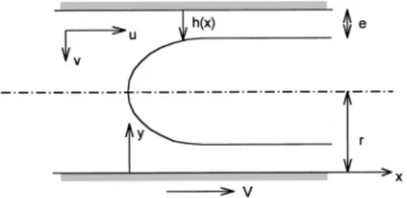
Coating flows, which are liquid flows leading to a depos-ited liquid layer on the surface of a solid, have been exten-sively studied1 for their practical importance in many tech-nologies: Painting, printing, emulsion deposition in photographic industry, air displacement in wetted porous me-dia. This last topic has received some attention for its rel-evance to oil recovery and to the understanding of air pen-etration into the lungs. An idealized situation, sketched in Fig. 1, is the emptying of a pore or a capillary filled with a wetting liquid and drained by pushing a fluid of lower vis-cosity, leading to a deposited liquid layer. The experimental work by Taylor,2 measuring the amount of several highly viscous liquids left behind when the liquid is blown out of a tube, showed a limit in liquid recovery when increasing the drainage velocity. The thickness e of the deposited film has a limiting value of approximately one third.
Bretherton3 studied, both experimentally and theoreti-cally, the drainage of a capillary at low velocity. His theory, valid when the deposited film is thin compared to the tube radius, also describes the two-dimensional共2D兲 drainage be-tween two parallel plates, and is similar to the one proposed by Landau and Levich4for plate or wire coating. In all these cases, the velocity dependence of the deposited film thick-ness is written
e⫽1.34⫺1Ca2/3, 共1兲
where Ca⫽V/␥ is the capillary number, which compares the viscous and capillary forces 共 and␥ are, respectively, the viscosity and surface tension of the liquid and V is the drainage velocity兲. is the difference of curvature between the static meniscus 共weakly deformed at low velocity兲 and the thin film. For a tube of radius r, a Hele–Shaw cell of spacing r, or a fiber of radius r, we have⫺1⫽r. For a plate withdrawn out of a liquid bath, ⫺1⫽
冑
␥/2g, where isthe specific density of the fluid. The numerical constant is obtained by matching the curvature of the meniscus with the asymptotic curvature of the thin film.3,4
At higher velocity, some discrepancies are observed be-tween Eq.共1兲 and experimental results. For plate coating, the drainage by gravity of the film becomes non-negligible. For the tube 共respectively wire兲 coating, a first semiempirical correction, proposed by White and Tallmadge for wire coating,5 is to write ⫺1⫽r⫺e 共respectively, r⫹e兲. This extends the validity of the theoretical Bretherton law to situ-ations in which the thickness of the remaining film becomes comparable with the capillary radius. In the tube case, a lim-iting value at high capillary numbers is then found: e/r
→1, quite different from Taylor’s observations:2e/r→0.34.
To go to higher velocities, Cox6proposed a theory giv-ing the amount of liquid left on the walls of the tube based on an exponential shape for the driving bubble but the fit with the Taylor’s results is not so good. The two-dimensional finite element calculation with a free interface by Reinelt and Saffman,7leads to a very good agreement with these experi-mental results, but does not take into account inertia. But, for liquids of low viscosity like water or ethanol, encountered in washing processes for example, the liquid inertia leads to a noticeable thickening of the remaining film, for drainage at capillary numbers smaller than unity.8
Giavedoni and Saita9 presented numerical results, both in the axisymmetric and plane cases, obtained by a boundary integral method.10Their work included the inertial forces and they found a thinning effect due to inertia for Reynolds num-bers up to 70. This work has been recently completed by Heil11in the 2D-channel case using a finite element method. It demonstrates a small thickening effect due to inertia for higher Reynolds numbers up to 280.
Here, we propose an extension of the Bretherton’s clas-sical axisymmetric analysis to include weak fluid inertia ef-fects. This study is an alternative of the Giavedoni and Saita9 and Heil11 works. Its numerical part is reduced to the reso-lution of a third-order ordinary differential equation,12,13and is inspired by previous theoretical work introducing weak fluid inertia in plate14 –16 and wire coating,17,18 and by 2D
a兲Electronic mail: deryck@enstimac.fr
2102
channel drainage.19 In the latter case, the theory takes also into account the drainage by gravity.
After the presentation of the equations describing the drainage of a cylinder in Sec. II, they are solved at leading order in Sec. III using the lubrication approximation. In Sec. IV, a first-order approximation is used, introducing the iner-tial terms. Two cases are then studied: Highly viscous liquids and liquids of low viscosity. The results obtained are com-pared, respectively, with the Taylor’s experiments2 and the recent ones by Aussillous and Que´re´.8
II. DESCRIPTION OF THE PROBLEM
We consider an infinite tube of circular geometry共radius r兲, full of liquid and drained by air at a constant velocity V. In a frame attached to the air bubble, we define the axial origin and direction x from the apex to the air side. The radial direction y is chosen from the tube wall inwards. In these coordinates, the axial and radial liquid velocities are u andv. In this frame, the walls of the tube have velocity V.
The profile of the film surrounding the bubble is h(x), de-creasing from r to the constant value e for x ranging from 0 to infinity.
The steady-state Navier–Stokes equations in these coor-dinates are written3
再
2u x2⫹ 2u y2⫹ 1 r⫺y u r冎
⫽ p x⫹冉
v u y⫹u u x冊
共2兲 and 再
2v x2⫹ 2v y2⫺ 1 r⫺y v y⫺ 1 共r⫺y兲2v冎
⫽p y⫹冉
u v y⫹u v x冊
, 共3兲where and are, respectively, the viscosity and specific mass of the liquid, and p the pressure. The liquid is incom-pressible, so we have v y⫺ v r⫺y ⫹ u x⫽0. 共4兲
The boundary conditions at the walls are
for y⫽0, u⫽V and v⫽0. 共5兲
On the air–liquid interface, y⫽h(x), neglecting the gas vis-cosity, the stresses are due to the interface curvature and are written
psnគ ⫺=snគ ⫽ponគ ⫺␥cnគ , 共6兲
where ␥ is the surface tension of the liquid and po the air
pressure. The subscript s means that the value is taken at the liquid–gas interface. The vector nគ is normal to the surface and= the viscous stress tensor. They are written
nគ ⫽ 1
冑
1⫹hx2冉
1 ⫺hx冊
and = ⫽冉
2v y ⫺ u y⫺ v x ⫺uy⫺vx 2u x冊
, 共7兲where the subscript x means differentiation with respect to the axial coordinate. The curvature c is given by
c⫽ hxx 共1⫹hx 2兲3/2⫹ 1 共r⫺h兲
冑
1⫹hx 2. 共8兲III. LEADING ORDER SOLUTION
Assuming the slope of the thin film to be small and radial velocity to be much smaller than the axial velocity, the radial component of the Navier–Stokes equation共3兲 reduces to p/y⫽0. The pressure is then uniform in the thin film and is written, using the radial projection of Eq.共4兲
p⫽ps⫽po⫺␥c, with c⫽hxx⫹ 1
r⫺h. 共9兲
Equation共6兲, in the axial direction yields u
y
冏
s⫽0. 共10兲Finally, Eq. 共2兲, the axial component of the Navier–Stokes equation, reduces to y
冉
共r⫺y兲 u y冊
⫽ 1 px共r⫺y兲, 共11兲may be integrated twice to give the velocity profile
u⫽V⫹1 px
冉
共r⫺y兲2 4 ⫺ r2 4⫺ 共r⫺h兲2 2 ln r⫺y r冊
. 共12兲 A last integration gives the flux Q, which is a constant in steady-state regime. Its value is related to the thickness e of the deposited film byQ⫽
冕
h r 2y u d y⫽冕
e r 2y V d y . 共13兲 Introducing Eq. 共12兲 into Eq. 共13兲 leads toFIG. 1. Sketch of a tube full of liquid and drained by an air bubble.
2103 Phys. Fluids, Vol. 14, No. 7, July 2002 The effect of weak inertia
共r⫺h兲2⫺共r⫺e兲2 ⫽Ca1 cx
冉
r4 8⫺ r2共r⫺h兲2 2 ⫹ 3 8共r⫺h兲 4 ⫹共r⫺h兲 4 2 ln r⫺h r冊
. 共14兲Finally, since the normalized thickness E⫽e/r, ratio be-tween the thickness of the deposited film and the tube radius, remains a small parameter, we have truncated Eq.共14兲 to the two first terms of its Taylor expansion close to E⫽0. It then reduces to YXXX⫽3 1⫺Y Y3
冉
1⫹E Y⫺1 2冊
⫺ E2 Ca2/3YX, 共15兲 when using the same reduced variables as those used by Bretherton:3A film thickness scaled by e, the thickness of the film at infinity (h⫽eY), and an axial coordinate scaled by a length ᐉ, where ᐉ⫽eCa⫺1/3(x⫽ᐉX).We then obtain a generalized version of the Landau–Levich3,4 equation with the additional terms in E coming from the cylindrical geometry: The first from the expression of the flux, the second from the radial curvature.
A. Numerical integration
Since the profile does not depend explicitly on x, we use the thickness y as the variable of integration and integrate numerically a second order differential equation for G(Y )
⫽YX. This method leads to more stability in the numerical
integration 共we have used a commercial code—ode45 rou-tine from Matlab—based on a 4 to 5 Runge–Kutta method20兲, but does not allow to find a nonmonotonous pro-file since by construction, we impose a univocal relation be-tween y and its derivative yx.
The integration is started close to the thin film using the linearized conditions:3,13 Yo⫽1⫹esX, Yo
⬘
⫽sesX and Y o
⬙
⫽s2esX, where⑀⫽esX is a small quantity 共10⫺4in our
cal-culations兲 and where s is solution of the following equation obtained by linearization of Eq.共15兲:
s3⫹ E
2
Ca2/3s⫹3⫽0. 共16兲
The initial conditions for G then is written
G共1⫹⑀兲⫽s⑀, and dG
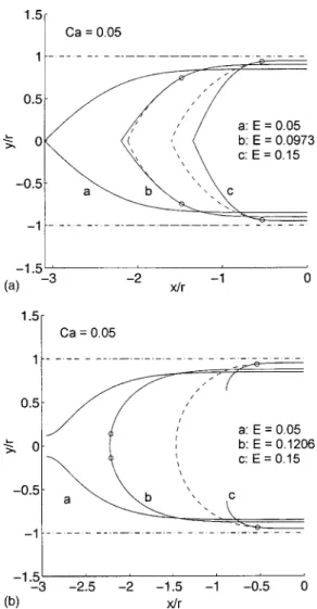
dY共1⫹⑀兲⫽s. 共17兲 For a given Ca and E, we integrate G from Y⫽1⫹⑀to 1/E. Figure 2共a兲 shows several bubble profiles obtained for Ca
⫽0.05.
We observe that there is a critical thickness y at which a matching to a sphere is possible, i.e., there exists a point on the profile 共small circles in Fig. 2兲 where the two radii of curvature are equal
YXX⫽
E Ca2/3
1
1⫺EY. 共18兲
With this matching, we insure that the profile ends with a static zone where the pressure is constant. This matching is represented in Fig. 2共a兲. The profiles are matched at the circle point with a curve solution of hzz⫽⫺1/(r⫺h) 共dotted lines兲. E⫽0.0973 is the highest value allowing a matching at Ca⫽0.05. There is no matching feasible for E⫽0.05 for this value of the capillary number.
B. Results
In Fig. 3, we have compared this maximum matching thickness共dotted line兲 with the experimental values obtained by Taylor 共denoted by squares兲. In the same figure, these results are also compared to the asymptotic matching by Bretherton 关Eq. 共1兲, dashed and dotted line兴. Both are only valid for very small capillary numbers, but the denominator in Eq.共18兲 ensures a saturation effect.
In order to improve the accuracy, we used the full ex-pression of the curvature. The film profile is then given by
CX⫽3
1⫺Y Y3
冉
1⫹EY⫺1
2
冊
, 共19兲FIG. 2. 共a兲 Approximate curvature. Bubble profile for Ca⫽0.05 and E
⫽0.05, 0.0973, and 0.15. Dash and dotted lines: Walls of the tube. Dashed
lines: approximated spheres (yxx⫽⫺1/(r⫺y)). Circles: matching points;
there is no matching for E⬎0.0973. 共b兲 Exact curvature. Bubble profile for Ca⫽0.05 and E⫽0.05, 0.1206, and 0.15.
where C is the normalized curvature C⫽ YXX 共1⫹Ca2/3Y X 2兲3/2⫹ E Ca2/3 1 共1⫺EY 兲共1⫹Ca2/3Y X 2兲1/2. 共20兲
With this correction, we obtain more realistic bubble profiles, as shown in Fig. 2共b兲. As previously, for each capillary num-ber, a maximum thickness allowing matching is found. This value fits the experimental data well for capillary numbers up to 0.25 as can be observed in Fig. 3 共solid line兲. Neverthe-less, we still observe some discrepancies for higher capillary numbers which here do not come from inertia since, in the Taylor’s experiments, the Reynolds numbers (Re⫽Vr/) were always lower than unity.
IV. FIRST-ORDER SOLUTION
To achieve a more accurate solution when the thickness of the deposited film increases, we need to obtain the first-order correction the leading first-order result described in the pre-vious section. Up to the first order in Ca1/3, the terms previ-ously neglected have been written using the expressions of the velocity obtained at the zeroth order.
To first order, the pressure at the liquid–bubble interface is written
ps⫽⫺␥c⫹2vo y
冏
s
, 共21兲
where the subscript o means that the velocity is computed at the zeroth order. Using the incompressibility of the liquid
关Eq. 共4兲兴 leads to ps⫽⫺␥c⫺2 uo x
冏
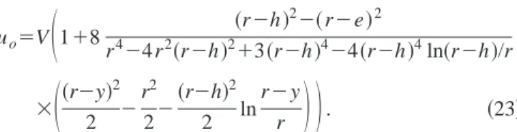
s⫺2 uos h hx, 共22兲where uo is given by Eqs.共12兲 and 共13兲
uo⫽V
冉
1⫹8 共r⫺h兲2⫺共r⫺e兲2 r4⫺4r2共r⫺h兲2⫹3共r⫺h兲4⫺4共r⫺h兲4ln共r⫺h兲/r ⫻冉
共r⫺y兲 2 2 ⫺ r2 2⫺ 共r⫺h兲2 2 ln r⫺y r冊冊
. 共23兲The pressure profile inside the thin film is given by Eq.共3兲 at first order:
再
y冉
⫺uox
冊冎
⫽ py, 共24兲
and leads together with Eq. 共22兲 to p⫽⫺␥c⫺uo x
冏
s⫺ uo x ⫹2 uos r⫺hhx. 共25兲 At this same order, Eq. 共2兲 is written
再
r⫺y1 y冉
共r⫺y兲wy冊冎
⫽px⫹冉
vo uo y ⫹uo uo x冊
. 共26兲The last step is to integrate this equation three times in order to obtain the flux as in the previous section and then to expand the expression versus E. We obtain finally in the reduced Landau–Bretherton coordinates
CX⫽3 1⫺Y Y3
冉
1⫹E Y⫺1 2冊
⫹3 Ca2/3 Y3再
YXXY冋
43⫺7Y 40 ⫹E⫺129⫹270Y⫺61Y 2 240册
⫹YX 2冋
⫺41⫺2Y 20 ⫹E 41⫺39Y⫺2Y2 40册冎
⫹351 FECa4/3YX Y3冋
6共⫺9⫹Y⫹Y 2兲 ⫹E1728⫺1131Y⫺171Y 2⫹134Y3 32册
, 共27兲where C is still the reduced curvature given by Eq. 共20兲. F
⫽␥r/2⫽Re/Ca is a nondimensional number which de-pends only on the nature of the liquid and of the radius of the tube. For water in a tube of radius 1 mm, F⫽72 000. For glycerol in the same tube, F⫽0.36.
In Eq. 共27兲, two new terms appears, compared to Eq.
共19兲, both expanded in powers of E. The first one is a
cor-rection to the lubrication approximation. After Bretherton, Spiers et al.21introduced this correction in the case of plate coating. The second one is an inertial correction. First intro-duced by Esmail and Hummel14 for the plate coating prob-lem, this inertial term has been shown to lead to a thickening of the film entrained by a plate16or a fiber withdrawn from of a liquid bath.18
Together with Eq. 共20兲, Eq. 共27兲 leads again to a third ordinary differential equation for the film profile. The nu-merical integration still starts from a point close to the thin film: Y⫽1⫹esX, where s is obtained by the linearization of
the system. With the new terms, Eq. 共16兲 is replaced by
FIG. 3. Thickness of the deposited film scaled by r vs the capillary number. Dashed and dotted line: Eq.共1兲. Dashed line: Maximum thickness allowing a matching with a spherical cap using an approximated curvature. Solid line: the same, but using an exact curvature expression. Squares: Taylor’s experi-ments共Ref. 2兲.
2105
s3⫹ E 2 Ca2/3 s 共1⫺E兲2⫹3⫺Ca2/3s2
冉
27 10⫹E冊
⫹FECa4/3s冉
6 5⫺ E 2冊
⫽0. 共28兲The final step is the same as previously. For a given param-eter number F, we search, for each value of the capillary number Ca, the maximum value of the reduced film thick-ness E allowing a matching of the film profile with a spheri-cal cap. This has been done in two cases. First, with F⫽0, for liquids of high viscosity, and then for parameter numbers higher than 10 000, representative of liquids of low viscosity.
A. Highly viscous liquids
For highly viscous liquids, the inertial correction re-mains negligible for capillary number less than unity, as is the case of the experiments by Taylor.2 Figure 4 compares them with the maximum thickness allowing a bubble profile ending with a spherical cap with F⫽0. The agreement is quite good. In Fig. 5, several bubble shapes obtained for Ca ranging from 0.001 to 1 are compared. The matching points,
not shown, are close to the axis of revolution except for Ca⫽1. In that latter case, the matching occurs at half the bubble size. In all cases we observe that the bubbles are only slightly deformed: the thin film of constant thickness is at-tained above a distance x from the top of the cap close to (r⫺e).
B. For liquids of low viscosity
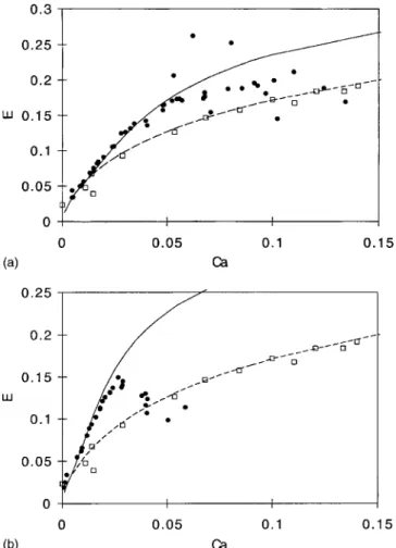
Finally, the system of equations has been integrated us-ing as parameter F⫽19 330 and 67 670, values representa-tive of a low viscosity silicone oil drained out of a tube of radius 0.4 and 1.4 mm. The maximum thickness curves are compared in Fig. 6 with the Aussillous and Que´re´ experiments.8
We observe that the threshold and the beginning of thickening due to inertia are well represented by the theory. Nevertheless, for higher capillary numbers, the theory over-estimates the experimental values obtained. Several hypoth-eses may be put forward to explain this discrepancy. First,
FIG. 4. Taylor’s experiments共Ref. 2兲 and the maximum value of E allowing a bubble profile ending like a sphere for F⫽0.
FIG. 5. From left to right: bubble shapes for Ca⫽0.001; 0.01; 0.1, and 1. Dash and dotted lines: Positions of the walls.
FIG. 6. 共a兲 Experimental deposited film thicknesses and the theoretical maximum ones allowing a matching with a spherical cap. Black points: Experiments with hexamethyldisiloxane共Ref. 8兲 共⫽0.76 kg/m3,⫽0.5 cP and␥⫽15.9 mN/m兲 and a tube of radius 0.4 mm (F⫽19 330). Solid line: Theory with the same parameter. White points: Taylor’s experiments共Ref. 2兲. Dashed line: Theory with F⫽0. 共b兲 Experimental deposited film thick-nesses and the theoretical maximum ones allowing a matching with a spheri-cal cap. Black points: Experiments with hexamethyldisiloxane共Ref. 8兲 and a tube of radius 1.4 mm (F⫽67 670). Solid line: Theory with the same parameter. White points: Taylor’s experiments共Ref. 2兲. Dashed line: Theory with F⫽0.
the theory presented here includes inertia as a first order perturbation and therefore has no reason to describe high inertia situations. Secondly, the method used computes only steady-state axisymmetric bubble profiles, with no oscilla-tions of the film thickness and of maximum thickness for a given capillary number. This solution is perhaps not the most stable at high velocity. In particular, further work should be made to check if the maximum thickness criterion leads, at high velocity, to the less dissipative solution.
Finally, there are some limitations to this visco-inertial regime in the Aussillous and Que´re´’s experiments.8 As de-scribed by the authors, the finite length of the liquid reservoir leads to a deposited film thickness limited by the viscous boundary layer. Another point is that the steady-state visco-inertial regime is not reached in these experiments, which were performed with an air–liquid front displacement of about 20 cm. But it can be observed in the simulations that the size of the transition zone between the apex and the thin
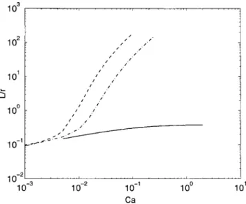
film, given by L⫽ᐉ/s becomes very large compared to the tube radius r at high Reynolds numbers. As an example, we have plotted on Fig. 7 the profiles obtained for F⫽67 670. We observe that, contrary to the F⫽0 case 共Fig. 5兲, the bubble is highly deformed for Ca⭓0.01. In Fig. 8, we have plotted this length L of the transition zone, scaled by r, ver-sus the capillary number. We observe that as long as inertia remains negligible, the bubble length is small compared to its width. But when inertia becomes important 共Re⬎1000兲, the bubble length grows and may reach about 10 cm.
V. CONCLUDING REMARKS
We presented an extension of the classical axisymmetric Bretherton theory, including weak inertial effects, based on a regular perturbation method. By numerical integration of the film profile and looking for the maximum value of the de-posited film thickness allowing a matching with a spherical cap, a velocity dependence of this thickness is obtained and, for liquids of low viscosity, a thickening due to inertia is observed. The agreement between these numerical results and the experimental results up to moderate Reynolds num-bers共Re⬍1000兲 is quite good. This thickening is not what is reported by Giavedoni and Saita.9 They report a slight thning due to inertia for Reynolds numbers up to 70. We in-deed retrieve this result when looking at low Reynolds or F numbers, as shown on Fig. 9 where E, the film thickness scaled by r, is plotted versus the number F for different capillary numbers. In particular, it can be noticed that this thinning, which may attain 20% for Ca⫽1, is maximum for Re around 100. This could explain why the last experimental points by Taylor are slightly under the theoretical curve in Fig. 4. The values of F for the experiments he performed at a capillary number greater than one may be evaluated at around 0.5共glycerol and tube radius of 1.5 mm兲. In Fig. 9, it can be seen that this leads to a correction of 6% for Ca⫽1. Finally, some points remain to be investigated. The thickness numerically obtained is a maximum thickness and it is not clear why it is this thickness which gives good correspondence with the experimental values.
FIG. 7. From left to right: bubble shapes for F⫽67 670 and Ca⫽0.001, 0.01, 0.1, and 1.
FIG. 8. Size of the transition zone scaled by r vs Ca. Black line: F⫽0. Dashed and dotted line: F⫽19 330. Dashed line: F⫽67 670.
FIG. 9. Maximum deposited thickness共scaled by r兲 E vs F for three capil-lary numbers. The circles indicates Re⫽1000.
2107
Another remaining issue is the description of the rapid draining of capillaries, for Reynolds numbers higher than 1000. For the present problem, a finite Reynolds numbers theory, like the numerical theory by Heil,11is necessary. ACKNOWLEDGMENTS
It is a pleasure to thank Pascale Aussillous and David Que´re´ for fruitful discussions.
1
K. J. Ruschak, ‘‘Coating flows,’’ Annu. Rev. Fluid Mech. 17, 65共1985兲.
2
G. I. Taylor, ‘‘Deposition of a viscous fluid on the wall of a tube,’’ J. Fluid Mech. 10, 161共1961兲.
3F. P. Bretherton, ‘‘The motion of long bubbles in tubes,’’ J. Fluid Mech.
10, 166共1961兲.
4
L. D. Landau and B. Levich, ‘‘Dragging of a liquid by a moving plate,’’ Acta Physicochim. USSR 17, 42共1942兲; also in V. G. Levich, Physical
Hydrodynamics共Prentice-Hall, Englewood Cliffs, 1962兲.
5D. A. White and J. A. Tallmadge, ‘‘A theory of withdrawal of cylinders
from liquid baths,’’ AIChE J. 12, 333共1966兲.
6
B. G. Cox, ‘‘On driving a viscous fluid out of a tube,’’ J. Fluid Mech. 14, 81共1962兲.
7D. A. Reinelt and P. G. Saffman, ‘‘The penetration of a finger into a
viscous fluid in a channel and tube,’’ SIAM共Soc. Ind. Appl. Math.兲 J. Sci. Stat. Comput. 6, 542共1985兲.
8P. Aussillous and D. Que´re´, ‘‘Quick deposition of a fluid on the wall of a
tube,’’ Phys. Fluids 12, 2367共2000兲.
9M. D. Giavedoni and F. A. Saita, ‘‘The axisymmetric and plane cases of
gas phase steadily displacing a Newtonian liquid—A simultaneous solu-tion of the governing equasolu-tions,’’ Phys. Fluids 9, 2420共1997兲.
10M. J. Martinez and K. S. Udell, ‘‘Axisymmetric creeping motion of drops
through circular tubes,’’ J. Fluid Mech. 210, 565共1990兲.
11M. Heil, ‘‘Finite Reynolds number effects in the Bretherton problem,’’
Phys. Fluids 13, 2517共2001兲.
12
B. G. Higgins, W. J. Silliman, R. A. Brown, and L. E. Scriven, ‘‘Theory of meniscus shape in film flows. A synthesis,’’ Ind. Eng. Chem. Fundam. 16, 393共1977兲.
13
E. O. Tuck and L. W. Schwartz, ‘‘A numerical and asymptotic study of some third-order ordinary differential equations relevant to draining and coating flows,’’ SIAM Rev. 32, 453共1990兲.
14
A. J. Soroka and J. A. Tallmadge, ‘‘A test of the inertial theory for plate withdrawal,’’ AIChE J. 17, 505共1971兲.
15M. N. Esmail and R. L. Hummel, ‘‘Nonlinear theory of free coating onto
a vertical surface,’’ AIChE J. 21, 958共1975兲.
16A. de Ryck and D. Que´re´, ‘‘Gravity and inertia effects in plate coating,’’ J.
Colloid Interface Sci. 203, 278共1998兲.
17
A. Koulago, D. Que´re´, A. de Ryck, and V. Shkadov, ‘‘Film entrained by a fiber quickly drawn out of a liquid bath,’’ Phys. Fluids 7, 1221共1995兲.
18A. de Ryck and D. Que´re´, ‘‘Inertial coating of a fibre,’’ J. Fluid Mech. 311,
219共1996兲.
19G. C. Gardner and G. A. Adebiyi, ‘‘The liquid film left behind a large
bubble in a sloping channel,’’ Chem. Eng. Sci. 29, 461共1974兲.
20
J. R. Dormand and P. J. Prince, ‘‘A family of embedded Runge–Kutta formulae,’’ J. Comput. Appl. Math. 6, 19共1980兲.
21R. P. Spiers, C. V. Subbaraman, and W. L. Wilkinson, ‘‘Free coating of a
Newtonian liquid onto a vertical surface,’’ Chem. Eng. Sci. 29, 389