THÈSE
THÈSE
En vue de l’obtention du
DOCTORAT DE L’UNIVERSITÉ DE TOULOUSE
Délivré par : Université Toulouse 3 Paul Sabatier (UT3 Paul Sabatier) Cotutelle internationale avec : Universidad Autónoma de Nuevo LeónPrésentée et soutenue le 31/10/2018 par : Ana María HERNÁNDEZ LÓPEZ
Propriétés structurales, microstucturales et électriques du titanate de baryum dopé à l’yttrium pour l’élaboration des condensateurs
multicouches
JURY
Jacques NOUDEM, Professeur à l’Université de Caen Normandie, Rapporteur Félix SÁNCHEZ DE JÉSUS, Professeur à l’Universidad Autónoma del Estado de Hidalgo, Rapporteur Ana María BOLARÍN MIRÓ, Professeur à l’Universidad Autónoma del Estado de Hidalgo, Examinatrice Roman Jabir NAVA QUINTERO, Ingénieur de Recherche, KEMET México, Examinateur
Bernard DURAND, Professeur à l’Université Paul Sabatier, Encadrant Zarel VALDEZ NAVA, Chargé de Recherche au CNRS, Encadrant Sophie GUILLEMET-FRITSCH, Directrice de Recherche au CNRS, Directrice Juan Antonio AGUILAR GARIB, Professeur à l’Universidad Autónoma de Nuevo León, Directeur
École doctorale et spécialité :
ACKNOWLEDGMENTS
This thesis work was developed thanks to the support of the Postgraduate Cooperation Program (PCP-RU2I) Mexico-France, Project 229286, between the National Council of Science and Technology (CONACyT) and the Ministries of Foreign Affairs of Higher Education for the French Republic, with the participation of Kemet de México and Marion Technologies (France). I thank to the CONACyT for having awarded me the doctoral grant (number 516106) and thus promote my postgraduate studies.
I feel really fortunate for having the chance of taking the best of Mexico and France to grow at a personal and professional level. I thank to the Universidad Autónoma de Nuevo León and to the Université Toulouse III – Paul Sabatier for the honor of being PhD student in them, as well as for the support for the progress of this cotutelle.
My deepest and more sincere gratitude goes to my supervisors, Sophie GUILLEMET-FRITSCH, Juan Antonio AGUILAR GARIB, Zarel VALDEZ NAVA y Bernard DURAND; all of you have left in me a mark. Thanks for having opened me the doors and for trust in me to face this important challenge, guiding me with such patience and caring all these years. Thank you very much for giving so much of you to my education, for your time and availability and, most of all, for supporting and encouraging me to keep growing and giving the best of me always. I’ll keep the best memories of the long discussions and the advantage of listen and having different points of view, being able to go farther.
To Christophe TENAILLEAU and Pascal DUFOUR, thank you so much for your support, for share your experience and knowledge with me in such valuable discussions giving me the opportunity to learn a lot from you. Thanks for your advices and guidance during this period. To Edgar REYES MELO, thanks for your availability to participate in academic discussions and contributing with interesting ideas.
To Félix SÁNCHEZ DE JESÚS, Ana María BOLARÍN MIRÓ and Jacques NOUDEM for having evaluated my thesis and grant me the honor of being part of the jury.
A big thanks to the company Kemet de México, starting with the Director of Manufacturing Operations of Cards Ariel GOVEA FLORES and the team formed by Román NAVA QUINTERO, Víctor HERNÁNDEZ and Julio PÉREZ, who since the beginning offered me their support and also in a technical way and through interesting discussions contributed greatly to this research. Special thanks to Román NAVA QUINTERO for agreeing to be part of the jury, for his availability and for sharing his experience with me.
To Joseph SARRIAS, thank you for your kindness and willingness so that through Marion Technologies it would be possible to obtain crucial results for the discussions presented in this thesis.
success and wellness. Thanks also for the constant effort so that this cotutelle had the bases to be built and finished.
To Jorge Luis MENCHACA ARREDONDO my most sincere and immense gratitude, five years ago I found a great teacher and friend on my way. Thank you for believing in me, for opening doors to huge opportunities and encouraging me to be always braver. Thank you so much for having ventured to support me in this life project.
I was fortunate to work in CIRIMAT and LAPLACE laboratories at the University of Toulouse III - Paul Sabatier. In them I could experiment, learn, advance and share with people whose experience contributed to my training. My thanks to all those who work in them, as well as to my fellow doctoral students and post-doctoral students who made my stays in this university more enjoyable and with whom I was able to discuss and share ideas on multiple occasions. Special thanks to Jean-Jacques DEMAI, Marie-Claire BARTHELEMY, Benjamin DUPLOYER and Sorin DINCULESCU for their technical support in carrying out my experiments. With great appreciation I also thank Ly, Nahum, Abdé, Romain, Precious, Simo, Guillaume, Cédric, Cyril, Mateusz and Trong for their company, for the shared coffees with such interesting talks, for their support in difficult times and for the laughs.
Thanks also to my teachers at the CICFIM for contributing with their knowledge to my training.
A deep gratitude to those who gave me their friendship and support during these years in Monterrey: Monica, Roberto, Liz, Juan, Maricela, Armando, Jeane, Marco, Fernando, Oswaldo, David and Abraham, I am fortunate to have so much love from your part, thank you for so many beautiful moments, for your hugs and smiles.
Amanda, thank you for having entered with such joy in my life and allowing yourself to be part of yours, thanks for so much love and that energy that illuminates more than you imagine. I’ll always remember your words accompanied by a great and warm smile.
Codorniz, thank you for welcoming me into your home and sharing that special family with me, for the hugs and comforting words, for so many laughs, for being unconditional and not leave me alone.
To all those who despite the distance have always been with me, Papitas, Pardito, Diani, Flaquito, Cesitar, Carlitos, Lau, David, Felix, Karencita, Jenn, thank you for this great friendship that has seen us grow and make our dreams become a reality, all of you are always in my heart. Thanks also to Carlitos Franco, Wilmer, Ale, Daniel and John for accompanying me in different ways with their friendship and support on this path. I will always thank the life that during these years has given me the great gift of enlarging my family. For their immense and unconditional support, the strength they give me, so much love and joy, to help me make
MariaJo, deserve my infinite thanks for allowing me to write these words today, I owe you a great part of this
achievement.
In my beloved Colombia you will always find an immense part of who I am, of my heart: my beautiful family. How to thank for so much love? To my grandmother, my aunts and uncles, my cousins, my nephews,
Yaneth and Yas: it is you who appear daily in my thoughts, thank you for enlightening my life with your
existence, thank you for supporting me and always believing in my. Thank you for giving so much of you for my happiness, for encouraging me to always dream big and to receive me with open arms every time and no matter what. I love you immensely.
To the love of my life, who does not allow a single day to pass without me having a reason to fall in love more and being even happier. My life with you is the light in my eyes, my dreams at your side only become bigger and the world for me is better since you and I are walking hand in hand. It is for you Rho and for everything that awaits us, always together.
To those who have given their all to make my wings bigger and bigger: my parents. Thank you for supporting my decisions and giving me strength when I doubt them. Thank you for always being by my side and believing enough in me to make sense of all these years away from you. Thank you for showing me your love in so many ways, for taking care of me and taking care of my little dog angels that I miss so much. I always carry them with me, every step I have taken and I will give, has your legacy.
Contents
General Introduction ... 17
Chapter 1 ... 21
Introduction ... 21
1.1. Ceramics ... 21
1.2. BaTiO
3– Structural characteristics ... 22
1.3. Role of the dopants on the electrical properties of BaTiO3 ... 23
1.4. Role of Y2O3 ... 31
1.5. Sintering atmosphere influence over dopant occupancy in BT-doped ceramics ... 33
1.6. Multilayer ceramic capacitors (MLCCs) ... 35
References ... 40
Chapter 2 ... 49
Introduction ... 49
2.1. Electrical characterization of multilayer ceramic capacitors ... 49
2.1.1. Multilayer ceramic capacitors (MLCCs) samples description ... 49
2.1.2. Electrical characterization tests ... 50
2.1. Powders characterization ... 56
2.1.1. X-Ray Diffraction ... 57
2.1.2. Induced coupled plasma atomic emission spectroscopy ... 58
2.1.3. Scanning electron microscopy ... 59
2.2. Manufacture and characterization of ceramics ... 59
2.2.1. Raw materials description ... 59
2.2.2. Powders doping procedure ... 61
2.2.3. Green ceramics manufacturing ... 62
2.2.4. Ceramics sintering ... 63
2.2.5. Thermal treatment of powders ... 65
References ... 66
Chapter 3: Electrical characterization of MLCCs ... 67
Introduction ... 67
3.1. High Accelerated Life Tests ... 69
3.1.1. High Accelerated Life Test (HALT) – standard conditions ... 71
3.1.2. Impact of temperature on breakdown of MLCCs ... 73
3.1.3. Determination of Time to Failure (TTF) and Mean Time to Failure (MTTF) ... 75
3.2. The Weibull distribution ... 81
3.2.1. Weibull analysis – Group A ... 84
3.2.2. Weibull analysis – Group B ... 88
3.2.3. Weibull analyses – Group C ... 91
3.3. Arrhenius model applied to the analysis of combined stress (V, T) effect over
MLCCs life. ... 94
References ... 103
Chapter 4: Y
2O
3-Doping of BaTiO
3... 107
Introduction ... 107
4.1. BaTiO
3raw
powders ... 109
4.2. BaTiO3 powders thermal treatment and characterization ... 111
4.3. BaTiO3 ceramics characterization ... 117
4.3.1. BaTiO3 ceramics sintered in air ... 118
4.3.2. BaTiO3 ceramics sintered in reducing atmosphere ... 123
4.3.2.1. BaTiO3 ceramics issued from BT-A powders with Y2O3 content from 0 to 20 wt%. ... 124
4.3.2.2. BaTiO3 ceramics issued from BT-B powders with Y2O3 content from 1 to 20 wt%. ... 132
4.3.2.3. BaTiO3 ceramics issued from BT-C powders with Y2O3 content: 1 to 2 wt%. ... 140
References ... 149
General Conclusion and Perspectives ... 153
Figure Index
Figure 1.1. Scheme of the BaTiO3 perovskite structure. A) Cubic lattice (above Curie temperature, 120°C). B) Tetragonal lattice (below Curie temperature, 120°C). (Richerson,2005). ... 23
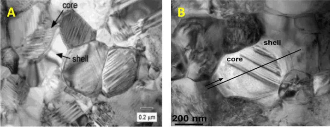
Figure 1.2. Transmission electron micrographs of core-shell structures in doped BT ceramics. (A) TEM bright field image of a X7R-type BaTiO3 ceramics by Grogger, Hofer, Warbichler, Feltz, & Ottlinger, (1998). (B) TEM of a typical core-shell grain in a BT specimen doped with yttrium and magnesium by Kim et al., (2008). ... 25
Figure 1.3. (a) Glassy second phase at triple-grain junction with selected area diffraction patterns of BaTiO3 grain inset (BF image), (b) high-resolution image of BaTiO3-glass interface showing an amorphous nature, and (c) energy-dispersive X-ray spectroscopy spectra for triple junction and BaTiO3 grain (Bo) (TEM) (Wu et al., 2007). ... 26
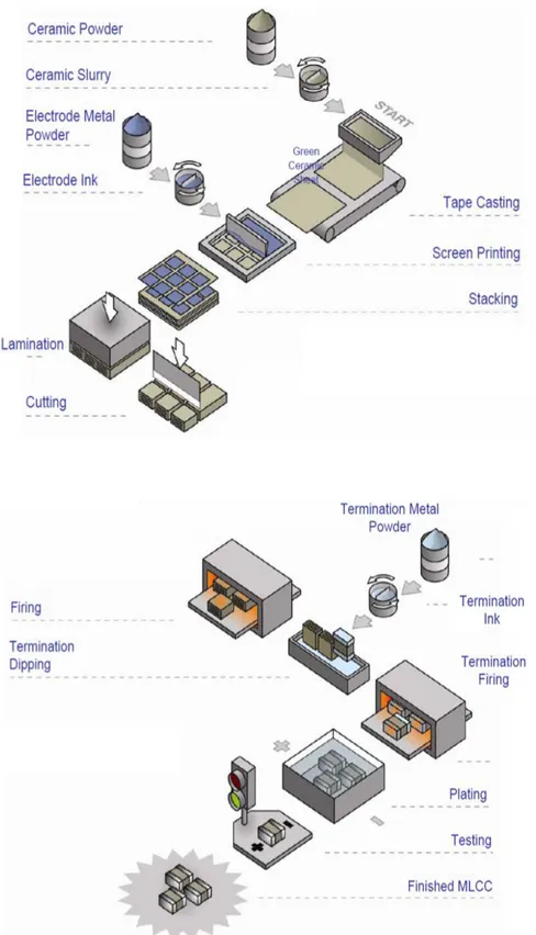
Figure 1.4. Basic structure of a multilayer ceramic capacitor. ... 36 Figure 1.5. MLCCs production process. Adapted from Basics of Ceramic Chip Capacitors by Johanson Dielectrics. 2008. ... 38
Figure 2.1. X7R MLCC ... 49 Figure 2.2. (A) Experimental set-up: (1) probe station Signatone S-1160; (2) heating chuck, Signatone model S-1060R; (3) sourcemeter unit Keithley 2410. (B) Enlarged view of the MLCC under test. ... 51
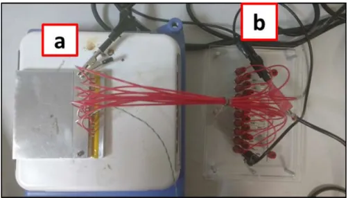
Figure 2.3. System for perform HALT over multiple samples at once. (A) HV power supplier (1 kV – 10 mA). (B) Plate with protective resistors in parallel to connect the samples that are inside (C) a metallic cell placed over a heating plate which temperature is monitored with (D) a multimeter reading the measurements of a thermocouple (K type). ... 52
Figure 2.4. (a) Plate with the protective resistors (1) connected in series with each sample; (b) View of an MLCC (1) inside the glass capillary (2) together with a spring (3); (c) View of the assembled connections (cables + springs) together with the MLCCs in the metallic plate interior canals; (d) Enlarged view of the interior of the cell, where red arrows highlight the samples inside of a glass capillary. ... 54
Figure 2.5. Upper view of the set-up. a. Metallic cell closed (with the samples inside) above the heating plate. b. Plate with protective resistors. ... 54 Figure 2.6. Representation of the data acquired in a HALT experiment. (A) Insulation resistance measurements at 600 V and 130 °C. (B) Insulation resistance measurements at 400 V and 170 °C. ... 56
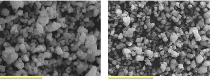
Figure 2.8. XRD patterns of BaTiO3 starting powders. JCPDS: 89-1428. ... 60 Figure 2.9. SEM images of (a) BT-A and (b) BT-B powders. Particles size: BT-A: 0.48 – 1.25 µm; BT-B: 0.46 – 0.81 µm. Scale bar: 5 µm. ... 61
Figure 2.10. Manual hydraulic press and pressing die during the making of green ceramics. ... 62 Figure 2.11. Sintering program A: Two-steps sintering program in air. (BT-A and BT-B ceramics undoped and with 2.5 and 5 wt% of Y2O3). ... 64 Figure 2.12. Representation of the sintering program at industrial level. ... 65 Figure 2.13. Thermal program for powders treated in air. ... 65
Figure 3.1. Current evolution of Groups A and B during HALT experiment at standard conditions (400 V, 140 °C). ... 72
Figure 3.2. Resistance evolution of individual MLCCs from (a) Group A, (b) Group B, and (c) Group C during HALT performed with 400 V and different temperatures. ... 74
Figure 3.3. Comparison of the TTF and current evolution for MLCCs from Groups A and B when tested under HALT standard conditions (400 V, 140 °C). ... 76
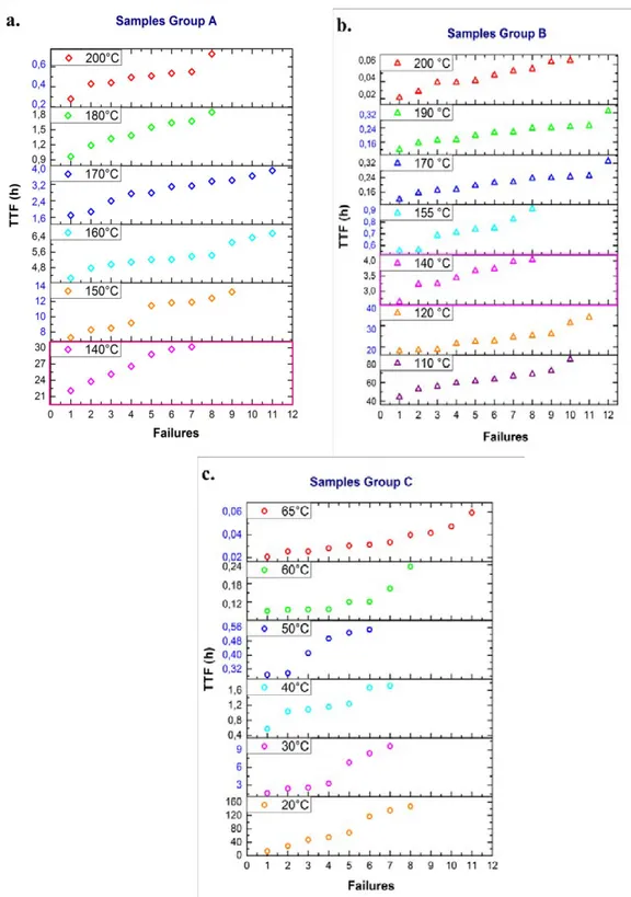
Figure 3.4. Correlation of the time-to-failure for the failures of each group of MLCCs. HALT conditions: 400 V and temperature indicated on the plots. (a) Group A, (b) Group B and (c) Group C. ... 77
Figure 3.5. Comparison of the TTF for MLCCs from (a) Group A, (b) Group B, and (c) Group C. HALT conditions: 400 V, temperature indicated on the plots. ... 78
Figure 3.6. Correlation of the time-to-failure for the failures of each group of MLCCs. HALT conditions: 600 V and temperature indicated on the plots. (a) Group A, (b) Group B and (c) Group C. ... 79
Figure 3.7. Comparison of the TTF for MLCCs from (a) Group A, (b) Group B, and (c) Group C. HALT conditions: 600 V, temperature indicated on the plots. ... 80
Figure 3.8. Weibull plot for Group A. HALT conditions: (a) 400 V, 140 – 230 °C and (b) 600 V, 140 – 220 °C. ... 86
Figure 3.9. Changes in the scale parameter of Group A as a function of the HALT temperature. The temperatures delimited by the dashed lines were considered for the Arrhenius plot in the next section. ... 88
Figure 3.10. Weibull plot for Group B. HALT conditions: (a) 400 V, 110 – 225 °C and (b) 600 V, 90 – 220 °C. ... 89
Figure 3.11. Changes in the scale parameter of Group B as a function of the HALT temperature. The temperatures delimited by the dashed lines were considered for the Arrhenius plot in the next section. ... 90
Figure 3.12. Weibull plot for Group C. HALT conditions: (a) 400 V, 20 – 90 °C and (b) 600 V, 20 – 80 °C. 92 Figure 3.13. Changes in the scale parameter of Group C as a function of the HALT temperature. The
temperatures delimited by the dashed lines were considered for the Arrhenius plot in the next section. ... 93
Figure 3.14. Characteristic life according the Arrhenius model for MLCCs from (a) Group A, (b) Group B, and (c) Group C according the electrical and thermal stress. Solid lines represent the best fits given by equation (3). ... 99
Figure 4.1. SEM images of BaTiO3 undoped raw powders and the respectively 5 wt% Y2O3-doped and thermally treated powders. (a) BT-A_0, (b) BT-A_5TT, (c) BT-B_1 (d) BT-B_5TT powders. Scale bar: 1µm ... 112
Figure 4.2. Variation of 2θ according the c/a ratio value, based on the cubic lattice 3.996 Å, for the planes (002). ... 113
Figure 4.3. X-ray diffraction patterns of raw BaTiO3 powders. JCPDS: 89-1428. ... 114
Figure 4.4. X-ray diffraction patterns of thermally treated (1350 °C) undoped BaTiO3 and Y2O3-doped BaTiO3 (2.5, 5.0 and 20.0 wt%) powders. Powders issued from (a) BT-A and (b) BT-B. ... 116
Figure 4.5. Enlargement in the zone around 45° for X-ray diffraction patterns of thermally treated (1350 °C) undoped BaTiO3 and Y2O3-doped BaTiO3 (2.5, 5.0 and 20.0 wt%) powders. ... 117
Figure 4.6. Density of the ceramics sintered in air as a function of Y2O3 concentration. ... 119
Figure 4.7. SEM images from (a) BT-A_2.5 and (b) BT-A_5 ceramics sintered in air. Scale bar: 1µm. ... 120
Figure 4.8. Size distribution of (a) BT-A_2.5 and (b) BT-A_5 ceramics sintered in air. ... 120
Figure 4.9. SEM images from (a) BT-B_1 and (b) BT-B_5 ceramics sintered in air. Scale bar: 1µm. ... 121
Figure 4.10. Mean size distribution of (a) BT-B_1 and (b) BT-B_5 ceramics sintered in air. ... 121
Figure 4.11. X-ray diffraction patterns of undoped BaTiO3 and 2.5 and 5.0 wt% Y2O3-doped BaTiO3 ceramics. Ceramics formed from (a) BT-A and (b) BT-B, sintered in air. ... 122
Figure 4.12. Density of BT-A ceramics sintered in a reducing atmosphere as a function of Y2O3 content. ... 125
Figure 4.13. Comparison of the BT-A ceramics density sintered using air or reducing atmosphere as a function of Y2O3 content. ... 125
Figure 4.14. SEM images from A ceramics sintered in reducing atmosphere. (a) A_5_sint, (b) BT-A_5_reox, and (c) BT-A_20_sint. Scale bar: 1µm. ... 126
Figure 4.16. XRD patterns of BT-A powder and ceramics sintered in reducing atmosphere and re-oxidized. Lateral enlargements of zone around 45° are presented for doped samples. ... 131
Figure 4.17. Density of BT-B ceramics sintered in a reducing atmosphere as a function of Y2O3 content. ... 133 Figure 4.18. Comparison of the BT-B ceramics density sintered using air or reducing atmosphere as a function of Y2O3 content. ... 134 Figure 4.19. SEM images from B ceramics sintered in reducing atmosphere. (a) B_1.5_sint, (b) BT-B_2_sint, and (c) BT-B_5_sint. Scale bar: 1 µm. ... 135
Figure 4.20. Mean size distribution of BT-B ceramics sintered in reducing atmosphere. (a) BT-B_1.5_sint., (b) BT-B_2_sint., and (c) BT-B_5_sint. ... 135
Figure 4.21. XRD patterns of BT-B powder and ceramics sintered in reducing atmosphere and re-oxidized. Lateral enlargements of zone around 45° are presented. ... 139
Figure 4.22. Density of BT-C ceramics sintered in a reducing atmosphere as a function of Y2O3 content. .. 141 Figure 4.23. SEM images from C ceramics sintered in reducing atmosphere. (a) C_1.5_sint, (b) BT-B_2_sint. Scale bar: 1 µm. ... 142
Figure 4.24. Size distribution of BT-C ceramics sintered in reducing atmosphere. (a) BT-C_1.5_sint., and (b) BT-C_2_sint. ... 143
Figure 4.25. XRD patterns of BT-C powder and ceramics sintered in reducing atmosphere and re-oxidized. Lateral enlargements of zone around 45° are presented. ... 144
Figure 4.26. Density values of ceramics sintered in reducing atmosphere at 1310 °C as a function of Y2O3 in the starting powder. ... 146
Table Index
Table 1.1. Effective ionic radii of various elements (Park et al, 2009; Tsur et al, 2001a). ... 28
Table 1.2. Types of MLCCs and specifications (Kahn, 1981; Kishi Mizuno, & Chazono, 2003). ... 36
Table 2.1. HALT parameters for the three groups of MLCCs. ... 52
Table 2.2. Chemical composition of BaTiO3 powders. ... 60
Table 2.3. Sample identification of prepared powders doped with Y2O3. ... 62
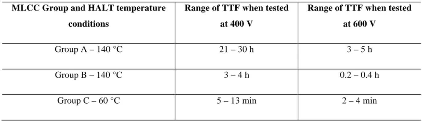
Table 3.1. TTF when HALT is performed using different voltages and the same temperature. ... 81
Table 3.2. Weibull parameters for MLCCs - Group A. ... 87
Table 3.3. Weibull parameters for MLCCs - Group B. ... 90
Table 3.4. Weibull parameters for MLCCs - Group C. ... 93
Table 3.5. Activation energy values obtained from Arrhenius-Weibull model for MLCCs tested under two different voltages and a range of temperatures. ... 100
Table 3.6. Voltage stress constant (n). ... 101
Table 4.1. Ba/Ti ratio and chemical composition of BaTiO3 powders. ... 110
Table 4.2. Additives and dopants on BaTiO3 dielectric formulation. ... 110
Table 4.3. Sample identification of prepared powders doped with Y2O3. ... 111
Table 4.4. Density of the ceramics sintered in air, two temperature steps: 1310 °C then 1150 °C for 15 h. . 118 Table 4.5. Secondary phases detected in the different powders and ceramics thermally treated and sintered in air, two temperature steps: 1310 °C then 1150 °C 15 h. ... 123
Table 4.7. Secondary phases detected in BT-A ceramics sintered in reducing atmosphere at 1310 °C. ... 132
Table 4.8. Density of BT-B ceramics sintered in reducing atmosphere at 1310 °C. ... 133
Table 4.9. Secondary phases detected in BT-B ceramics sintered in reducing atmosphere at 1310 °C. ... 140
Table 4.10. Chemical composition of BaTiO3 formulated powders. ... 140
Table 4.11. Density of BT-C ceramics sintered in reducing atmosphere at 1310 °C. ... 141
Table 4.12. Summary of secondary phases detected in ceramics sintered in reducing atmosphere and 1310 °C. ... 148
General Introduction
Nowadays, the electronic devices are part of our lives: computers, telephones, electrical appliances are some examples. Currently the presence of electronic components is increasing more and more in industries such as the automobile and aeronautics, as well as in in the devices or processes that require automation. One of the principal components of these devices is the capacitor, which main function is the energy storage. There are multiple types of capacitors, one of the most used are the multilayer ceramic capacitors (MLCCs). The MLCCs offer essential advantages due to their low cost, one of the reasons of its predominance in the electronics market. According to the application there are different kinds of MLCCs to choose, regarding principally the capacitance they offer but also the dielectric material and its performance under different conditions, such as the temperature. The characteristics of the MLCCs are going to be determined by extrinsic and intrinsic parameters; i.e., the nature, characteristics, synthesis and treatment of the dielectric material and the production process of the capacitors. These factors can influence on the final reliability of the capacitors and hence of the devices. For this reason, it is highly important to develop ceramic materials suitable for the different markets. One of the principal strategies to obtain reliable capacitors is to focus in the tailoring of the dielectric ceramic by modifying the material composition.
Barium titanate (BaTiO3) has been the most used material as the base for the dielectric of the
MLCCs due to properties such as its large permittivity. To enhance its electrical properties, it needs to be modified through the inclusion of several additives and dopants in the base formulation for the dielectric. The perovskite structure of the BaTiO3 has the ability to host these dopants, which
that it will also determine the reliability (lifetime) of the final product. The formulation of barium titanate powders includes as dopants rare-earth elements (REE). Among them, the Y2O3 is the most
common for the fabrication of multilayer ceramic capacitors with base-metal electrodes (BME-MLCCs) because it has a lower cost than Ho2O3, Er2O3 and Dy2O3 and provides similar properties.
Also, cations such as Mn2+, Mg2+ and Ca2+, that can contribute to the global distribution of the electronic defects generated when the doping ions are introduced into the lattice and during the capacitors fabrication process. In addition to these dopants, additives are added aiming to modify the production conditions, like the SiO2 used to lower sintering temperatures. The final properties
will result from the interactions that barium titanate, dopants and additives can have among each other under the specific sintering conditions. The complexity of the system is increased when given some conditions, secondary phases are formed. In previous works, these secondary phases, particularly those related to Y2O3 doping, are believed to be responsible for the long-term failure
mechanisms of MLCC’s under nominal operation.
This thesis work has the objective to analyze the role of Y2O3 as BaTiO3 dopant and its possible
contribution to the formation of secondary phases. The achievement of this objective involves two experimental blocks. First, the electrical characterization of MLCCs with Y2O3-doped BaTiO3 as
dielectric by the performance of high accelerated life tests (HALT) that lead to obtain life indicators. Secondly, the development of a doping study that includes the preparation of powders and ceramics under different sintering conditions using Y2O3 as dopant and two kinds of BaTiO3
powders (one pure and two formulated for industrial applications).
This thesis manuscript is divided in four chapters.
The first chapter is a bibliographic introduction in order to situate this work in the current context. It presents the general properties of the BaTiO3, and how they can be enhanced by the use of dopants
The Chapter 2 describes the different experimental methods as well as the characterization techniques used in this work.
In the Chapter 3 is presented the electrical characterization of multilayer ceramic capacitors (MLCCs) using accelerated life tests (HALT) to determine the mean time to failure (MTTF) of each group of samples and perform Weibull statistical analyses that can be used in conjunction with the Arrhenius model to obtain the activation energy (Ea) value related to the failure of the capacitors
under determined conditions.
In the Chapter 4 is presented the Y2O3-doping of two types of BaTiO3 powders (one reagent grade
and the other two commercially formulated) and the preparation of ceramics issued from those powders under different sintering conditions. The influence of the dopant and the presence of secondary phases over the structural and microstructural BaTiO3 properties are described in this
chapter.
Chapter 1
Introduction
Barium titanate (BaTiO3) has attracted the attention for decades both, in the fundamental research
field as in industry for device applications. This is a noteworthy ferroelectric material because it has a high ferroelectric activity, dielectric constant and spontaneous polarization (Li, Xu, Chu, Fu, & Hao, 2009) and presents a high resistivity (1010–1012 Ω cm) (Belous, V’yunov, Glinchuk, Laguta, & Makovez, 2008). For the above mentioned, barium titanate has a great potential for technological applications in the electronics industry. In fact, due to its high dielectric constant, low dielectric loss and superior performance at high frequency, one of its most common applications is as the dielectric material for ceramic capacitors (Wang, Chen, Gui, & Li, 2016). Among these BT-based ceramic capacitors, the multilayer ceramic capacitors (MLCCs) are widely used in military, automotive and telecommunication applications in which the devices are subjected to meaningful changes in temperature, voltages and frequencies (Wang et al, 2001). Nonetheless, when the BaTiO3 is pure exhibits a great change in dielectric constant near the Curie temperature (Tc) which
renders the ceramic material unsuitable for capacitor applications. For this reason, the capacitor BT-based formulations must be chemically modified to meet the required capacitance-temperature characteristics (X. H. Wang et al, 2001; J. Wang et al, 2016; T. Wang, 2009).
own their distinctive qualities due to the composition of the raw materials as well as the way they are processed. They are divided in two types of materials: traditional and technical ceramics. The first group (alumino-silicate) is generally produced from natural raw materials (clay, feldspar, kaolin, quartz) and they are generally implemented by casting (slip). The latter (metal-metalloid associations) are obtained by sintering or by electrofusion (the oxides are poured directly into a mold) (Fantozzi, Niepce, & Bonnefont, 2013). Actually, the second group has inspired the definition of the term “ceramics”, as expressed by M. Barsoum & M. W. Barsoum (2002): “solid compounds that are formed by the application of heat, and sometimes heat plus pressure, comprising at least two elements provided one of them is a non-metal or a nonmetallic element solid. The other element(s) may be a metal(s) or another nonmetallic elemental solid(s)”.
This thesis work is focused on BaTiO3 ceramics. These ceramics belong to the technical ceramics
classification of the electronics that are semiconductors (thermistors, resistors).
1.2. BaTiO
3– Structural characteristics
Barium titanate (BaTiO3) is a ceramic material that has been widely studied due to its excellent
dielectric, ferroelectric and piezoelectric properties (Nikulin, 1988; He et al., 2013). It presents a stoichiometric cubic perovskite of ABO3-type (A = alkaline-earth element and B = transition metal)
containing sties with cubic environments of oxygen while B-sites are in an octahedral environment with corner-linked octahedral, as shown in Fig. 1.1. Below the Curie temperature (Tc) the BaTiO3 is
non-centrosymmetric, and can present a crystal distortion (Valdez-Nava et al, 2010).
Barium titanate has five crystalline forms: hexagonal, cubic, tetragonal, orthorhombic and rhombohedral, occurring at various phase transition temperatures: 1432 °C, 130 °C, 5 °C and -90 °C, respectively. The most stable phase at room temperature is the tetragonal phase; this is the most used form because of its excellent ferroelectric, piezoelectric and thermoelectric properties (Li et al,
Figure 1.1. Scheme of the BaTiO3 perovskite structure. A) Cubic lattice (above Curie temperature, 120°C). B) Tetragonal lattice (below Curie temperature, 120°C). (Richerson,2005).
1.3. Role of the dopants on the electrical properties of BaTiO
3The crystal structure of this oxide belongs to the perovskite type, as shown in Fig. 1.1. This structure allows it to present a high dielectric constant. Pure BT exhibits a great change in dielectric constant near Curie temperature (Tc) 120°C (X. H. Wang et al, 2001). As a ferroelectric material, BT has a temperature point known as the Curie temperature (Tc), above which it becomes substantially non-electric, i.e. dielectric (Nikulin, 1988). If the material is above Tc (and up to 1400°C) it is centrosymmetric and paraelectric. Although barium titanate presents great electrical properties, it cannot be used in its pure form as a dielectric material.
Many efforts have been done in order to enhance barium titanate electrical properties for its different applications. One of the most common and effective methods has been to design the formulation including several additives and dopants. The difference between additives and dopants is not defined with exactitude for this field of study. However, it is usually considered that the additives contribute to the improvement of the production process while the dopants are supposed to have a direct impact over the final properties of the material, i.e. the dielectric properties. In this
Cations such as Mn2+, Ca2+ and Mg2+ are added as dopants that can partially compensate the electrons and holes that the system might have due to the presence of oxygen vacancies (Yoon et al., 2007; Yoon, Kang, Kwon, & Hur, 2010).
Manganese can perform a double role; it can compensate the oxygen vacancies as an acceptor being incorporated at the Ti4+ sites, but it can act as well as an additive inhibiting an excessive grain growth. It can take different valences (Mn2+, Mn3+ or even Mn4+) during the post-sintering process, being considered as an unstable acceptor-type dopant (Paunovic, Mitic, Marjanovic, & Kocic, 2016) but helps the material to keep a high insulation resistance while accepting electrons to form a lower oxidation state (Lee, Tseng, & Hennings, 2001).
Calcium is added to contribute as well to limit the oxygen vacancies concentration which improves the reliability, and can dissolve in the BT lattice participating in the core-shell formation (Yoon et al., 2010). The mechanism by which calcium exerts these effects has been argued along decades, which is related to things like the final application of the Ca-doped BT materials and the different ways that Ca2+ can be added. However, it has been reported that the occupation site of Ca2+ is critical for it can exert the effect of increase the resistance degradation (Fang, & Shuei, 1999; Han, Appleby, & Smyth, 1987; Völtzke, Abicht, Pippel, & Woltersdorf, 2000; Zhu, Zhang, & Chen, 2013).
The introduction of dopants that can be donors or acceptors also modifies the structure of barium titanate and can contribute to the creation of chemical inhomogeneity like core-shell structure (T. Wang, X.H. Wang, Wen, & Li, 2009; Kim et al, 2008; Armstrong, & Buchanan, 1990). Magnesium has been reported as a key cation in the formation of the core-shell structure and the inhibition of grain grown since it remains at the grain boundaries while the RE ions dissolve in the BT lattice (Huang et al., 2015; Kim et al., 2008).
The core-shell structure consists of pure ferroelectric BT (tetragonal structure) in a core that is surrounded by a shell of BT containing dopants and additives (mixture of tetragonal and cubic phases) with paraelectric behavior, as shown in the Fig. 1.2. (Kim et al, 2008). Hennings and Rosenstein (1984) reported the formation mechanism of this structure. They were able to show that the cores are the same phases as the shells, since the paraelectric shells grew epitaxially on the ferroelectric cores. Considering the core-shell structures are not thermodynamically stable, its formation will be affected both by the sintering temperature and the donor-acceptor ratio (T. Wang et al, 2009).
Figure 1.2. Transmission electron micrographs of core-shell structures in doped BT ceramics. (A) TEM bright field image of a X7R-type BaTiO3 ceramics by Grogger, Hofer, Warbichler, Feltz, & Ottlinger, (1998).
(B) TEM of a typical core-shell grain in a BT specimen doped with yttrium and magnesium by Kim et al.
(2008).
The microstructure of the ceramics resulting from the elaboration process will have an influence on the dielectric properties. For instance, the milling process can cause defects on the particles’ surface and activate the diffusion of the additives into the grains. It has been reported that as the milling time increases, the shell region gets thicker and the core region gets smaller, leading to a high chemical homogeneity at the core-shell interface increases (Wang et al., 2009).
dopants. SiO2 has the ability to form a liquid phase from the ternary system BaO-TiO2-SiO2,
diminishing the eutectic point from 1320°C to near 1260°C (Felgner, Müller, Langhammer, & Abicht, 2001; Liu & Roseman, 1999; Ösküz, Torman, S. Sen, & U. Sen, 2016). This ternary eutectic point is well known and corresponds to the BaTiO3 – Ba6Ti17O40 system at approximately
1330 °C (Felgner et al., 2001). When SiO2 is present, this temperature decreases to about 1280 °C -
1260 °C. This is the reason why SiO2 is considered as a suitable additive to produce ceramics with
high density while lowering the sintering temperature, and it may even induce an improvement in the dielectric properties of BT (Öskus et al., 2016; Wu et al., 2007). Cheng (1989) also reported that the presence of SiO2 and TiO2, leaded to the formation of a liquid-phase former that enhanced the
ionic diffusion, resulting in a uniform microstructure. This liquid phase also purified the grain interior, increasing the grain conductivity. He also evidenced that the SiO2 and TiO2 are located at
the grain boundaries influencing only the microstructure, not the electrical properties. The liquid phase has been evidenced in studies such as the one conducted by Wu et al. (2007) through TEM analyses as shown in Fig. 1.3.
Figure 1.3. (a) Glassy second phase at triple-grain junction with selected area diffraction patterns of BaTiO3 grain inset (BF image), (b) high-resolution image of BaTiO3-glass interface showing an amorphous nature, and (c) energy-dispersive X-ray spectroscopy spectra for triple junction and BaTiO3 grain (Bo) (TEM) (Wu et
Despite the advantages of using sintering additives, the interactions that can take place between them and the BT matrix, can turn the structural and electrical nature modifications of the doped material into undesired ways. Chemical defects and even secondary phases, such as Ba2TiSi2O8 and
Ca2Y8Si6O26 have been reported in formulated BT-based X7R MLCCs (Wu et al., 2007). Those
phases could lead to the deterioration of the electrical properties that are supposed to be enhanced by the additives and dopants presence (Liu & Roseman, 1999; Öskus et al., 2016). Yan et al. (2016) reported that when adding 0.5 wt% of SiO2 to BaTiO3, no second phase was detected and it showed
homogeneous microstructure with small grains. However, with further increase of SiO2 addition to
1 and 2 wt%, Ba2TiSi2O8 secondary phase was detected and the dielectric constant of those
ceramics at the Tc decreased gradually.
Finally, rare-earth oxides are added as well as dopants and they can interact, due to their donor or acceptor ionic behavior, creating chemical defects and activating compensation mechanisms. The doping of BT with rare-earth ions (e.g. Y3+, Dy3+, Ho3+) improves its dielectric performance. For this reason, the researches in materials science and electronics engineering to improve the dielectric properties of the BaTiO3 as a dielectric base material and modify it directing the objectives towards
the market necessities, has highly increased the last decades. Gong, Wang, Zhang, & Li (2016) reported an increase of the reliability of co-doped BaTiO3-based MLCCs when using Ho
3+
and Dy3+. These dopants present a synergistic effect exhibiting a better insulation degradation behavior compared with the doped samples containing just one of the two. Similar results have been reported for donor- and acceptor-cosubstituted BT, which have shown a better insulation resistance and life stability. The most common of these systems is BaTiO3-MgO-R2O3, with R = La
3+
, Gd3+, Dy3+, Ho3+, Er3+, Y3+, Yb3+ (Kuo, Wang & Tsai, 2006). The doping behaviors of R = Ho3+, Dy3+ and Y3+ have been reported by authors like Makovek, Samardžija, & Drofenik, (2004). They observed that these ions have similar solubility in BaTiO3 lattice and their incorporation into it is mainly
the measure in which the RE ions are going to be incorporated in each site. Park et al, (2009) compared the doping behaviors of these RE ions in BaTiO3-MgO-R2O3 systems, obtaining the
densest ceramics with the Dy3+ ions, which exhibited the better shell formation as well due to a higher solubility compared to the Y3+ and Ho3+ ions. However, Y- and Ho-doped ceramics showed a most stable microstructure at high temperature. The similarities in the doping behavior of these particular three ions can be due to its similar ionic radius. Some of the BT dopants with their respective ionic radii according the coordination site they can occupy are shown in the Table 1.1. The ionic radius determines the occupation site in the BT lattice of the RE dopants. Larger RE ions such as La3+ and Sm3+ are predominantly donor dopants, occupying the A-site. Smaller ions like the Yb3+ are acceptor dopants; they occupy the B-site. The ions with intermediate ionic size (Dy3+, Ho3+, Er3+, Y3+) can be placed both in A- and B-sites, presenting both donor and acceptor dopant behavior (Kuo et al, 2006; Park et al, 2009; Tsur, Hitomi, Scrymgeour, & Randall, 2001a).
Table 1.1. Effective ionic radii of various elements (Park et al, 2009; Tsur et al, 2001a).
Ion
Ionic radius (Å)
B-site (6 coordination) A-site (12 coordination)
Ba2+ 1.610 Ti4+ 0.605 Mg2+ 0.720 Dy3+ 0.912 1.255 Ho3+ 0.901 1.234 Y3+ 0.900 1.234
presence of dopants can lead to a transformation from a well-defined tetragonal phase to a mixture of tetragonal phases or even a new structural phase. In the literature this change of phase is usually described as a mixture of tetragonal and cubic phases and denominated as a “pseudo-cubic” phase. As previously mentioned, the additives and sintering conditions affect the microstructure as well. For instance, the diffusion of oxygen atoms through the grain boundaries into the grains, to annihilate oxygen vacancies, can be faster during the cooling step. As a result, barium vacancies remain at the grain boundaries and form high-resistance regions. This increases the ceramics resistivity (Cheng, 1989). Besides the dielectric properties, the ferroelectric characteristics can also be modified. Shifts in transition temperatures or the broadening of the ε-T curve (diffuseness of the ferroelectric transition) can be some of the effects of dopants. Depending on the nature of the incorporated dopant in the BT lattice, it can go from classical ferroelectric to diffuse ferroelectric or even relaxor (Petrović, Bobić, Ramoška, Banys, & Stojanović, 2011). Also, the electrical behavior can be altered by the dopant concentration, which can lead to a dielectric or semi-conductivity behavior (Urek, Drofenik, & Makovec, 2000).
Two of the most principal applications for barium titanate are the positive temperature coefficient resistors (PTCRs) and the multilayer ceramic capacitors (MLCCs). The formulation for both of them is tailored with the incorporation RE cations to control conductivity and electrical degradation, respectively (Tsur, Dunbar & Randall, 2001b). The trivalent RE cations are of particular interest thanks to its amphoteric behavior. These substitutions cause a charge imbalance in the system that can be compensated either ionically under oxidizing conditions or electronically under reducing conditions (Fu, Mi, Wessel, & Tietz 2008; Makovek et al., 2004). Compensation mechanisms have been proposed (J. Zhi, Chen, Y. Zhi, Vilarinho, & Baptista, 1999; Jeong, Lee, & Han, 2005; Paredes-Olguín, Lira-Hernández, Gómez-Yañez, & Espino-Cortés, 2013) as illustrated below using the Kröger-Vink notation, when the dopant is Y2O3:
• When Ba2+ is substituted: !!!! !" !"#$!! → 2!!". + 2!′ (1) 3!!!! !" !"#$!! → 6!!"∙ + !!"!!!!+ !!"!! (2) • When Ti4+ is substituted: !!!! !" !"#$!! → 2!!"! + 2ℎ∙ (3) !!!! !" !"#$!! → 2!!"! + ! !∙∙ (4)
All mechanisms (1) to (4) might be active at the same time. However, the sintering parameters (temperature and !!!) will lead to the predominance of one of them. The dominant mechanism will determine the electrical properties of the doped sample, such as its resistivity. A decrease in the resistivity can be due to the presence of charge carriers, as in mechanisms (1) and (3). If (1) is the prevailing mechanism, ceramic will behave as an n-type semiconductor. Mechanism (3) will lead to a p-type behavior. On the other hand, if mechanism (4) is leading, the ceramic can be an oxygen conductor. On the basis of thermodynamic analyses, the mechanisms (3) and (4) are more probable to occur (Zhi et al., 1999; Paredes-Olguín et al., 2013). However, in Y-doping cases, it has been observed that if the concentration is less than 1 %, mechanism (1) is prevalent (Paredes-Olguín et al., 2013). The behavior as donor or acceptor of these RE cations will be also affected by the A/B ratio. An excess of BaO or TiO2 will influence the probability of A- or B-site occupation. In the
presence of an BaO excess, Y3+ acts as an acceptor, while it behaves like a donor if there is an TiO2
excess (Makovek et al., 2004). Y2O3 is a common BT-dopant and the most suitable rare-earth oxide
Known as the “magic ions”, Dy3+, Ho3+ and Y3+, are categorized as helpful for the lifetime of the MLCCs (Tsur et al., 2001a,b) for this reason, the amphoteric RE cations have been the most used for this type of applications. Since the optimization of industrial processes is crucial it is a determining factor as well at the moment to set the sintering parameters. Indeed, low sintering temperatures are preferred by industries for economic reasons.
In this work the Y2O3 was chosen as dopant because of its wide use in the dielectric formulations
for ceramic capacitors. The thermodynamic and kinetic factors that might influence its occupation site as well as the electrical properties of the ceramics will be discussed below.
1.4. Role of Y
2O
3The formulation of BaTiO3 (BT) materials, used in the manufacturing of the MLCCs, must be
tailored to control the electrical properties, especially at high temperature and under high electric field (Ashburn & Skamser, 2008; Yoon, Park, Hong & Sinn, 2007). For this purpose, several additives and dopants are added to BaTiO3. One of the most used dopants is the Y2O3, which is
added with the aim to generate compensation mechanisms that contribute to improving the reliability of the capacitors.
The Y3+ has an ionic radius of 0.107 nm, it is intermediate between that of the Ba2+ ion (0.161 nm) and the Ti4+ ion (0.06 nm). Therefore Y3+ can occupy either Ba2+ or Ti4+ cation site in the BT lattice (Wang et al., 2014; Tsur et al., 2001a). This allows Y3+ to behave as acceptor or donor according to the position in the lattice. The inclusion of the Y3+ ion in the BT structure depends on kinetic and thermodynamic factors (Makovec et al., 2004). It is reported that the formation energy of !!"∙ + !!"!! is 7.23 eV whereas it is only 4.35 eV to form a !!"∙ + !!"!!!! defect (Belous, V’yunov,
the dopant concentration and its solubility. Yttrium cations have different solubility in Ba- and in Ti-sites. Zhi et al. (1999) indicated a solubility of Y3+ at the Ba-site of about 1.5 at% when sintered in air at 1440 – 1470°C, while it reaches 4 at% when sintered under reducing conditions (V’yunov, Kovalenko, Belous, & Belyakov, 2005). For the Ti-sites instead, the solubility is higher, approximately 12.2 at% at 1515°C when sintering in air. Wang et al. (2014) reported that the introduction of Y3+ in the BT lattice, can lead to structural changes, as the phase transformation from tetragonal to cubic.
The amount of yttrium ions can be spent in different processes occurring in the system during the processing of the ceramic materials. Belous et al. (2008) studied yttrium-doped BT, identifying in which processes is expended the dopant. It is known that the raw materials may contain impurities. In this case paramagnetic impurities were identified as able to occupy Ti-sites. Thus, some part of the Y3+ can participate in an exchange of them. Yttrium also influences the charge compensation mechanisms. And as a collateral effect, it has been found it can participate in the formation of precipitates such as Ba6Ti17O40 and Y2Ti2O7. These secondary phases have been usually found when
the solid solubility of the dopant in the BT is surpassed.
With the appropriate amount of dopants, the structural, optical and electrical properties of a BT-doped system can be improved (Hernández Lara et al., 2017). On the other hand, there are numerous reports where the formation of secondary phases has been observed when doping BT with rare-earth elements (REE) (Belous et al., 2008; Yoon et al., 2007; Zhang et al., 2016). The formation of these precipitates depends on different factors, i.e. the sintering conditions and the dopant concentration (M. T. Buscaglia, Viviani, M. Buscaglia, Bottino, & Nanni, 2002). These secondary phases are usually formed when the amount of dopant is above of its solubility limit in the BT-lattice. This excess of dopant can lead to its interaction with other free ions present in the system, like Ti4+. Then, if the conditions are appropriate, a precipitate will be formed. Some of the
2007), Ba6Ti17O40 (Belous et al., 2008), Y2TiO5 (Yoon et al., 2007), and one of the most common
when doping with RE oxides (Dy2O3, Er2O3, Y2O3 and Ho2O3), is the pyrochlore-type phase,
R2Ti2O7 (Jeong et al., 2005). Among the pyrochlores, Er2Ti2O7 (Buscaglia et al., 2002), Gd2Ti2O7
(Hernández Lara et al., 2017), Ho2Ti2O7 (Makovec et al., 2004) and Y2Ti2O7 (Yoon et al., 2007;
Zhang et al., 2016) have been reported. Y2Ti2O7 is suspected to be detrimental to the reliability of
BT-based MLCCs (Yoon et al., 2007; Zhang et al., 2016).
The effect of the presence of these secondary phases over the BaTiO3 structural and dielectric
properties is of high interest for industrial applications. Several authors have reported a detrimental effect of Y2Ti2O7 on BT dielectric performance (Wu et al., 2007; Yoon et al., 2007; Zhang et al.,
2016). The yttrium pyrochlore (Y2Ti2O7) has a highly conductive nature and is suspected to be
related with the resistance degradation of the material through the acceleration of oxygen vacancies electromigration (Zhang et al., 2016). The investigation of the formation parameters and possible effects of this phase is of high interest in the academic and industrial field since Y2O3 is a one of the
most frequent dopants used in the MLCCs production.
1.5. Sintering atmosphere influence over dopant occupancy in BT-doped
ceramics
One of the most important parameters to obtain a BT material with the appropriate properties for its application as ceramic dielectric is the oxygen partial pressure (!!!) during sintering treatment. !!! affects the incorporation of dopants into the BT-lattice (Buscaglia et al., 2002; Tsur et al., 2001b). The site occupancy of dopants in BT-lattice is restrained by the valence of the ion, its size, the A/B ratio (i.e. the activity of Ti in the system) and by the oxygen vacancies concentration. It has been observed that the !!! influences the charge compensation mechanisms (ionically or
formation of precipitates. Furthermore, the changes induced by the !!! significantly affects the electrical behavior (Fu et al., 2008).
Either a reducing or an oxidizing sintering atmosphere can be used for the production of BT-doped ceramics. However, taking into account the cost reduction at industry level due to the use of nickel for the inner electrodes instead of the expensive noble metals previously employed, (palladium or silver palladium alloys), one of the factors that forces the use of reducing atmospheres is to protect Ni-electrodes from oxidation. Thus, the process must to be carried out in reducing atmospheres, such as CO/CO2 or N2/H2, being the latter the most used (Albertsen, Hennings, & Steigelmann,
1998; Hagenbeck & Waser, 1998; Okino et al., 1994). Meanwhile, in the research field, either reducing or oxidizing atmospheres have been utilized.
The control of !!!employed during the sintering of BT-doped ceramics can even contribute to the formation of Ti3+ ions, assuming the substitution of Y3+ for Ba2+ in the BT-lattice. Tien & Carlson
(1963) performed some experiments to determine the relation between the degree of oxidation and the resistivity-temperature characteristics of Y-doped polycrystalline BT. They found that the oxygen partial pressure increases the slope of temperature-resistivity curves above Tc and the resistivity at room temperature. This behavior is related to the amount of Ti3+ present in the system. Under equilibrium conditions, the relation between !!! and Ti
3+
concentration is described by: 2Ti4+ + O2- ⇌ 2Ti3+ + ½ O2. Previous reaction is overlapped by the Y
3+
dopant, its level and the prevailing equilibrium conditions will then determine the concentration of Ti3+. Following the expression for the equilibrium constant ! = (!"!!)!!!!!/!
(!"!!)!(!!!) , [Ti
3+
] is constant at a given temperature and equilibrium conditions as determined by dopant amount and the prevailing !!!. If the !!! is constant as the temperature is decreasing, then the equilibrium constant will be decreasing which as well will dictate an increase of Ti3+ concentration, and this will influence the electrical behavior of
Tsur et al. (2001a, 2001b) investigated the site occupancy of rare earth ions in the BT-lattice according to the atmosphere conditions. They found that when BT is fired at low !!! and high temperatures, dopants such as Er, Y, Ho and Dy are amphoteric (Tsur et al., 2001a). They also observed that samples fired in air present larger cell volumes than the ones sintered in reduced atmospheres. The latter is due to the lower presence of oxygen vacancies in air sintered samples, thus site occupancy is directed towards more B-site occupancy (Tsur et al., 2001b).
1.6. Multilayer ceramic capacitors (MLCCs)
In the past decades, the electronic devices design has gone toward the miniaturization and reduction of power consumption. This trend requires high reliability for the electronic components (Shimada, Utsumi, Yonezawa, & Takamizawa, 1981). Among the most important electronic items are the Multilayer Ceramic Capacitors (MLCCs) (Fig. 1.4). MLCCs were developed in the 1960s and its use increased in the 1980s (Pan & Randall, 2010). These pieces are used in strongly growing markets (Acosta, Zang, Jo & Rödel, 2012), making up approximately 30% of the total components in a typical hybrid circuit module (Futureelectronics.com. (n.d.)). They present an economical volumetric efficiency for capacitance and high reliability. MLCCs are characterized by a high dielectric constant (K) and thinner dielectric layers (Jain, Fung, Hsiao, & Chan, 2010). MLCCs can be broadly divided, depending on the application, into two types: for temperature compensation and for high-dielectric constant. MLCCs for high-dielectric constant use barium titanate as the dielectric component. Among this type of capacitors, the X7R is the most stable, covering a broad spectrum of applications. X7R formulations are called “temperature stable” ceramics, which allows apply them widely in miniaturization of electronic components (Li, Zhang, Zhou, Chen, & Wang, 2007).
Figure 1.4. Basic structure of a multilayer ceramic capacitor.
Multilayer ceramic capacitors are classified in three classes according the Electronic Industry Alliance (EIA). Class I are Temperature Compensating capacitors, they are known as COG (a.k.a. NPO). Class II is known as Stable capacitors, the most common among them are X7R, X5R and Y5V. Finally, class III: Z5U, known as the General Purpose capacitors (Ashburn, & Skamser, 2008; Pan & Randall, 2010; Standard, E.I.A., 2002). The specifications of classes I and II are shown in
Table 1.2. They can be classified by its rated voltage, tolerance, type of dielectric, capacitance, packaging type and case size. The most common values for capacitance are 10 nF, 100 nF and 1 µF. The rated voltage (RV) can be between 4 V and 10 kV, and the most common capacitors have a RV of 16, 25, 50 or 100 V (Futureelectronics.com. (n.d.)). The EIA specification for X7R MLCCs is a temperature variation of capacitance (ΔC/C) within ± 15 % from -55 °C to 125 °C. (Li et al., 2007; Park et al., 2009).
Table 1.2. Types of MLCCs and specifications (Kahn, 1981; Kishi Mizuno, & Chazono, 2003).
EIA Designation Class Temperature range (°C) ΔC/C (%) K value up to BT content (%) Other dopants Grain size (µm)
C0G (NPO) I -55 to 125 ± 30 100 10-50 TiO2, CaTiO3, Nd2Ti2O7 1 X7R II -55 to 125 ± 15 4000 90-98 MgO, MnO, Nb2O5, CoO, Rare-earth elements <1.5
Multilayer ceramic capacitors of Classes II and III exhibit aging characteristics. The capacitance of Class II devices typically falls 10 % with applied voltages of 50 to 70 % of the device’s maximum working voltage. Class III devices lose capacitance starting at 10 % of the maximum working voltage and exhibit as little as 30% of their nameplate value at 90 % of their voltage range (Pan & Randall, 2010).
The capacitor technology has changed according to the industrial and commercial demands. Since many of MLCCs applications are manipulated at extreme operational conditions, like high temperatures (beyond 200 °C), the capacitors must be processed out under high degree requirements to ensure a high-yield, large-scale, low-cost production process (Kahn, 1981). MLCCs with X7R-formulation based on BaTiO3 dielectric material, are usually produced under a sintering process
with a temperature between 1200 °C and 1300 °C and low !!! of about 10
-9
– 10-11 atm. This is followed by a re-oxidation step at 800° - 1000°C in !!! between 10
-6
– 10-8 atm. (Wu et al., 2007). This last step contributes as well to the attempt to diminish the contribution of oxygen vacancies (Pan & Randall, 2010). A whole general view of the industrial production process of these capacitors is shown in the Fig. 1.5.
The characteristics of each MLCC type challenge a highest quality for its production. Each step during this process must be carefully supervised, taking care of some key factors that will critically influence the lifetime and resistance degradation of the capacitors. Some of the considerations to take into account, as it has been explained, are the characteristics of the starting BT powder and the features of the final formulation to be applied, i.e. optimization of additives and dopants. There are as well some aspects related particularly to the process, as the coating of the dielectric material and the control of atmospheric conditions during thermal processing. As long as the production steps are under control, the process will be robust ensuring a high-quality product (Ashburn & Skamser,
Figure 1.5. MLCCs production process. Adapted from Basics of Ceramic Chip Capacitors by Johanson Dielectrics. 2008.
Nevertheless, even though research in the last decades has allowed to the industries the optimization of the production process, exhibiting a great improvement in the technology of the electronic field, some failures are still observed in some cases.
Two failure modes have been identified in Base-Metal-Electrode (BME) Multilayer Ceramic Capacitors (MLCCs): catastrophic and slow degradation. Catastrophic failures are mainly due to present processing defects (extrinsic defects), such as voids, cracks and delaminations. These are characterized by a time-accelerating increase in leakage current. On the other hand, the slow degradation failures are related with the electromigration of oxygen vacancies, which are considered intrinsic defects, and are characterized by a near-linear increase in leakage current against stress time (Liu, 2015).
These failure modes can be distinguished using a 2-parameter Weibull plot. The early (catastrophic) failures can be distinguished by a slope parameter of β >1. This β value indicates that these are not infant mortalities (Liu & Sampson, 2012).
Early failures have been related to the decrease of the dielectric thickness, being triggered by external electrical overstress. This has represented a problem to control a high reliability with the miniaturization of MLCCs. The breakdown leakage current that characterize an early failure is an avalanche-like type (Liu & Sampson, 2012). Since, as mentioned before, these failures are related to extrinsic defects, i.e. minor construction defects introduced during fabrication of the capacitors, the production control and quality requirements are a crucial factor to obtain a reliable final product.
It has been reported that insulation resistance (IR) degradation of BT-based BME-MLCCs might be related with three probable aspects: the dielectric layer, the BT grain boundaries, and the internal electrode interfaces between Ni-BaTiO3 (Liu, 2015).
References
Acosta, M., Zang, J., Jo, W., & Rödel, J. (2012). High-temperature dielectrics in CaZrO3-modified
Bi1/2Na1/2TiO3-based lead-free ceramics. Journal of the European Ceramic Society, 32(16),
4327-4334.
Albertsen, K., Hennings, D., & Steigelmann, O. (1998). Donor-acceptor charge complex formation in barium titanate ceramics: Role of firing atmosphere. Journal of electroceramics, 2(3), 193-198.
Ashburn, T., & Skamser, D. (2008, January). Highly accelerated testing of capacitors for medical applications. In Proceedings of the 5th SMTA Medical Electronics Symposium. California, USA.
Armstrong, T. R., & Buchanan, R. C. (1990). Influence of Core-Shell Grains on the Internal Stress State and Permittivity Response of Zirconia-Modified Barium Titanate. Journal of the American
Ceramic Society, 73(5), 1268-1273.
Barsoum, M., & Barsoum, M. W. (2002). Fundamentals of ceramics. CRC press.
Belous, A., V’yunov, O., Kovalenko, L., & Makovec, D. (2005). Redox processes in highly yttrium-doped barium titanate. Journal of Solid State Chemistry, 178(5), 1367-1375.
Belous, A., V’yunov, O., Glinchuk, M., Laguta, V., & Makovez, D. (2008). Redox processes at grain boundaries in barium titanate-based polycrystalline ferroelectrics semiconductors. Journal of
materials science, 43(9), 3320-3326.
Buscaglia, M. T., Viviani, M., Buscaglia, V., Bottino, C., & Nanni, P. (2002). Incorporation of Er3+ into BaTiO3. Journal of the American Ceramic Society, 85(6), 1569-1575.
Cheng, H. F. (1989). Effect of sintering aids on the electrical properties of positive temperature coefficient of resistivity BaTiO3 ceramics. Journal of Applied Physics, 66(3), 1382-1387.
Fang, T. T., & Shuei, J. T. (1999). Experimental assessment of the inhibition of reduction of Ca2+ -doped barium titanate in a reducing atmosphere. Journal of materials research, 14(5), 1910-1915.
Fantozzi, G., Niepce, J. C., & Bonnefont, G. (2013). Les céramiques industrielles: Propriétés, mise
en forme et applications. Dunod.
Felgner, K. H., Müller, T., Langhammer, H. T., & Abicht, H. P. (2001). Investigations on the liquid phase in barium titanate ceramics with silica additives. Journal of the European Ceramic Society,
21(10), 1657-1660.
Fu, Q. X., Mi, S. B., Wessel, E., & Tietz, F. (2008). Influence of sintering conditions on microstructure and electrical conductivity of yttrium-substituted SrTiO3. Journal of the European Ceramic Society, 28(4), 811-820.
Grogger, W., Hofer, F., Warbichler, P., Feltz, A., & Ottlinger, M. (1998). Imaging of the core–shell structure of doped BaTiO3 ceramics by energy filtering TEM. Physica status solidi (a), 166(1),
315-325.
Gong, H., Wang, X., Zhang, S., & Li, L. (2016). Synergistic effect of rare-earth elements on the dielectric properties and reliability of BaTiO3-based ceramics for multilayer ceramic capacitors. Materials Research Bulletin, 73, 233-239.
Guha, J. P. and Kolar, D., Phase equilibria, sintering characteristics and dielectric properties in the BaTiO3-rich portion of the system BaO–TiO2–SiO2. In 5th Conference on Ceramics for Electronics, Liblice, 1974, pp. 1–9.
Hagenbeck, R., & Waser, R. (1998). Influence of temperature and interface charge on the grain-boundary conductivity in acceptor-doped SrTiO3 ceramics. Journal of applied physics, 83(4),