THÈSE
THÈSE
En vue de l’obtention duDOCTORAT DE L’UNIVERSITÉ DE
TOULOUSE
Délivré par : l’Université Toulouse 3 Paul Sabatier (UT3 Paul Sabatier)
Présentée et soutenue le 07 Décembre 2020 par :
Juliette Garcia
Opportunistic Data Collection and Routing in Segmented
Wireless Sensor Networks
JURY
Nathalie Mitton Inria Lille-Nord Europe Rapporteure
Fabrice Valois Inria Agora / INSA Lyon Rapporteur
Khaled Boussetta Université Paris 13 Examinateur
Thierry Gayraud Université Paul Sabatier Examinateur
Oana Iova INRIA / INSA Lyon Examinatrice
Thierry Val IUT Blagnac Examinateur
Alain Pirovano ENAC Toulouse Directeur de thèse
Mickaël Royer ENAC Toulouse Co-directeur de thèse
École doctorale et spécialité :
EDSYS : Informatique 4200018
Unité de Recherche :
École Nationale de l’Aviation Civile (ENAC), Toulouse
Directeur(s) de Thèse :
Alain Pirovano et Mickaël Royer
Rapporteurs :
Acknowledgments
My deepest gratitude to God for giving me this great opportunity, along with life and health to achieve the success on it. Thanks to His support, this thesis became a reality. For God is all the glory.
I also thank my advisors, Alain Pirovano and Mickaël Royer, for all the time they dedicated to helping me with the execution of my thesis, and for all their useful directions.
Special thanks to Professors Fabrice Gamboa, Thierry Klein and François Bachoc for all the timely help you gave me at crucial moments throughout the thesis and my time in France. Thanks for your advices and also for your determination to take action and provide support. For you, my best wishes.
I also express my gratitude to my family and to my husband’s family, for all your constant support. What a privilege I have to have meet such wonderful and lovely people. Your pa-tience, knowledge and love is priceless.
Huge thanks to my husband, José, my life partner. I’m grateful for your unconditional sup-port, encouragement, care, and listening along this journey. You are the most intelligent person I know. Wish you the best in everything as you deserve nothing less.
Finally, I want to thank all the people who contributed in some way and helped me complete this research successfully.
Résumé
La surveillance régulière des opérations dans les aires de manoeuvre (voies de circulation et pistes) et aires de stationnement d’un aéroport est une tâche cruciale pour son fonction-nement. Les stratégies utilisées à cette fin visent à permettre la mesure des variables environ-nementales, l’identification des débris (FOD) et l’enregistrement des statistiques d’utilisation de diverses sections de la surface. Selon un groupe de gestionnaires et contrôleurs d’aéroport interrogés, cette surveillance est un privilège des grands aéroports en raison des coûts élevés d’acquisition, d’installation et de maintenance des technologies existantes. Les moyens et petits aéroports se limitent généralement à la surveillance de quelques variables environ-nementales et des FOD effectuée visuellement par l’homme. Cette dernière activité impose l’arrêt du fonctionnement des pistes pendant l’inspection. Dans cette thèse, nous proposons une solution alternative basée sur les réseaux de capteurs sans fil (WSN) qui, contrairement aux autres méthodes, combinent les propriétés de faible coût d’installation et maintenance, de déploiement rapide, d’évolutivité tout en permettant d’effectuer des mesures sans interférer avec le fonctionnement de l’aéroport.
En raison de la superficie d’un aéroport et de la difficulté de placer des capteurs sur des zones de transit, le WSN se composerait d’une collection de sous-réseaux isolés les uns des autres et du puits. Pour gérer cette segmentation, notre proposition s’appuie sur l’utilisation op-portuniste des véhicules circulants dans l’aéroport considérés alors comme un type spécial de nœud appelé Mobile Ubiquitous LAN Extension (MULE) chargé de collecter les données des sous-réseaux le long de son trajet et de les transférer vers le puits. L’une des exigences pour le déploiement d’un nouveau système dans un aéroport est qu’il cause peu ou pas d’interruption des opérations régulières. C’est pourquoi l’utilisation d’une approche opportuniste basé sur des MULE est privilégiée dans cette thèse. Par opportuniste, nous nous référons au fait que le rôle de MULE est joué par certains des véhicules déjà existants dans un aéroport et ef-fectuant leurs déplacements normaux. Et certains nœuds des sous-réseaux exploiteront tout moment de contact avec eux pour leur transmettre les données à transférer ensuite au puits. Une caractéristique des MULEs dans notre application est qu’elles ont des trajectoires struc-turées (suivant les voies de circulation dans l’aéroport), en ayant éventuellement un contact avec l’ensemble des nœuds situés le long de leur trajet (appelés sous-puits). Ceci implique la nécessité de définir une stratégie de routage dans chaque sous-réseau, capable d’acheminer les données collectées des nœuds vers les sous-puits et de répartir les paquets de données entre eux afin que le temps en contact avec la MULE soit utilisé le plus efficacement possible. Dans cette thèse, nous proposons un protocole de routage remplissant ces fonctions.
Le protocole proposé est nommé ACME (ACO-based routing protocol for MULE-assisted WSNs). Il est basé sur la technique d’Optimisation par Colonies de Fourmis. ACME permet d’assigner des nœuds à des sous-puits puis de définir les chemins entre eux, en tenant compte de la minimisation de la somme des longueurs de ces chemins, de l’équilibrage de la quantité de paquets stockés par les sous-puits et du nombre total de retransmissions. Le problème est défini comme une tâche d’optimisation multi-objectif qui est résolue de manière distribuée sur la base des actions des nœuds dans un schéma collaboratif. Nous avons développé un environnement de simulation et effectué des campagnes de calculs dans OMNeT++ qui mon-trent les avantages de notre protocole en termes de performances et sa capacité à s’adapter
Abstract
The regular monitoring of operations in both movement areas (taxiways and runways) and non-movement areas (aprons and aircraft parking spots) of an airport, is a critical task for its functioning. The set of strategies used for this purpose include the measurement of environmental variables, the identification of foreign object debris (FOD), and the record of statistics of usage for diverse sections of the surface. According to a group of airport managers and controllers interviewed by us, the wide monitoring of most of these variables is a privilege of big airports due to the high acquisition, installation and maintenance costs of most common technologies. Due to this limitation, smaller airports often limit themselves to the monitoring of environmental variables at some few spatial points and the tracking of FOD performed by humans. This last activity requires stopping the functioning of the runways while the inspection is conducted. In this thesis, we propose an alternative solution based on Wireless Sensor Network (WSN) which, unlike the other methods/technologies, combines the desirable properties of low installation and maintenance cost, scalability and ability to perform measurements without interfering with the regular functioning of the airport. Due to the large extension of an airport and the difficulty of placing sensors over transit areas, the WSN might result segmented into a collection of subnetworks isolated from each other and from the sink. To overcome this problem, our proposal relies on a special type of node called Mobile Ubiquitous LAN Extension (MULE), able to move over the airport surface, gather data from the subnetworks along its way and eventually transfer it to the sink. One of the main demands for the deployment of any new system in an airport is that it must have little or no interference with the regular operations. This is why the use of an opportunistic approach for the transfer of data from the subnetworks to the MULE is favored in this thesis. By opportunistic we mean that the role of MULE will be played by some of the typical vehicles already existing in an airport doing their normal displacements, and the subnetworks will exploit any moment of contact with them to forward data to the sink. A particular characteristic of the MULEs in our application is that they move along predefined structured trajectories (given by the layout of the airport), having eventual contact with the set of nodes located by the side of the road (so-called subsinks). This implies the need for a data routing strategy to be used within each subnetwork, able to lead the collected data from the sensor nodes to the subsinks and distribute the data packets among them so that the time in contact with the MULE is used as efficiently as possible. In this thesis, we propose a routing protocol which undertakes this task.
Our proposed protocol is named ACME, standing for ACO-based routing protocol for MULE-assisted WSNs. It is founded on the well known Ant Colony Optimization (ACO) technique. The main advantage of ACO is its natural fit to the decentralized nature of WSN, which allows it to perform distributed optimizations (based on local interactions) leading to remarkable overall network performance. ACME is able to assign sensor nodes to subsinks and generate the corresponding multi-hop paths while accounting for the minimization of the total path length, the total subsink imbalance and the total number of retransmissions. The problem is defined as a multi-objective optimization task which is resolved in a distributed manner based on actions of the sensor nodes acting in a collaborative scheme. We conduct a set of computational experiments in the discrete event simulator OMNeT++ which shows the advantages of our protocol in terms of performance and its ability to adapt to a variety of network topologies.
Contents
1 Introduction 3
1.1 Background and motivation . . . 3
1.2 Monitoring solutions currently in use . . . 5
1.3 Proposed WSN-based monitoring solution . . . 8
1.3.1 Supporting communication technologies . . . 9
1.3.2 Main challenges for WSN-based monitoring in ASAS . . . 13
1.4 Organization of the manuscript . . . 14
2 Routing protocols for WSNs: state of the art 17 2.1 Flat routing . . . 19
2.2 Cluster-based routing . . . 24
2.3 Routing in settings involving MULEs . . . 35
2.4 Routing based on advanced optimization techniques . . . 39
2.5 General synthesis and main takeaways . . . 43
2.6 Open research challenges . . . 46
3 WSN-based monitoring for ASAS: modeling and initial solutions 49 3.1 System modeling . . . 51
3.2 Initial routing solutions . . . 53
3.2.1 Data collection using subsink in contact as gateway . . . 53
3.2.2 Data collection using nearest subsink as gateway . . . 55
3.3 Performance assessment . . . 55
3.3.1 ASAS context . . . 55
3.3.2 Sensor node configuration . . . 57
3.3.3 MULE configuration . . . 58
3.3.4 Simulation environment . . . 58
3.3.5 Results . . . 58
3.4 Discussion and next steps . . . 60
4 WSN for ASAS: advanced routing based on Ant Colony Optimization 63 4.1 Extended routing setting . . . 65
4.2 The Ant Colony Optimization technique . . . 66
4.2.1 Biological inspiration . . . 66
4.2.2 The Ant Colony System . . . 67
4.2.3 Adaptation to routing in WSNs . . . 68
4.3 ACME: an ACO-based routing protocol for MULE-assisted WSNs . . . 69
4.3.3 Objectives of optimization . . . 81
4.3.4 Handling node failures . . . 83
4.4 Further technical details . . . 84
4.4.1 Pheromone initialization . . . 84
4.4.2 Normalization of objective functions . . . 87
4.4.3 Calibration of the fitness function . . . 89
4.4.4 Simplifications when only O1 and O2 are optimized . . . 93
4.5 Sketch to some key ACME extensions . . . 94
4.5.1 Nodes with heterogeneous traffic profiles . . . 94
4.5.2 Data aggregation . . . 96
5 ACME’s performance assessment 99 5.1 Experiment setup . . . 101
5.1.1 Subnetwork configuration . . . 101
5.1.2 Protocol stack and device configuration . . . 106
5.1.3 Heuristic parameters . . . 107
5.1.4 Simulation environment . . . 107
5.2 Optimizing total path length (O1) and subsink overload (O2) . . . 107
5.2.1 Simple example optimizing O1 and O2 . . . 108
5.2.2 ACME’s robustness and consistency optimizing O1 and O2 . . . 113
5.3 Adding the total number of retransmissions (O3) to the optimization . . . 117
5.3.1 Simple example optimizing O1, O2 and O3 . . . 118
5.3.2 Updated results after adding O3 . . . 120
5.4 ACME vs N-Sub: once the solution is implemented . . . 122
5.4.1 The experiment in brief . . . 123
5.4.2 Complements to the experiment setup . . . 123
5.4.3 Maximum tolerable MULE’s timeout . . . 127
5.4.4 Energy management . . . 130
6 Conclusions and future research 133 6.1 Synthesis . . . 133 6.2 Contributions . . . 134 6.3 Concluding remarks . . . 137 6.4 Scientific production . . . 139 6.5 Research perspectives . . . 139 Appendices 161 Appendix A: ACME timing . . . 161
List of Figures
1.1 Monitoring solutions currently in use . . . 6
1.2 Proposed WSN-based monitoring solution . . . 9
2.1 Flooding protocol. . . 19
2.2 Gossiping protocol . . . 20
2.3 RPL protocol. . . 23
2.4 Cluster-based routing schemes. . . 24
2.5 Parallel between our ASAS setting and that of cluster-based routing. . . 25
2.6 Timeline for LEACH’s operation. . . 26
2.7 LEACH protocol. . . 26
2.8 PEGASIS protocol. . . 29
2.9 MobiCluster protocol. . . 35
2.10 SK18 protocol. . . 37
2.11 Sea06 protocol. . . 38
3.1 Definition of routing instances . . . 52
3.2 Grid-like subnetwork used in the experiment . . . 56
3.3 Node architecture implemented for simulation . . . 57
3.4 Subsink Load for each protocol. . . 60
4.1 Ants learning through stigmergy . . . 66
4.2 Relationship among ant packet, solution and colony in ACME . . . 73
4.3 Format of an ant packet. . . 78
4.4 Format of a consolidation packet. . . 78
4.5 Routing data stored at nodes in ACME . . . 79
4.6 Format of a feedback packet. . . 80
4.7 B-Sub auxiliary protocol for subsink balance - forward sweep . . . 86
4.8 B-Sub auxiliary protocol for subsink balance - backward sweep . . . 86
4.9 Five classic monotonic decreasing loss functions. . . 88
4.10 Linear approximation of the deficit ˆ∆ . . . 91
4.11 Effect of β and δpiv on the shape of the Savage function . . . 92
4.12 Simplified format of an ant packet . . . 93
4.13 Illustration of heterogeneous traffic profiles in ASAS. . . 94
5.1 Base topologies for ACME’s validation . . . 102
5.2 Example of small obstacles . . . 103
5.3 Example of big obstacle . . . 103
5.4 Example of connectivity degree in random topology . . . 104
5.7 Subnetwork to show ACME’s performance when optimizing O1 and O2. . . 108
5.8 Evolution of fitness when optimizing O1 and O2. . . 109
5.9 Evolution of scaled deficits when optimizing O1 and O2. . . 110
5.9 ACME’s solution for simple example with O1 and O2 (w1 = w2 = 0.5) . . . 112
5.10 Scaled deficit for O1 and O2 as a function of the optimization weights (w1, w2) . . . 115
5.11 Percentage of solutions with high fitness . . . 116
5.12 Number of colonies to reach the best solution . . . 117
5.13 Subnetwork to show ACME’s performance when optimizing O1, O2 and O3. . . 118
5.14 Evolution of fitness when optimizing O1, O2 and O3. . . 119
5.15 Evolution of scaled deficits when optimizing O1, O2 and O3. . . 119
5.16 ACME’s solution for simple example with O1, O2 and O3 (w1= w2= w3= 0.33) . . 120
5.17 Protocol stack for the MULE . . . 124
5.18 Location of the subsinks relative to the trajectory of the MULE . . . 125
5.19 Maximum timeout for each protocol, at each instance. . . 129
5.20 Average load and energy consumption per subsink for Instance 2. . . 130
5.21 Average load and energy consumption per subsink for Instance 6. . . 131
List of Tables
2.1 Taxonomy of WSN routing protocols . . . 45
3.1 Comparison of C-Sub and N-Sub protocols in terms of PDR and PC. . . 59
5.1 ACME’s performance optimizing O1 and O2 . . . 114
5.2 ACME’s performance optimizing O1, O2 and O3 . . . 121
Chapter 1
Introduction
Sensor-based monitoring has been gaining significant attention over the last two decades, both in academic and practical dimensions. Survey studies like [1], [2] and [3] show a sharp positive trend in the number of research publications per year, while the pool of specialized ventures grows fast in this domain. The range of applications attended so far is remarkably broad, including those in military operation, industrial safety, precision agriculture, environmental monitoring, health-care, home automation, among several others (see e.g., [2, 4, 5]). This thesis is framed on the implementation of sensor networks for monitoring of environmental, safety-oriented and operational data at airports.
1.1
Background and motivation
This work is inspired by the process of Airport Surface Area Surveillance (ASAS), which encompasses the set of strategies and techniques implemented to monitor and control oper-ations in the airports, seeking for safety and sustainability. Those include the continuous supervision of movement areas1 for the timely identification of foreign object debris (FOD), non-movement areas2 for the register of operational statistics (e.g., usage of different parking spots) for managerial purposes, and the record of environmental data (e.g., noise, concen-tration of air pollutants, temperature) for mid- and long-term intervention and control. All these actions seek to mitigate risk of accidents during the operation of aircraft on the airport, protect the health and comfort of people living in its surroundings, and ensure its environ-mental sustainability. The large-scale adoption of these actions worldwide helps to gradually reduce the negative effects of aircraft operations, making it a long-term reliable solution for long-haul transportation.
At the early stages of this thesis we conducted a set of interviews oriented to identify the specific needs of the airports in terms of data monitoring and determine the current practices in this activity. The interviewees were an airport manager and two traffic controllers, who pointed out the following interests:
• Environmental data: helps to determine if the airport is compliant with the current regulations and formulate strategies for further improvement. Environmental data col-lected at the airports is often also exploited by local and regional governments concerned by sustainable development of populated areas, research groups and weather information providers. Indeed, the weather conditions reported by many apps and websites are based on the reports of the weather station placed at the closest airport.
– Targets: temperature, pollution, wind, noise, water/snow height, cloud cover.
• Safety-oriented data: contributes to keep the risk of accidents in airports as low as possible. While environmental data is primarily utilized for mid- and long-term decision making, safety-oriented data often implies some threat to the aircraft operating in the airport and thus, merits immediate reaction.
– Targets: presence of foreign objects, state of runway safety lights, water/snow height around taxiways and runways.
• Operational data: pointed out by the interviewees as of great potential impact on the efficient management of airport physical resources, but currently not being systematically collected on them. Statistics on the use of physical resources could help airport managers to prevent overloads, reduce failures, systematically increase the efficiency of the operations and constitute effective maintenance programs.
– Targets: record of taxiway, apron and parking spot visits.
According to our interviewees, the integral monitoring of environmental and safety-oriented data is nowadays a privilege of the biggest airports due to the high acquisition, installation and maintenance costs of the required technologies. Thus, most mid- and small-size airports limit themselves to human-based foreign object debris3 (FOD) detection and sometimes the monitoring of a limited number of environmental variables. This thesis seeks to bridge this gap by proposing an alternative low-cost monitoring solution suitable for the above listed interests.
3Foreign object debris refers to any entity located somewhere over the movement area of the airport,
which is not supposed to be there, and whose presence at the wrong place puts the aircraft at risk (e.g., pieces fallen from moving aircraft and wildlife).
1.2
Monitoring solutions currently in use
Human-based FOD detection: consists of regular inspections of runways and taxiways
performed by ground personnel to ensure that these areas are free of FOD. The task typically involves 5 to 10 workers [6] which cross the runway from end to end, some by walk and others by car (seeFigure 1.1a). The International Civil Aviation Organization (ICAO) recommends to make at least four inspections a day [7], which has been confirmed as the standard by some airport managers [8]. A major drawback of this method is that it is time consuming and no take-offs or landings can be conducted in parallel [9], which explains why the frequency is usually kept low. On top of that, many studies (e.g., [10], [9] and [6]) have pointed out the vulnerability of the approach to human failures. Even fully-conscious, reasoning humans are prone to errors due to fatigue, stress, limited visibility, among other factors that can prevent the opportune identification of a piece of FOD. Despite this, human-based inspection is the technique adopted by most airports worldwide due to lack of resources to access more sophisticated solutions [6].
Mounted-on-tower FOD detection: consists of automated system of sensors mounted
on fixed towers by the side of the runways, allowing to detect FOD (seeFigures 1.1bto1.1d). Multiple solutions of this type have been proposed, but up to now only three of them have been approved by the Federal Aviation Administration (FAA) and also the only ones installed in airports around the world [6]: Tarsier by QinetiQ [11, 12], FODFinder-XF by Trex [13, 14] and iFerret by Stratech [15]. Tarsier and FODFinder use radars, while iFerret uses high resolution cameras instead. The number of towers typically varies between 2 and 6 per runway. Normally, these systems require a wired installation for power supply and a communication mechanism (either wired or wireless) to transmit the information to the control center. All three systems continuously monitor the area, making it superior to human inspection but little accessible for some airports due to its high overall cost (acquisition, installation and maintenance) [6].
Mounted-on-truck FOD detection: instead of using fixed towers like in the previous
solution, this one uses vehicles that carry on the sensors along the runway during regular inspections (see Figure 1.1e). Up to now, the commercial implementation of this solution is offered by Trex in the FODFinder-XM [13, 14], which uses radar technology as its analogous fixed version FODFinder-XF described above. Although the inspections are con-ducted by crossing the runway from end to end while checking for FOD along the way, this solution is considered much more reliable and stable than human-based inspection since it removes the errors due to human factors from the process. The mounted-on-truck solution is more economical than the mounted-on-tower one since the former only requires one radar unit while the later often needs at least four; however, truck rides along the runway cannot
(a) Human-based
(b) MoTower Tarsier (c) MoTower FODFinder-XF (d) MoTower iFerret
(e) MoTruck FODFinder-XM (f) Weather station
(g) Wired sensor network FODetect
Figure 1.1: Monitoring solutions currently in use. Pictures (a), (b), (c), (d), (e) and (g) retrieved from [17], [12], [14], [15], [14] and [17], respectively.
be performed very often since they require landings and takeoffs to be stopped, which is a downside of the truck-based solution in front of the tower-based one. Each single radar unit, however, is expensive enough to put this solution out of the scope of many airports [6,16].
Weather Station: contrarily to all the above mentioned systems which provide
monitor-ing of safety-oriented data, this one addresses environmental data. The system involves a physical facility equipped with a number of sensors allowing to gather and report meteorolog-ical observations (seeFigure 1.1f). Like mounted-on-tower FOD detection systems, a weather station needs a wired installation of power supply and some communication mechanism (ei-ther wired or wireless) to report data to the control center. The installation and maintenance of this system is prohibitively expensive for many airports [18]. Part of the expense can be amortized by trading the collected data with interested governmental, scientific and commer-cial entities; however, even with this possibility on the table, the cost is sometimes too high and small airports opt for attaching themselves to stations placed elsewhere in the city [18].
Wired sensor networks: this solution employs fixed-location sensors like the tower-based
FOD detection systems, but relies on a larger number of sensors endowed with shorter sensing range (seeFigure 1.1g). The cost of each sensor unit is thus naturally cheaper in this system [19], but a greater number of nodes (at least a few tens) is often needed. The system requires an extensive wired installation providing power supply and communication means to every sensor node. So far, this type of system has been implemented in airports by XSight under the name of FODetect [17]. In this version, the nodes are mounted on the runway lighting fixtures to resolve the need for power supply. Yet, communication often poses a major issue since network cables are not expected to be already available for connection at the lighting spots. Thus, the implementation might require to either: (i) throw a new wire through the pipe used for power supply, which might not be possible if the pipe is already at maximum fill or has prohibitive bends; or (ii) install a new pipe, which might be considerably expensive due to the proportion of the works to do at the airport. The overall cost of this system is still out of the scope of most mid- and small-size airports [6].
Synthesis: five different types of solutions have been implemented so far; four of them for
safety-oriented monitoring and one for environmental monitoring. To the best of our knowl-edge, no solution has been proposed to address operational monitoring. Several observations can be made about the attributes and scope of the available alternatives:
• The human-based FOD detection method seems to be the only solution broadly cost-affordable by airports of any size. Unfortunately, this approach is inefficient, consider-ably unreliable, and leaves the system vulnerable for long periods. All the other FOD detection solutions are superior in these three aspects, but also much more expensive. • The MoTower and MoTruck FOD detection solutions rely on a few units of costly
specialized equipment, which makes them little fault tolerant. Wired sensor networks are superior in this aspect since backup units could be stored and easily put into operation in case of failure;
• Weather stations are the only environment-oriented solution so far. These are composed of multiple specialized mechanisms which lead to high acquisition and maintenance costs. They present the same issue of lack of resilience as the MoTower and MoTruck FOD detection solutions since they rely on a single set of specialized sensors which are not cheap to replace in case of failure;
• Most technology-based solutions are difficult to scale and take to some places of the airport due to the need for power and/or communication wire installation, which con-siderably limits their scope;
• Based on the previous observations, while some of the available solutions certainly provide significant value, there is still a clear place to improve in terms of cost, resiliency, versatility and comprehensiveness.
1.3
Proposed WSN-based monitoring solution
The system devised in this thesis seeks to integrally fulfill most of the gaps found in the solutions currently in use at the airports. Our proposal relies on a wireless sensor network (WSN) with the following characteristics:
• Fully automated monitoring, which prevents any operational risk linked to human error; • Continuous non-intrusive sensing without the need to stop the regular functioning of
the airport, which ensures safety without compromising efficiency;
• Induced resilience by means of a relatively large number of small-size, moderate-cost sensor nodes which are easy and fast to replace in case of failure;
• High versatility and easy deployment supported on battery-powered sensor nodes which do not require any wire installation.
The nodes are expected to be deployed over the airport covering the main areas of interest for monitoring. Every node must be provided with ZigBee technology for communication of non-critical data with nearby peers, and only those gathering safety-oriented data must also be provided with LoRa technology for the exclusive transmission of critical data to the sink (i.e., the control center). We provide more details on the selection of these technologies inSection 1.3.1. Due to the large size of the airports and the limited communication range of the sensor nodes for non-critical information, it could be expensive or impractical to establish a connected WSN4 covering the entire area. Thus, we rather consider a segmented WSN constituted by multiple isolated subnetworks strategically distributed over the airport. Diverse approaches can be followed in order to keep possible the communication between
4By connected network, we refer to one where any node is reachable by any other node either by direct
or multi-hop communication. We call the contrary case, where some nodes are not reachable by others by the name of segmented network.
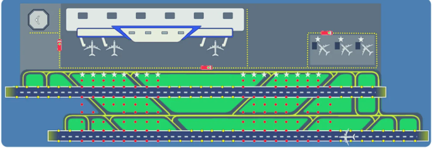
the subnetworks and the sink. In this thesis we opt for the opportunistic use of the airport service vehicles in regular duty as relay nodes. This type of mobile emissary node is better known in the telecommunications field as Mobile Ubiquitous LAN Extension (MULE). By opportunistic we imply that the service vehicles will keep their normal schedule and trajectory, and the subnetworks will need to exploit any moment of contact with them to forward data to the sink. A particular characteristic of the MULEs in our application is that they move along predefined trajectories indicated as service traffic roads in the airport. This implies the need for a data routing strategy to be used within each subnetwork in order to transfer the data collected by each sensor node to the ones located by the side of those roads. In this thesis, we call those nodes subsinks. Note that the communication scheme based on MULEs fulfills one of the main demands for the deployment of systems in airports, which is to keep the interference with the regular operations little or null. Figure 1.2 illustrates the proposed solution.
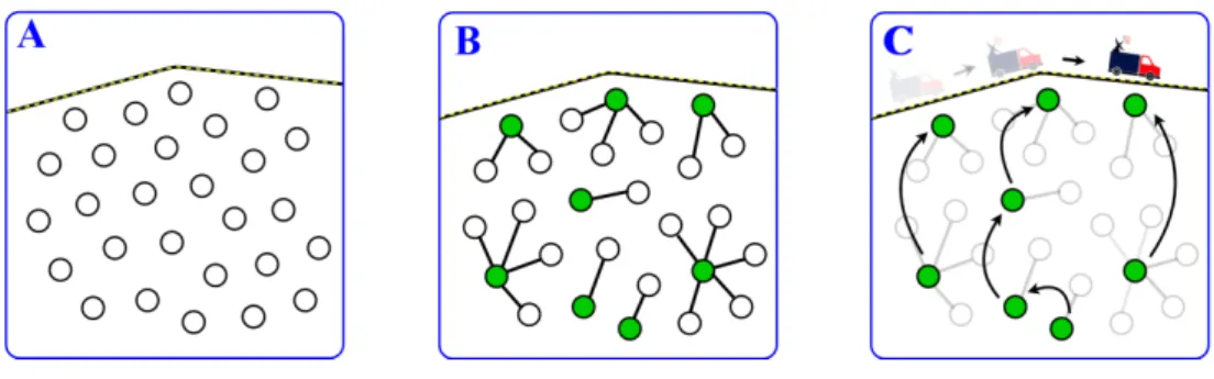
Figure 1.2: Proposed WSN-based monitoring solution. Sensor nodes ( , ) are suitably placed over green areas, by the side of runways and nearby parking spots to monitor environ-mental, safety-oriented and operational variables, respectively. Data MULEs ( ) doing regular tours occasionally pass by the side of the subnetworks making contact with the sub-sinks ( ). Along their trajectory and without stopping, the MULEs collect data from the subnetworks and move on with their duties. The data is delivered by the MULEs at the sink (e.g., the control tower ) also opportunistically during the journey.
It is important to remark that this research idea was submitted for evaluation at four airports of different size (Castres-Mazamet, Montpellier, Perpignan, and Toulouse-Blagnac). All of them confirmed the pertinence of the proposed monitoring system and acknowledged a clear operational value on it.
1.3.1
Supporting communication technologies
In this section we explain our selection of short- and long-range communication technologies for the transfer of non-critical (environmental and operational) and critical (safety-oriented)
data in the proposed system. We start by discussing the predominant communication tech-nologies nowadays and then we proceed with our selection.
Prevalent short-range technologies. Currently, the most popular alternatives for
short-range communication are the IEEE 802.11, 802.15.1 and 802.15.4 standards, often referred to as WiFi, Bluetooth and ZigBee, respectively [20, 21]. IEEE 802.11 is intended for devices transmitting at relatively high data rate which have either wired power supply or access to frequent battery reload [20]. IEEE 802.15.1 and IEEE 802.15.4 are better suited for cases where the nodes have limited energy supply. The energy spent both during transmission and reception is about 1/4 of that of 802.11 [22]. IEEE 802.15.1 allows a higher data rate than IEEE 802.15.4, but the latter has a considerably greater communication range. More precisely, the maximum communication range of IEEE 802.15.1 is only 10 m compared to 100 m for IEEE 802.15.4 [20]. The maximum communication range of IEEE 802.11 and IEEE 802.15.4 is similar.
Although the three technologies have been implemented in a number of studies, IEEE 802.15.4 has been notably the preferred choice for WSN [23]. This is thanks to the fact that it offers a relatively large communication range at a low power demand, characteristics that fit well most WSN applications [20].
Prevalent long-range technologies. Currently available long-range technologies can be
classified into two main groups named Cellular and Low-Power Wide Area Network (LPWAN) [24]. LPWAN technologies can in turn be subdivided into two groups: the ones using licensed mobile frequencies (LPWAN-L) and the ones using unlicensed ISM5bands (LPWAN-ISM) [26]. Cellular technologies (e.g., 2G, 3G, and 4G) provide high data rate long-range communication at relatively high energy spent [24]. A practical example of use of this technology is in mobile phones, which allow transfer of documents, web navigation and real-time video transmission, among other various functionalities, mostly supported on 3G and 4G, but require the user to recharge the battery about every day. The operation of this technology is conditioned to the availability of cellular coverage in the target region, which is often the case in most urban areas, but rather unusual in many rural, isolated or less populated places [27, 28].
As their name suggests, LPWAN technologies are specially conceived for applications re-quiring long-range communication at low energy spent. The moderate energy consumption is achieved at the expense of lower data rate than in Cellular technologies. In particular, LPWAN-L technologies (e.g., LTE-M, NB-IoT) ensure that the frequency band is used only by authorized devices making part of the network, thus preventing external devices from interfering in the communication. These technologies are conditioned to the availability of
5ISM stands for Industrial, Scientific and Medical. ISM bands refer to a portion of the RF spectrum
originally reserved by the International Telecommunication Union (ITU) for those sectors. Over the years, these have become more crowded by short-range, low power systems like ZigBee, Bluetooth and Wi-Fi [25]
base infrastructure such as LTE antennas, infrastructure typically owned and managed by mobile operators [29], providing coverage in the target region of implementation. Since the expansion of this kind of infrastructure is costly, adaptations and tailoring of the network is rarely driven by the needs of one single customer, but rather by the trends in geographical distribution of the demand [30].
LPWAN-ISM technologies, on the other hand, use unlicensed parts of the spectrum to support communications. Unlicensed bands can be used by everyone without any specific authoriza-tion; thus, systems operating on these are prone to interference caused by external devices [31, 32]. However, they have the advantage that the user is not dependent on third party infrastructure, but is allowed to build his own private network and tailor it as desired. Sigfox and LoRa fall under this category. Apart from both using relatively low data rates, each adopts particular strategies to keep moderate the energy consumption. LoRa, for instance, implements an operational policy where the maximum data rate is decreased as the trans-mission distance is increased [33,34]. Sigfox, for its part, imposes greater limitations on the packet size [24]. On top of that, these technologies must respect duty cycle regulations that strongly limit the number of packets that can be sent per hour [34]. The above makes these technologies more suitable for scenarios in which the traffic is considerably low.
Selected technologies
• For non-critical data: IEEE 802.15.4 standard (ZigBee) + MULE. Non-critical data in the ASAS application comprises environmental and operational variables. Environmental data in our system is expected to be gathered by most of the nodes in each subnetwork. Contrary to current monitoring practices based on a single high-cost weather station, we rely on several measurements performed at a collection of nodes spatially dis-tributed over the airport. This monitoring approach is less sensitive to local factors such as variations in temperature or pollution due to the presence of clouds or the proximity to motorways, respectively. In addition, it allows for a wider scope of exploitation of the sensed data and provides greater degree of detail (e.g., in the construction of spatial analysis maps for the airport). Measurements of environmental variables are typically performed in a peri-odic fashion at rates up to 1 record per minute at some weather stations [35]. Operational variables on the other hand are planned to follow an event based monitoring scheme, checking events such as the use of different taxiways and parking spots. The frequency of registers would then depend on the intensity of the activities conducted at each airport.
Among the short-range technologies, IEEE 802.15.4 seems advantageous for us since it allows for a relatively large communication range at a low power demand. These two features fit well our ASAS application where the sensing field typically has an area in the order of tens of squared kilometers and the nodes are battery powered. Direct sending from each sensor
simplify data routing. LoRa, in particular, appears more interesting since it allows a greater packet size which better fits the needs for environmental and operational sensing which might involve multiple variables of interest. However, the policy of reduction in maximum data rate as a function of the transmission distance is a high impact factor in the ASAS application, where the farthest nodes would be placed at various kilometers from the sink. On top of that, various recent studies [36,37,33] have pointed out scalability issues in LoRA linked to a weak prevention of collisions. For instance, [38] reported less than 14% of successful receptions in experiments involving LoRa-based systems with 250 and 5000 devices. Thus, although LoRa’s official specifications indicate thousand of devices [39], the consequent compromise in quality and efficiency suggests that, at least for now, this technology might be reserved for applications with a moderate number of devices.
Based on the above discussion, our choice for non-critical data is to make the transfer in two phases: (i) sending of data from the sensor nodes to the subsinks at each subnetwork; and (ii) opportunistic collection of the data stored at the subsinks and further delivery at the sink by means of the MULEs. For the first phase, we opt for the IEEE 802.15.4 standard as short-range communication technology. This standard is most widely used in the 2.4 GHz (ISM) band at a data rate of 250 kbps and has a maximum packet size of 127 B [21]. Those characteristics fit well to the periodicity and type of information to be transmitted in our ASAS application. The data relay approach based on MULEs for the second phase is well suited for the non-critical data which is tolerant to delays.
• For critical data: LPWAN (e.g., LoRa). Critical data in the ASAS application corresponds to safety-oriented variables which are reported based on events. Examples of those are the presence of FOD on the runways and the surpass of a threshold in the tem-perature of the pavement of a runway. This type of register takes place with relatively low frequency in the system, but each time it requires quick notification of the control tower seeking for immediate reaction in order to prevent any incident.
Our choice for critical data is to perform direct sending through an LPWAN technology, which allows the fast notification of any threatening situation in the runways to the control tower. In particular, at this point, we favor LoRa based on the advantages mentioned in the discussion above. However, other LPWAN technologies may also suit the needs of the proposed monitoring system. Although we discarded LoRa for sending of non-critical data, it results suitable for sending of critical data since the transmission rate is considerably lower and just a few nodes are expected to be notifying a safety issue simultaneously.
. Remark: neither IEEE 802.15.4 which operates at 2.4 GHz, nor LoRa, which operates at 433/868 MHz in EU, 915 MHz in US and 430 MHz in Asia, interfere with the airports’ operations [6]. Radio communication between control facilities and aircraft takes place in the frequency range of 108 to 136 MHz [40].
1.3.2
Main challenges for WSN-based monitoring in ASAS
The materialization of the WSN-based monitoring solution described above presupposes the assembly of technical and technological elements inherent to various disciplines, those being: (i) moderate-size sensor nodes able to perform for extended periods without need for battery replacement; (ii) reliable communication technologies for short- and long-range transmission; and (iii) a proficient routing protocol focused on the efficient use of the time in contact between the subnetworks and the MULE.
Element (i) has been proven feasible in previous studies which have implemented sensor nodes with the desired characteristics (see e.g., [41]). Element (ii) has been thoroughly discussed and supported inSection 1.3.1. Having verified that the proposal is feasible in terms of the first two elements, we focus on the third element, the routing protocol. In this application, the design of such a routing protocol must take into account the following particularities of the problem:
• Broad class of subnetwork topologies: as illustrated in Figure 1.2, the subnet-works located at different zones of the airport are likely to present heterogeneous topolo-gies. Moreover, the presence of runways, buildings, fences, taxiway bridges, among other elements might contribute to this heterogeneity by prohibiting the deployment of individual nodes at some particular locations, leaving holes in the subnetworks. The routing protocol should be versatile enough to offer high performance independently of the topology formed by each subnetwork.
• Uncontrolled MULEs: the communication system is assumed to have no control on the behavior of the MULEs. The visits of the MULEs to the different subnetworks will then occur as part of the regular transition of service vehicles during ordinary operation. The MULEs are also not expected to stop near any subnetwork to facilitate the collection of all stored data. Hence, the routing protocol should implement a convenient strategy for the transfer of the data gathered at each node to the MULE, making efficient use of the time in contact with it.
• Nodes with limited lifetime: in order to remove the limitations derived from the need of wire installation discussed in Section 1.2, we rely on battery-powered sens-ing devices. Since most of the data is expected to be transferred ussens-ing short-range communication, we envisage the use of application based sensor nodes such as TelosB [42] or MICAz [43] which come equipped with IEEE 802.15.4 (ZigBee) compliant RF transceiver. Nodes of this type run on two AA batteries with a nominal initial load of 18720 Joules [44], providing an expected battery lifetime of 1 to 5 years depending on the usage. The energy supply is thus not a critical issue for us as in certain (mostly military) applications where the nodes count with just 1 Joule as initial battery load.
Nonetheless, the elongation of the lifetime of the nodes translates into maintenance cost savings for the airport and thus, must be pursued. The routing protocol should then pursue an efficient use of the sensor nodes in their role as data receivers and forwarders. • Nodes with limited communication range: as a way to preserve the battery of nodes and prevent congestion issues, we privilege short-range communication for the transfer of all non-critical data (which as said before, is expected to be the large majority of it). The routing protocol should be able to integrate these communication constraints into the data transfer scheme.
• Need for self-organization: the proposed system is expected to embrace multiple subnetworks located at diverse areas of the airport. A straight way to guarantee the functioning of every subnetwork, regardless of its remoteness to the control center is to provide them with the ability to self-organize. This avoids the need for intense data transfer to a central coordinator node, and helps to keep low the acquisition cost of the solution by allowing some nodes (those not involved in safety-oriented monitoring) to be equipped with just short-range communication technology. The routing protocol should thus allow the configuration of each subnetwork for data transfer, based only on local interactions of the sensor nodes.
• Connectivity based on failure-prone devices: communication in WSNs inher-ently depends on the proper functioning of the nodes, which permaninher-ently perform as data forwarders. Hence, the loss of one node (e.g. due to failure or battery depletion) might leave multiple reliant nodes unable to send their data to the sink. Under this type of situation, the routing protocol should be able to opportunely react and pro-vide alternative paths to keep the network functioning. The protocol should be able to achieve this in a decentralized manner, following the ideas presented in the previous paragraph that motivate self-organization.
1.4
Organization of the manuscript
The remainder of this manuscript is structured as follows:
Chapter 2
. Routing protocols for WSNs: state of the art
As explained inSection 1.3.2, this thesis focuses on the construction of the routing protocol that would serve as the base of the proposed monitoring system. This chapter presents a literature review on routing protocols for WSNs with emphasis on four families of protocols that might result of particular relevance in the development of our method: (i) flat routing, (ii) cluster-based routing, (iii) routing in settings involving MULEs, and (iv) routing based on advanced optimization techniques. A detailed analysis of the protocols in those categories
allow us to identify useful techniques that could be exploited within our method and build up a list of research gaps, various of which are bridged in this thesis. This chapter extends our work published in the proceedings of the International Workshop on Communication Technologies for Vehicles (2018) [45].
Chapter 3
. WSN for ASAS: modeling and initial solutions
This chapter presents our first steps in the modeling and resolution of our WSN routing problem. There we implement and evaluate the two routing protocols from the literature, devised for settings involving MULEs, that better match our routing context and our selection of technologies. We compare the two protocols through computer simulation in OMNeT++. The results lead us to conclude on the ability of one of the two protocols to provide optimal solutions when the subnetwork has a regular grid-like topology, and open the discussion on the need for the development of a more sophisticated method able to deal with a more general class of subnetwork structures. This work was published in the proceedings of the International Conference on Ad-Hoc Networks and Wireless (2019) [46].
Chapter 4
. Advanced routing based on Ant Colony Optimization
Following the conclusions ofChapter 3and motivated by the large class of subnetwork topolo-gies that may arise in the ASAS context, in this chapter we undertake the construction of a protocol able to provide high quality routing solutions for a general class of subnetwork topologies. The proposed protocol is founded in the Ant Colony Optimization technique, which provides a general framework for the optimization of multiple objectives of perfor-mance of the subnetwork in a distributed manner. We name this protocol ACME, standing for ACO-based routing protocol for MULE-assisted WSNs. ACME is designed to select the subsink that each node must use as gateway to reach the MULE during an opportunistic visit to the subnetwork, and also the multi-hop path that each packet must follow from its source node to its gateway subsink. In this chapter, we model the routing problem as a multi-objective optimization task where the conflicting objectives of minimization of total path length and minimization of total subsink imbalance are considered as main targets. The minimization of total number of retransmissions is considered as a secondary, optional target. A thorough description of ACME and several technical implementation details are provided along the chapter.
Chapter 5
. ACME’s performance assessment
This chapter presents the computational experiments carried out to validate our Ant Colony based routing protocol, ACME. The experiment is split into three parts addressing the following aspects: (i) the ability of the protocol to provide high quality solutions for a variety
of subnetwork topologies when only the total path length and the total subsink imbalance are optimized; (ii) the impact on performance of adding the minimization of total number of retransmissions as a third objective of optimization; and (iii) the comparison between the efficiency in the interactions with the MULE achieved by ACME and that offered by the best performing routing protocol fromChapter 3. Our computational experiments in OMNeT++ show ACME’s ability to provide high quality solutions for a general class of subnetwork topologies and its suitability for application in real life ASAS instances.
Chapter 6
. Conclusions and future research
This chapter summarizes our work, contributions and scientific production, provides our general conclusions and presents some promising research lines for future development.
Chapter 2
Routing protocols for WSN:
state of the art
The chapter in brief
This chapter presents a literature review on routing protocols for WSN. The review is divided in two main sections, each corresponding to one family of protocols of particular relevance for the development of this thesis. InSection 2.1, we first discuss flat routing protocols where all the nodes have equal roles and functionality [47, 48]. While simplistic, those protocols might be valid solution approaches for our problem, or at least, serve as the base of a more sophisticated approach, if required. In Section 2.2, we discuss cluster-based routing, where the nodes are given responsibilities for the data forwarding process based on a specified hierarchical structure [49, 50]. Although most of the protocols found in this category do not explicitly consider MULEs, it is possible to find a strong affinity between them and our problem if we see the subsinks as a special type of node used to convey the data from groups of nodes to the MULE. Then, in Section 2.3 we move on to routing in settings explicitly involving MULEs. This section paves the road to a variety of concepts relevant to handle MULE specificities, but are naturally neglected by most of the studies discussed in Sections
2.1and2.2. The major part of studies covered up toSection 2.3propose systems of rules which are relatively simple from the perspective of current optimization techniques. In Section 2.4
we study more sophisticated routing protocols based on advanced optimization methods such as Ant Colony Optimization [51], Bee Colony Optimization [52] and Genetic Algorithms [53].
Section 2.6 wraps the section out with a synthesis on the topics discussed, the key ideas to keep in mind for next chapters and the open challenges for routing in S-WSN.
Contents
2.1 Flat routing . . . . 19 2.2 Cluster-based routing . . . . 24 2.3 Routing in settings involving MULEs . . . . 35 2.4 Routing based on advanced optimization techniques . . . . 39 2.5 General synthesis and main takeaways . . . . 43 2.6 Open research challenges . . . . 46
2.1
Flat routing
• Flooding: this is one of the simplest and oldest routing protocols one could find in the literature. Some of the earliest allusions to it could be found in [54] and [55]. Differently from most modern approaches, Flooding does not involve routing tables. Indeed, it departs from the idea that nodes are unaware of identities and locations. As its name suggests, what this strategy proposes is that every time a node has some information to share, it is propagated through the whole network until it reaches the interested destinations. To achieve that, the sender node broadcasts packets to its neighbors which repeat this process by broadcasting the packet to their neighbors as well; the process is repeated until all nodes in the network have received the packet. Any node will drop a packet that has reached a predefined maximum number of hops. The procedure is illustrated inFigure 2.1.
Figure 2.1: Flooding protocol.
The main strengths of this protocol are its simplicity and the low expectancy of a packet not reaching its destination. Those come at the cost of three major drawbacks: (i) most of the nodes receive several copies of each message, (ii) some nodes sense overlapped areas and thus send similar information to their neighbors, and (iii) energy consumption is disregarded. These three issues are well known in the literature by the name of implosion, overlap and resource blindness [47, 56]. As will become manifest throughout this survey, implosion and resource blindness have been addressed by almost every routing protocol proposed afterwards. Overlapping, on the other hand, is not addressed by various popular routing protocols (e.g., GAF [57] and RPL [58], which will be examined later). However, one could argue that some data aggregation scheme could be used on top of most routing protocols. Most of the protocols that explicitly take this issue into account lie in the category of cluster-based routing, explored in detail inSection 2.2.
them [54] . As a direct positive effect of this change, the implosion is reduced. However, it has been discussed that this strategy implies an important increment in the latency and a relatively high chance of the packets not reaching a suitable destination [59] as a consequence of the random selection of the next hop. The procedure is illustrated in Figure 2.2.
Figure 2.2: Gossiping protocol. The values p1, . . . , p4 denote probabilities of selection as a
next hop for the packet.
• Sensor Protocols for Information via Negotiation (SPIN): instead of a single protocol, SPIN [54, 56] embraces the family of protocols SPIN-PP, SPIN-EC, SPIN-BC and SPIN-RL. Briefly said, all four protocols depart from the idea of Flooding and work upon the concept of negotiation to overcome the issue of implosion. Negotiation consists of each node notifying its neighbors about the availability of some data before actually sending it, and then moving forward with the transfer only to those neighbors which reply with a data request. This mechanism, in turn, indirectly mitigates resource blindness by preventing much of the communication overhead related to duplicate packets.
The authors of SPIN also claim to resolve the issue of overlapping. To support this, they assume that the nodes are able to form a compact representation of any sensed data composed of named elements, that could be then used during negotiation instead of the original data in full representation. Thereby, upon receiving an advertising packet containing this compact description of the available data, a node must be able to indicate which pieces of the data it is interested in obtaining. However, in practice, it is not clear how most forms of sensed data sensed (e.g., sound signals or images) could be represented by a collection of named elements for use during the negotiation. This practical limitation of SPIN was also noted by [60]. Despite the aforementioned limitation, SPIN offers improved performance than Flooding and Gossiping thanks to the mitigation of implosion and resource blindness.
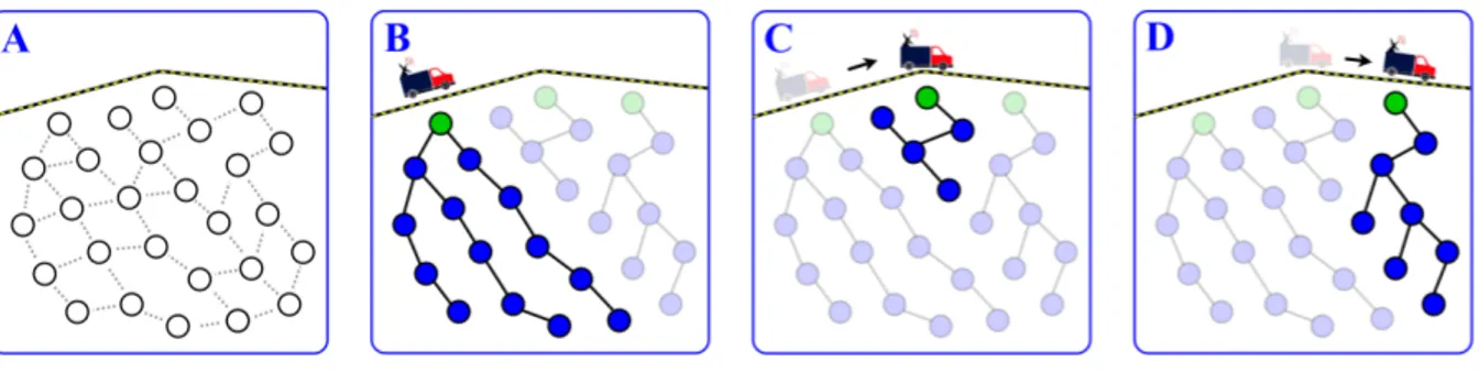
• Directed Diffusion: in contrast to the three previous protocols, Directed Diffusion [61, 62] considers a sink which occasionally requests specific data through query messages called interests. The interests are propagated through the network using flooding until they reach a node with matching event records. Such a node is called source. A characteristic that differentiates this from most other WSN protocols is the assumption that interests are
persistent, meaning that if a source has information relevant to the sink, then this last will be interested in repeated measurements from that source for some period of time. The network exploits this extended communication scheme by progressively improving the path while the sending of records is performed. To achieve this, the sink puts a fixed period of validity to each interest it delivers, and keeps extending the lifetime of interests only on the paths through which the event records are taking less time to be received. The interests thrown on the longest paths are thus left to expire and the frequency of traffic is progressively raised upon request of the sink.
In Directed Diffusion the network progressively learns how to efficiently route messages be-tween a particular source-sink pair. This type of strategy is especially useful when the interaction between a source and a sink is expected to last for a sufficiently long time such that the network is able to amortize the cost of finding efficient paths during their period of use. The next protocol in this revision presents an alternative for situations where such an interaction is expected to be brief.
• Rumor Routing: this protocol has basically the opposite assumption than Directed Diffusion. In Rumor Routing [63], the sink is presupposed to require just a small amount of data from a given source; thus, the authors of Rumor Routing argue that flooding every query throughout the whole network in order to find the best path may be more inefficient than delivering it by a non-optimal one. In rumor routing, the nodes observing an event dispatch a small number of a special type of packet called agent. Those advance through the network tracing a random path while updating the routing tables of the nodes they visit in order to let them know how to reach the source of that event. From a metaphoric perspective, the agents spread the rumor about the availability of information on some particular event and how to reach it. When a sink becomes interested in an event, it generates a query which starts to explore the network using a random walk as well. As soon as the query finds a node which already knows the path towards the matching event (thanks to the action of the agents), it redirects the query to the event directly through this path. The full sequence of links covered by the query from the sink to the source constituted the path finally used to transfer the information on the event.
• Geographic and Energy-Aware Routing (GEAR):in Flooding, Gossiping and SPIN, the information transfer is triggered by the record of new information at some sensing device. In Directed Diffusion and Rumor Routing it starts with a sink exhibiting interest for some type of event through queries. GEAR [64] addresses the case where the sink is able to specify the specific region of the sensing field for which it is interested in obtaining information. It was proposed as an improvement to Directed Diffusion where the interests are routed directly to the target region instead of flooding them through the whole network [64]. The main assumptions of this protocol are that the nodes are aware of the location and energy
level of themselves and their neighbors. To back up these assumptions, the authors rely on the availability of some positioning system (e.g., GPS, Galileo, GLONASS) and the occasional exchange of information between neighbors informing their energy level.
The routing of queries is done in two parts. In the first part, the query is routed from the sink to any node in the target region. To do so, each time a node receives an interest, it selects a neighbor as the next hop by minimizing the weighted sum of (i) normalized distance to the target region and (ii) normalized residual energy. The second part starts when the query reaches a node belonging to the target region. From that point and on, the query is disseminated using either a Restricted Flooding (RF) or a Recursive Geographic Forwarding (RGF) algorithm. RF works similarly to the regular Flooding strategy explained above, with the difference that only nodes within the target region forward the query. In RGF, the first node who receives the interest divides the target region into subregions and forwards the interest to one node in each of them. Each of the nodes that receive the query repeat the process of dividing and forwarding within their corresponding subregion. The process is repeated until every subregion contains only one node. At that point, every node in the target zone has received the query. Data dissemination to the sink is done identically as in Directed Diffusion. The authors recommend the use of RF when the nodes on the target region are sparsely deployed, and RGF for the contrary case of a dense coverage.
Certainly, the approach for query routing in GEAR might provide substantial energy savings compared to Directed Diffusion. Nonetheless, the way of identifying and specifying the shape of the subregions might be a difficult task that is somehow overlooked by the authors. The whole methodology and the simulations consider only the simple case of a rectangular sensing field and rectangular subregions which could be easily represented by a set of four coordinates. The general case with more complex shapes of both sensing fields and subregions is left unattended in the article.
• Geographic Adaptive Fidelity (GAF):this protocol is very similar to GEAR in many ways, including that GAF [57] also assumes that the nodes are provided with a positioning system, and also that it splits the sensing field into squared subregions. In this case, an im-portant condition is that the nodes in a given subregion are able to reach all the nodes within the adjacent subregions with a single hop. Under these two assumptions, the functioning of GAF is quite simple; within each subregion, the radio system of only one node is kept on at each time (active node), and the radio system of the others is turned off (inactive nodes). In addition, GAF considers nodes positioned at the same subregion as equivalent in terms of cost of packet routing. Thus, if the nodes within each subregion alternate the role of active node, the lifetime of the network results prolonged compared to a setting where the radio system of all nodes is kept on permanently. The role of active node within each subregion is periodically rotated, selecting at each time the node with highest residual energy.
Although the idea of strategically switching off some nodes from time to time might be bene-ficial, the approach proposed in GAF reduces to deploying redundant nodes over the network in order to obtain a longer average node lifetime. This, of course, comes at considerably larger acquisition costs, which might limit the scope of the protocol.
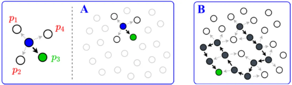
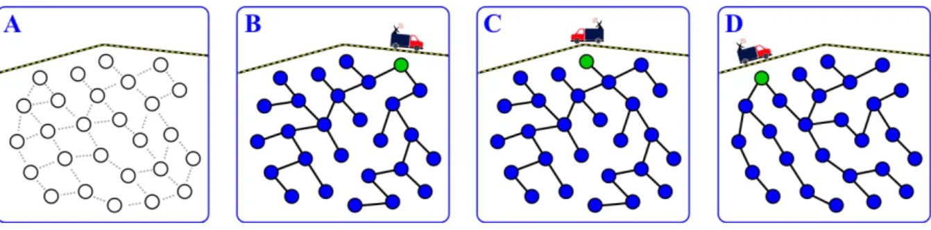
• Routing Protocol for Low-power and Lossy Networks (RPL): inspired by the classical Dijkstra’s algorithm [65], RPL [58] provides a method to build a shortest path tree, commonly named, a Destination Oriented Directed Acyclic Graph (DODAG) [66,67] which is typically rooted at the sink. The protocol works in a purely distributed manner and does not depend on positioning systems. Moreover, RPL is standardized by the Internet Engineering Task Force (IETF) group since 2012 [58]. Naturally, it is an ideal choice in terms of path length for networks with a single, fixed sink. Thereby, it has been pointed by some authors as a predominant routing protocol for the Internet of Things (IoT) [68].
In RPL, the paths from all the nodes to the sink are built simultaneously as follows. The whole procedure is supported in a special type of packet called DIO (standing for DODAG Information Object). Each time a node sends a DIO, it specifies its current lowest cost to reach the sink. For the sake of exposition, let us consider a cost expressed in terms of number of hops. The algorithm functions for any generalized cost function which might include the energy, distance or any other feature of interest. The procedure starts with the sink storing a cost of 0 and all the other nodes storing a cost of ∞. The sink broadcasts a DIO which is received by its neighbors. Then, each neighbor compares its current cost with the one it would have if it adopts the sink as its next hop. If the proposed cost is convenient, the neighbors of the sink adopts it as their parent (i.e., as next hop to reach the sink). Next, each of the neighbors of the sink repeat the process by broadcasting a DIO with their new cost to reach the sink. Their neighbors, in turn, compare their current cost to see if it is convenient for them to adopt the corresponding sender of the DIO as a parent, and if so, they proceed accordingly. The procedure is repeated multiple times until all the nodes are attached to the DODAG. The resulting graph is a tree where every node has a single path to reach the sink, which happens to be the shortest path connecting them. Thereafter, each node uses the routes obtained by the algorithm to transfer data to the sink. The only information each node needs to store is the ID of its parent. The procedure is illustrated inFigure 2.3.
2.2
Cluster-based routing
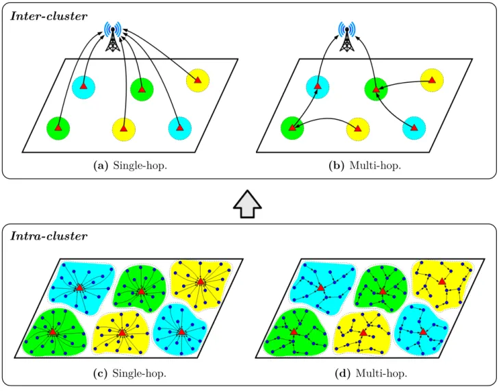
Cluster-based protocols constitute one of the main streams in WSN routing. Several surveys have consistently appeared over the last 15 years to report progress in this specific direction (see, e.g., [69, 70, 71, 72, 73]). The base idea of clustering is to arrange the sensor nodes by groups and then split the process of communication with the sink into three phases: (i) transmission from the cluster members to a cluster-specific leader node called cluster head (CH); (ii) aggregation of the data from the different cluster members at each CH; and (iii) transmission of the aggregated data from the CHs to the sink. Both, phases (i) and (iii), can be done either by single-hop or multi-hop routing (seeFigure 2.4).
(a) Single-hop. (b) Multi-hop.
(c) Single-hop. (d) Multi-hop.
Intra-cluster Inter-cluster
Figure 2.4: Cluster-based routing schemes. Clusters specified by the colored shades. Bottom frame: ways to transfer data from the sensor nodes ( ) to the cluster heads ( ). Top frame: ways to forward the data to the sink. Both (a) and (b) are are compatible with (c) and (d).
Clustering-based routing emerged as an alternative to direct transmission (single-hop com-munication between the nodes and the sink) and multi-hop routing, seeking for an extended network lifetime [74, 75]. The postulate is that clustering might help to achieve a more
homogeneous power consumption over the network than in multi-hop routing and, strongly relying on significant reduction of the total transferred data thanks to the aggregation at the CH level [76], it might also lead to lower energy consumption per node than in direct transmission.
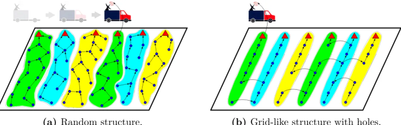
As briefly mentioned in the introduction of this chapter, there are some similarities between the arrangement of sensor nodes adopted in this thesis and the one typically used in cluster-based routing. Following our decision to work with multi-hop routing (see Section 1.3.1), each of our subnetworks could be seen as a cluster-based system where the subsinks play the role of CHs and groups of sensor nodes are assigned to them (seeFigure 2.5). Of course, some differences between the two settings are immediately noticeable. It stands out, for instance, the fact that our subnetworks need to communicate with a mobile device while the sink in cluster-oriented studies is regularly set fixed. In addition, in our problem the role of subsink comes implicit with the relative position of each sensor node to the pathway followed by the MULE, while cluster-based protocols involve the selection of the CHs. In spite of these differences, it could be worth taking a look at the cluster-based protocols proposed in the literature and check if we can find some ideas for our method. Thus, the remaining of this section is dedicated to the examination of various papers in cluster-based routing.
(a) Random structure. (b) Grid-like structure with holes.
Figure 2.5: Parallel between our ASAS setting and that of cluster-based routing. In analogy to Figure 2.4, the groups of sensor nodes ( ) assigned to each subsink ( ) are indicated by colored shades. Each subfigure represents a single subnetwork. The random and grid-like structures are used for the sake of exposition.
Overview of existing protocols
• Low Energy Adaptive Clustering Hierarchy (LEACH):borrowing ideas from clus-tering algorithms in various contexts (see details in [77]), LEACH [78] is acknowledged by various authors [79,80,81] as the first energy-efficient clustering protocol for WSNs. Its base idea is to periodically rotate the nodes that play the role of CH, seeking for a homogeneous energy dissipation over the network in the long term. The protocol involves a set-up phase where the clusters are formed, and a steady-state phase where the data is collected by the
![Figure 1.1: Monitoring solutions currently in use. Pictures (a), (b), (c), (d), (e) and (g) retrieved from [ 17 ], [ 12 ], [ 14 ], [ 15 ], [ 14 ] and [ 17 ], respectively.](https://thumb-eu.123doks.com/thumbv2/123doknet/2225485.15402/16.892.92.795.110.917/figure-monitoring-solutions-currently-use-pictures-retrieved-respectively.webp)