T
T
H
H
È
È
S
S
E
E
En vue de l'obtention du
D
DO
OC
C
TO
T
OR
RA
AT
T
D
D
E
E
L
L’
’U
U
NI
N
IV
VE
E
RS
R
SI
IT
TÉ
É
D
DE
E
T
T
OU
O
UL
L
OU
O
U
SE
S
E
Délivré par l'Université Toulouse III - Paul Sabatier Discipline ou spécialité : Science et Génie des Matériaux
JURY
Prof. Christophe Laurent, Université Paul Sabatier-Toulouse Dr. Annick Loiseau, UMR104/CNRS/LEM-Châtillon Prof. Ruediger Klingeler, Université de Heidelberg-Heidelberg
Prof. Bertrand Raquet, INSA, CNRS/LNCMI-Toulouse
Ecole doctorale : Sciences de la Matière Unité de recherche : Institut Carnot- CIRIMAT
Directeur(s) de Thèse : Dr. Emmanuel Flahaut, Dr. Anne-Marie Galibert Rapporteurs : Dr. Annick Loiseau, Prof. Ruediger Klingeler
Présentée et soutenue par Petar LUKANOV Le 19/11/2010
Titre :
Synthèse de nanotubes de carbone remplis et de nanoparticules encapsulées dans des coques de carbone pour applications biomedicales.
Title :
Synthesis of filled carbon nanotubes and carbon encapsulated nanoparticles for biomedical applications.
To my parents Maria and Rumen (За мойте родители Мария и Румен) To my sister Anna (За мойта сестра Анна) To my grandmother Kirilka (За мойта баба Кирилка)
And in memory of my grandfather Pesho
Acknowledgements
First and foremost I would like to thank my two supervisors Dr. Emmanuel Flahaut and Dr. Anne-Marie Galibert for accepting me as a fellow in CARBIO network and also for their invaluable assistance, support and time given in the preparation of this thesis.
I would like to thank Dr. Brigitte Soula for her advises and help in my experimental work and during the period of writing of my PhD manuscript.
I wish to acknowledge Dr. Rüdiger Klingeler the CARBIO network coordinator, for giving me chance to work in one of the best Laboratories in Europe (Leibniz Institute for Solid State and Materials Research-Dresden) during my secondment. Also I thank him for giving us the best conditions for working during these 3 years for what all PhD students can only dream.
I wish to acknowledge Dr. Philippe Tailhades, Professor Alain Peigney, Dr. Christophe Laurent and all Nanocomposites Nanotubes de Carbone team: Dr. Alicia Weibel, Dr. Julien Gurt, Guillaume Droval, Floriane Bourdiol, Christophe Guiderdoni, Anthony Pavia, Florent Seichepine and Dr. Cyril Tinguely for giving me the best ambiance and conditions in the lab during my PhD.
I wish to acknowledge Prof. Ivan Nedkov the head of the team “Microwave magnetics” in IE-BAS (Bulgaria) and to all my colleagues from this laboratory for giving me the start in the science and the great possibility to be part of their team in the period 2004-2007
I would like to thank all the people from Common Service of microscopy in University Paul Sabatier (TEMSCAN) and especially for the help of Lucien Datas who made the best images for my samples.
I would like to thank all my colleagues and friends from CARBIO network (see the photo) for the best CARBIO workshops in my life, the best professional collaboration and also for the big fun during my PhD.
I wish to acknowledge my girlfriend Dr. Nadia Bouhalli for helping me in the worst moments during my PhD and for giving me hope and power to continue to the end.
I would like to thank my best friend (Dr.) Valentin Butoianu with who I spent the best crazy moments of my live in Toulouse and I’m sure I will never forget him.
The CARBIO Partners.
1st row from left: Anke Dürkoop, Anja Wolter, Brigitte Soula, Anna-Marie Galibert, Emmanuel Flahaut, Arthur Taylor, Yulia Krupskaya, Carmen-Michaela Tilmaciu, Constanze
Lamprecht, Elena Heister, Sara da Costa, Carla Tripisciano, Ewa Borowiak, Anna Steplewska, Vanessa Sanz Beltran, Vijay Anuganti
2nd row: Bob Sim, Ryszard Kalenczuk, Vera Neves, Rüdiger Klingeler, Petar Lukanov, Kamil Lipert, Matthias Lutz, Kai Krämer, Giuseppe Cirillo, Martin Sobik, Ferry Kienberger,
Title of the thesis:
“Synthesis of filled CNT and carbon encapsulated nanoparticles for medical applications” Abstract:
This work was performed in the framework of the European FP6 RTN CARBIO
(www.carbio.eu) project, aiming at exploiting the potential of multi- functional DWNT and
Carbon encapsulated metal nanoparticles for biomedical application, in particular to act as magnetic nano-heaters (cancer treatment by hyperthermia) or drug – carrier systems.
To achieve these goals, DWNT have first been synthesised by catalytic chemical vapour deposition (CCVD) of a H2-CH4 mixture over (Mg, Co, Mo)O catalysts.
In order to fill the empty cavity of DWNT with magnetic materials, the tips of the tubes have to be opened. The opening of DWNT was performed in different conditions using wet chemistry routes such as oxidation with HNO3, HNO3/H2SO4, KMnO4 or K2Cr2O7 or dry
routes involving air oxidation or microwave heating. Due to drawbacks of some of the opening techniques (sample coating with amorphous oxidation debris), we have developed extra purification methods such as NaOH washing, oxidation in air or microwave heating.
The filling of DWNT was performed using one-step (during the opening) or two-step (after the opening) methods in over-saturated iron (III) nitrate or iron (III) chloride solutions, in different conditions in order to assess the influence of stirring time, concentration and temperature. Control experiments of filling with uranium compounds were performed.
A second strategy that we have developed in this work was the direct CCVD synthesis of carbon-encapsulated Fe, Co, Co/Fe and Ni nanoparticles. The encapsulated nanoparticles have been synthesized with gaseous mixtures of H2/CH4 or N2/CH4, using different
MgO-based catalysts (Mg0.95Co0.05O, Mg0.95Fe0.05O, Mg0.95Co0.025/Fe0.025O and Mg0.95Ni0.05O solid
solutions). The obtained samples correspond for example to spherical and/or oblong carbon-encapsulated Co nanoparticles with size distribution 6-10 nm (60%) and 11-20 nm (40%). Oblong or spherical carbon-encapsulated nanoparticles were also observed with Fe and Co/Fe, with diameter within the range 1-10 nm (80%) and 11-30 nm (20%). The most promising material for hyperthermia application was found to be the carbon-encapsulated Co nanoparticles which showed the highest saturation magnetisation at room temperature (Ms) and the highest Specific Absorption Rate (SAR).
Key words:
Double- Walled Carbon Nanotubes (DWNT), Opening, Functionalisation, Purification, Filling, Nanoparticles, Magnetism, Hyperthermia
Notations and Abbreviation
………..………...9General Introduction
………....11Chapter I: Bibliographic studies
I.1. Structure and properties of carbon nanotubes
………..………..15I.1.1. Structure and properties
………..…………...15I.1.1.1. Structure………...………...15
I.1.1.2. Properties………..………..18
I.1.2. Applications
………..………20I.2. Synthesis of CNT
………21I.2.1. Arc-discharge synthesis
………...……….………….….21I.2.2. Laser ablation synthesis
………..………22I.2.3. CCVD synthesis
………..….….22I.3. Opening of carbon nanotubes
……….………..24I.3.1. Introduction………..………...…24
I.3.2. Methods for opening CNT
………..………...…...25I.3.2.1. Wet chemistry route………...…...…25
I.3.2.1.1. Opening by oxoacids………..………25
I.3.2.1.2. Opening by other oxidants ………...…..27
I.3.2.2. Dry route……….………..……….31
I.3.3. Secondary reactions during opening
……….…………...….……..32I.3.3.1. Functionalisation by oxidising treatments……….……33
I.3.3.2. Purification of CNT………..………...……...…37
I.3.3.2.1. Gas phase oxidation……….………37
I.3.3.2.2. Liquid route oxidation………..………...39
I.4. Filling of carbon nanotubes
………42I.4.1. In situ filling
……….……….……….…….43I.4.1.2. CCVD in situ filling………..……….……….……..45
I.4.2. Ex situ filling
………..………46I.4.2.1. Filling of CNT from sublimated materials………46
I.4.2.2. Filling of CNT from melted phases………...48
I.4.2.3. Filling of CNT from solutions………...……51
I.4.2.3.1. Main parameters for filling of CNT from solutions………...……52
I.4.2.3.2. Methods for filling from solution………...………54
I.4.2.3.2.1. One-step method………..……...54
I.4.2.3.2.2. Two-step method………...………56
I.5. Direct synthesis of carbon-encapsulated metal nanoparticles
………...…61I.5.1. Synthesis
………...………..…61I.5.1.1. Arc-discharge synthesis………....…61
I.5.1.2. CCVD synthesis………..………..…62
I.5.2. Structure and magnetic properties
……….………….…….….63I.5.2.1. Structure………...……….…...63
I.5.2.2. Magnetic properties……….… ……64
I.6. Medical applications of metal nanoparticles and carbon nanotubes
…...65I.6.1. Medical applications of metal nanoparticles
………...….……..65I.6.1.1. Magnetic targeting for drug and gene delivery………....…65
I.6.1.2. Nanomagnetism and therapeutic hyperthermia………..………..……66
I.6.1.3. Magnetic Resonance Imaging (MRI) using magnetic nanoparticles………69
I.6.2. Medical applications of carbon nanotubes
……….…70Chapter II : Experimental Techniques
II.1. Synthesis of Double-Walled Carbon Nanotubes
………..……...…73II.1.1. Combustion synthesis ……….
………...………... 73II.1.2. CCVD synthesis of DWNT
…………...………...………….…73II.1.3. Extraction of carbon nanotubes or carbon-encapsulated metal
…………
nanoparticles
……….…….…74II.2. Sample preparation
………...……75II.2.1. Chemical oxidation
………..………...……75II.2.2. Dispersion
…………..……….……….………75II.2.3. Microwave treatments
………..………….…….76II.3. Characterization techniques
……….…...………76II.3.1. Chemical analysis
………..………...………….……76II.3.2. X-ray powder diffraction
………...………..……….76II.3.3. Specific surface area measurements
……….……….………76II.3.4. Zeta potential measurements
……….………...………...……77II.3.5. Electron microscopy
………..………….……79II.3.5.1.Scaning electron microscopy (SEM)………….………...79
II.3.5.2. Transmission electron microscopy (TEM)….………..……...……79
II.3.6. Atomic force microscopy (AFM)
………..………..………79II.3.7. Raman spectroscopy
...80II.3.8. Infra-red spectroscopy
...81II.3.9. Titrations
………..……….81II.4. Magnetic and heating properties
……….….…………..……81II.4.1. Magnetic characterizations
……….……….……81II.4.2. Hyperthermia
………...….82Chapter III: Opening of carbon nanotubes
III.1. Introduction
………..……83III.2. Methods for opening of CNT
………..………83III.2.1. One-step methods for opening and shortening of DWNT
…………..…84III.2.1.1. Wet chemistry route……….……….….84
III.2.1.1.1. Treatment by oxoacids………..84
III.2.1.1.3. Treatment by NaOH in melted phase…...………..…..94
III.2.1.1.4. Conclusion………...96
III.2.1.2. Dry route………..………...……….………..………...96
III.2.1.2.1. Oxidation in air………..96
III.2.1.2.2. Microwaves treatment………98
III.2.1.3. Conclusion………...………102
III.2.2. Two-step methods for opening and shortening of DWNT
…..……...102III.2.2.1. Treatment by thermal oxidation in air followed by oxidation by 3M HNO3 ..102
III.2.2.2. Treatment by conc.H2SO4/conc.HNO3 followed by oxidation by 3M HNO3 ..104
III.2.2.3. Conclusion………...105
III.3. Secondary reactions during one step opening
………...…106III.3.1. Acid group functionalisation and stability of
water/nanotubes suspensions
………..………..106III.3.1.1. Functionalisation by acid groups………106
III.3.1.1.1. Infra-red spectroscopy……….106
III.3.1.1.2. Titration of acidic functions……….……....………...107
III.3.1.2. Stability of aqueous suspension of CNT measured by Zeta potential………...………..110
III.3.1.2.1. Measure of the Zeta potential of suspensions of oxidised CNT by oxoacids….………...………..…111
III.3.1.2.2. Measure of the Zeta potential of suspensions of oxidised CNT (other oxidants)………...….…… ………...113
III.3.1.3. Conclusion………...……….114
III.3.2. Purification of CNT
……….……….115III.3.2.1. Purification by liquid phase oxidation………...115
III.3.2.1.1. Elimination of catalytic metal nanoparticles………...115
III.3.2.1.2. Creation of amorphous carbon………..119
III.3.2.2.1. Elimination of catalytic metal nanoparticles………...141
III.3.2.2.2. Removal of amorphous carbon………146
III.4.
Secondary reactions during two-step opening - elimination
of amorphous carbon
………...…...…148III.4.1. Methods………..………
148III.4.2. Results
……….……….………..148III.5. General conclusion
……….…..…151Chapter IV: Filling of DWNT from solutions
IV.1. Filling from solution during opening (one-step filling)
………..….153IV.2. Filling from solution after opening (two-step filling)
……….…..156IV.2.1. Short-time filling from solutions at 80°C
……….….…156IV.2.2. Room temperature long-time filling from solutions
………...…166IV.2.2.1. Solution filling
……….…166
IV.2.2.1.1. The influence of the pre-treatment on the filling yield ……….………...166
IV.2.2.1.2. The influence of the liquid media on the filling yield of . H2SO4/HNO3 pre-treated DWNT ………..………...170
IV.2.2.2. Solution filling of DWNT followed by reduction in H2 atmosphere………….175
IV.3. Filling from ferrocene
………...180IV.4. General conclusion
………...………...……182Chapter V: Direct CCVD synthesis of carbon-encapsulated metal
nanoparticles
V.1. Introduction
………..……185V.2. Preparation and characterization of Mg
1-xM
xO (M= Fe, Co, Ni, Co/Fe)
.
catalysts
………..………...…….186V.2.1. Combustion synthesis of of Mg
1-xM
xO (M= Fe, Co, Co/Fe or Ni)
………….
catalysts
………...…186V.2.2. XRD Characterization
……….…187V.3. CCVD synthesis and characterization of nanocomposite powders
…..188V.3.1. CCVD synthesis parameters
………..…188V.3.2. Characterization of nanocomposite powders
……….189V.3.2.1. Fe nanocomposite powders ………..189
V.3.2.1.1. Dwell temperature ………..……….…...191
V.3.2.1.2. Atmosphere of heating ramp, CH4 flow-rate and dwell time …………...192
V.3.2.2. Co nanocomposite powders…..……….195
V.3.2.2.1. Evaluation of carbon content for different dwell times…...196
V.3.2.2.2. Influence of the atmosphere of the heating ramp………..…198
V.3.2.2.3. Influence of the Co content in the catalyst powder...199
V.3.2.2.4. Influence of dwell temperature……….………...199
V.3.2.3. Fe-Co nanocomposite powders……….………200
V.3.2.4. Ni nanocomposite powders ………...………200
V.4. Characterization of extracted samples
………201V.4.1. Characterization of C-encapsulated Fe nanoparticles
………….……...201V.4.1.1. X-ray diffraction………201
V.4.1.2. Influence of the CCVD parameters on synthesis of Fe@C nanoparticles……….……..202
V.4.1.2.1. Influence of the type of atmosphere during the heating ramp………..…..202
V.4.1.2.2. Influence of the flow-rate of CH4 during different dwell times..……...…204
V.4.1.2.3. Influence of the flow-rate on the nanoparticles size distribution………...205
V.4.1.2.4. Influence of the flow-rate on the length and thickness of Fe-filled nanofibers...208
V.4.1.2.5. Influence of the flow-rate on Fe content and the yield of Fe@C nanoparticles...211
V.4.1.2.6. Influence of the flow-rate on the defects of the Fe@C structure……..….213
V.4.1.2.7. Influence of the flow-rate on the thickness of the carbon shells...214
V.4.2. Characterization of extracted carbon-encapsulated Co
nanoparticles
………..……….……...…219V.4.2.1. X-ray diffraction………....219
V.4.2.2. Influence of the CCVD parameters on the synthesis of Co@C nanoparticles...220
V.4.2.2.1. Influence of the flow-rate………...220
V.4.2.2.2. Influence of the heating rate…………...222
V.4.2.2.3. Influence of the dwell time………..222
V.4.2.2.4. Influence of the Co content in the catalyst powder…...………...…224
V.4.2.2.5. Influence of the dwell temperature ………...……...225
V.4.2.3. Conclusion……….………...…227
V.4.3. Characterization of extracted carbon-encapsulated Co-Fe
. nanoparticles
……….………...…….228V.4.3.1. X-ray diffraction……….228
V.4.3.2. TEM investigations……….…229
V.4.3.3. EDX analysis………...………...……230
V.4.3.4 Conclusion………...……231
V.4.4.Characterization of extracted carbon-encapsulated Ni nanoparticles
...231V.4.4. Conclusion
………...………..….23V.5. Magnetic characterizations and hyperthermia
………233V.5.1. Magnetic characterizations
………...…………..……233V.5.1.1. Magnetic characterizations of Fe@C nanoparticles…………...…………..…233
V.5.1.2. Magnetic characterizations of Co@C nanoparticles……….238
V.5.1.3. Magnetic characterizations of Co-Fe@C nanoparticles…………...…………239
V.5.1.4. Magnetic characterizations of Ni@C nanoparticles………...…………...240
V.5.1.5.Conclusion…….………...………...241
V.5.3. Hyperthermia
………..……...…241V.5.3.1. Hyperthermia of Fe@C nanoparticles………...242
V.5.3.2. Hyperthermia of Co@C nanoparticles ……….…….…245
V.5.3.3. Hyperthermia of Fe-Co@C nanoparticles ………248
V.5.3.4. Hyperthermia of Ni@C nanoparticles ……….……..…248
V.5.3.6.Conclusion………...…250
V.6. Relaxometry of Co-encapsulated nanoparticles
………..…………251V.7. Biocompatibility of Co-encapsulated nanoparticles
………….………..…252V.8. Conclusion
……….………255General conclusion and perspectives
………….….……….……….…257Notations and Abbreviation
AFM: Atomic force microscopy
BET: Specific surface area measurements (Theory of Brunauer, Emmett and Teller) CCVD: Catalytic Chemical Vapour Deposition
CNT: Carbon Nanotubes
Co@C: Carbon-encapsulated Cobalt nanoparticles CFs: carbonaceous fragments
DWNT: Double-Walled Carbon Nanotubes Fe@C: Carbon-encapsulated Iron nanoparticles
Fe-Co@C: Carbon-encapsulated Iron-Cobalt Nanoparticles HRTEM: High Resolution Transmission Electron Microscopy
ID/IG: Ratio between the intensity of D and G bands from Raman spectroscopy
IR: Infra Red
Ms: Magnetisation saturation
MWNT: Multi-Walled Carbon Nanotubes
Ni@C: Carbon-encapsulated Nickel nanoparticles ppm: parts-per-million
rpm: round-per-minute
PIXE: Particles Induced X-ray Emission RBS: Rutherford Backscattering
RT: Room temperature
SAR: Specific Absorption Rate SEM: Scanning electron microscopy SPM: Superparamagnetic
SWNT: Single-Walled Carbon Nanotubes td: Dwell time
TEM: Transmission electron microscopy Td: Dwell temperature
XPS: X-ray photoelectron spectroscophy wt.%: Weight percent
General introduction
This work was performed in the framework of the European FP6 RTN CARBIO
(www.carbio.eu) project, aiming at exploiting the potential of multi-functional CNT and
Carbon encapsulated metal nanoparticles for biomedical application, in particular to act as magnetic nano-heaters (cancer treatment by hyperthermia) or drug-carrier systems.
The objective of our investigations was to exploit the potential of multi-functional carbon nanotubes (CNT) for human medical applications with a focus on anti-tumour treatment-which allow targeted release of heat and/or drugs in cancer cells. The nano-devices (Fig.1) would act as magnetic nano-heaters, drug-carrier systems and temperature sensors for therapy and diagnosis at the cellular level.
Fig. 1: Functionalised Carbon Nanotube with different filling and biofunctional derivatization of the outer shell.
The use of carbon-wrapped nanocontainers has several advantages, particularly in medical applications. Firstly, due to the protecting carbon shell, the number of materials which can be used for applications without toxic adverse effects strongly increases. Secondly, the outer shell of CNT can be chemically modified, e.g., with cancer-specific binding agents in order to enable attachment to a given tissue, or penetration into specific cells.
Since the discovery of Carbon Nanotubes (CNT) in 1991 by Iijima this carbon material became one of the most interesting materials in the modern science due to their amazing and unique properties (chemical, electronic, optical, mechanical, magnetic, etc.).
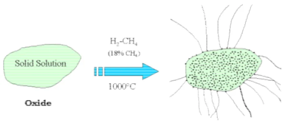
The basic material for our studies (raw Double-Walled carbon NanoTubes -DWNT) was synthesised in CIRIMAT using conditions developed by the "Nanocomposites and Carbon
Nanotubes Group". For the general case of the synthesis of DWNT, the catalyst Mg1-X(Co,Mo)xO was treated at 1000 °C in H2/CH4 atmosphere (18% CH4, 15 L/h).
In order to introduce different materials inside the empty cavities of DWNT they have to be opened. The opening of the closed as-made CNT was realised by wet or by dry routes. In the case of wet chemistry route opening, we compared the effect of oxidation by an oxoacid such as HNO3 at different concentrations (3M HNO3 or 15M HNO3) or by a mixture
of two oxoacids such as conc.H2SO4/conc.HNO3. We compared the effect of oxidation by two
other oxidants such as KMnO4 and K2Cr2O7 in solution in H2SO4. We studied the mechanism
of opening of DWNT by NaOH in melted phase. The oxidation and opening of CNT by heating in air is known as an efficient and easy method. We studied the opening of DWNT by air oxidation at 500°C. Based on the mechanism of air oxidation at high temperatures, we also investigated the opening of DWNT by using microwaves heating of powders. In most of the cases, due to secondary reactions, the opened tubes required secondary treatment in order to purify them. As a second step of treatment, the opened tubes were washed with 4M NaOH or with KMnO4/H2SO4, or they were oxidised by air or treated by microwaves.
We performed two types of solution fillings: filling of the tubes during the opening (One-step solution filling) or filling after pre-opening of the tubes (Two-step solution filling). The two-step filling was separated in two groups: short time solution filling where the time of treatment was up to 48h and long-time solution filling where the filling time was increased up to 33 days. The short-time filling was performed in two ways; by stirring at 80°C of suspension containing DWNT and Fe precursor (FeCl3.6H2O) or Uranium compound used for
a control experiment, and the second way of short-time filling was performed by treatment in autoclave using ferrocene as Fe precursor, dissolved in toluene.
A second strategy that we have developed in this work was the direct CCVD synthesis of carbon-encapsulated Fe, Co, Co/Fe and Ni nanoparticles. The encapsulated nanoparticles have been synthesized with gaseous mixtures of H2/CH4 or N2/CH4, using different
MgO-based catalysts (Mg0.95Co0.05O, Mg0.95Fe0.05O, Mg0.95Co0.025/Fe0.025O and Mg0.95Ni0.05O solid
solutions).
This PhD manuscript contains five chapters including: Chapter I- Bibliographic studies about properties, application, synthesis, functionalisation, opening and purification of CNT and also synthesis and medical applications of metal nanoparticles; Chapter II- Experimental Techniques including methods for synthesis of CNT and carbon-encapsulated nanoparticles, details about different techniques used for analysis and characterisation of samples; Chapter III - Opening of CNT including different methods (wet and dry methods), functionalisation and purification; Chapter IV- Filling of DWNT from solutions, by different methods for filling with iron or uranium. Chapter V- Direct CCVD synthesis of carbon-encapsulated metal nanoparticles, including different CCVD conditions for synthesis, magnetic characterisation, heating effect, Magnetic Resonance Imaging (MRI) and toxicity of carbon-encapsulated metal nanoparticles.
I.1. Structure and properties of carbon nanotubes
Since the discovery of Multi-Walled Carbon Nanotubes (MWNT) in 1991 by Iijima (Fig.I.1) [1] this carbon material became one of the most interesting materials in the modern science due to their amazing and unique properties (chemical, electronic, optical, mechanical, magnetic etc.). Just two years later, in 1993, a new huge effort has been done by Iijima, Bethune and co-workers who imaged tubular forms of carbon, called Single Walled Carbon Nanotubes (SWNT) [2, 3]. Great progress was made towards many applications, including for example: materials (energy storage, composites, etc.) or devices (probes, sensors, energy transports, memories, flat panel displays, etc.) [4].
Fig. I.1: TEM images of (a, b, c) the first reported multi-walled carbon nanotubes (MWNT) reported by Iijima in 1991 [1] and of (d) single-wall carbon nanotubes (SWNT) reported by
Iijima et al. in 1993 [2].
I.1.1. Structure and properties
I.1.1.1. Structure
Carbon nanotubes can be considered as rolled up graphene sheets forming one cylinder which is closed at the ends by half fullerene molecules (Fig.I.2) [5].
Generally, CNT can be described by their type of structure and by the number of walls. Based on the orientation of the tubes axis with respect to the hexagonal lattice, the structure of nanotubes can be completely described through its chiral vector C (Fig.I.2)
which is denoted by the chiral indices (n, m) and where a1 and a2 are the graphene lattice
vectors (Eq. I.1):
C = nx a1 + mxa2 (eq. I.1)
The chiral vector C joins two crystallographically equivalent sites of the nanotubes on the
graphene sheet (being the graphene basis [6] where a= |a1|=|a2| ≈ 2.49 Å).
Fig. I.2 : Schematic of a two- dimensional graphene sheet illustrating lattice vectors a1 and
a2 [6].
By rolling of graphite sheet in different directions, two specific nanotubes can be obtained: zigzag (m=0), armchair (n=m) and while both these types of tubes possess mirror symmetry, nanotubes with m≠n are chiral (Fig.I.3) [6, 7].
Fig. I.3: Roll-up of a graphene sheet leading to the three different types of CNT [7].
According to the number of walls, CNT can be separated in 2 groups: the first discovered “Multi-Walled“ CNT (MWNT) [1], the “Single-Walled” (SWNT) [2, 3]. On the border between SWNT and MWNT are Double-Walled Carbon Nanotubes (DWNT) which contain two concentric cylinders (Fig.I.4).
Fig.I.4: Models of (a) a MWNT, (b) a DWNT and (c) a SWNT.
I.1.1.2. Properties
The band structure of CNT is the most important factor to describe the conducting properties, which can be derived from the electronic structure of a graphene sheet [8]. Generally, one third of the SWNT are expected to be metallic, and the remaining two thirds to be semiconducting. By resolving the hexagonal-ring structure of the walls, it was shown that the electronic properties of SWNT depend on their diameter, the helicity [6] and the wrapping angle [9]. Experimentally, it was confirmed that an individual SWNT [10], a SWNT bundle [11] or a MWNT [12] behave intrinsically as a quantum wire because of the confinement effect in the tube. The metallic or semi-metallic nature of a MWNT is largely determined by the nature of its outer wall. It was observed that the high defect density in the structure of individual SWNT has a negative influence on their conductivity [13]. There are a number of reports on the resistance of nanotubes, but the lack of sample quality and purity makes them difficult to compare. When the measurement is carried out for purified SWNT ropes, the transport studies demonstrate ohmic contact, giving resistance as low as 20 kΩ at low temperature [14].
In a weak-magnetic field, nanotubes exhibit large diamagnetic and paramagnetic responses depending on the field direction, the Fermi energy, the helicity and the nanotube radius [15]. It was calculated that the gap band of SWNT changes under uniaxial and torsional strains [16].
Theoretical calculations and experimental measurements showed that the thermal conductivity for SWNT [17] and MWNT [18] ropes at room temperature is between 1800 and 6000 W/m-1K-1, whereas thermal conductivity of single MWNT was confirmed to be 3000 W/m-1K-1 [19]. Berber et al. [20] reported an unusually high value, λ ≈ 6600 W/m-1K-1, for an isolated (10, 10) nanotubes at room temperature, comparable to the thermal conductivity of a hypothetical isolated graphene monolayer or diamond.
Generally, the optical properties of SWNT can be understood from their band structure. The photoconductivity of individual carbon nanotubes was measured and it was found that they act as the channel of field-effect transistor (FET) upon infrared laser illumination [21].
The theoretical external specific surface area of CNT showed large values (50-1315 m2/g) as a function of their characteristics such as the diameter, the number of walls
and the number of nanotubes in a bundle [22]. Increasing the number of walls and diameter decreases the specific surface area of CNT (Fig.I.5).
Fig. I.5: Specific surface area of carbon nanotubes versus their diameter and number of walls [22].
One of the biggest advantages of CNT is their mechanical properties which are better than that of steel [13]. The elastic stretching properties of SWNT showed that they can be manipulated with large angle under high strain and no bond breaking was observed [13, 23]. The Young’s modulus (tube axis elastic constant) of a SWNT (1054 GPa) and a MWNT (1200 GPa) showed much higher values than those of a carbon fibre (350 GPa) or steel (208 GPa) [24].
Small radius, large specific surface area and the σ-π hybridization make CNT very attractive in chemical applications because of their strong sensitivity to chemical or environmental interactions. However, the fact that pristine CNT are insoluble in organic and aqueous solutions makes great limitation. Functionalisation can be used to modify the interface between the environment and the outer wall of CNT. The chemical activity of the tubes is focused on the defects in the structure or on their tips where the carbon atoms have some sp3 character. The carboxyl groups, present in pristine samples of CNT or obtained after oxidising treatments of pristine samples are usually the starting point of the functionalisation of the tubes. They can be used for further attaching molecules like for example glucosamine, which makes the tubes soluble in water [25].
I.1.2. Applications
Due to the need of material with extraordinary properties in the last years, the application of CNT has grown. Generally, the applications of CNT can be separated into three areas:
- for electronics- due to the nanometer size diameter and high electronic conductivity of CNT it was considered that nanometer-sized electronic devices containing CNT will be useful for downsizing circuit dimensions. Closed SWNT were used in producing electronic devices with four electrical contacts (SWNT-SWNT junction) [26]. Integration of multiple devices on a single chip allows constructing a nonvolatile random access memory (that functions like an electromechanical relay), an inverter and an AC ring oscillator [27, 28].
- for composite materials - with continued development in the synthesis and production of carbon nanotubes, composite materials containing nanotubes are a near-term application and will see innovations that take advantage of their special properties [29]. For example, composites made by deposition of conducting polymers onto MWNT can be used as
supercapacitor devices [30]. SWNT in poly (3-octylthiophene) polymer showed properties suitable for use in photovoltaic cells [31]. A donor-acceptor-type photovoltaic device with a heterojunction was fabricated with the addition of DWNT in the polymer layer, which improved the charge transport in the device [32].
- CNT for transport and storage of energy- SWNT, DWNT or MWNT have been successfully applied as high current electron source, supercapacitors [33], flat-panel displays, solar cells, Li ion batteries and thermoionic emitters [34]. In the close future CNT are planed to be applied also for space elevator [35]. It was shown that SWNT bundles can be used as a host for hydrogen storage by the physisorption mechanism [36, 37]. It has been also predicted that CNT can be able to store liquids as well as gases in the inner core through capillary effect improving metal hybrid batteries [38].
I.2. Synthesis of CNT
There are three methods for synthesis of carbon nanotubes: arc discharge, laser ablation and chemical vapour deposition -CVD (CCVD, for “Catalytic Chemical Vapour Deposition”).
I.2.1. Arc-discharge synthesis
The arc-discharge method was first successfully used for production of fullerenes developed by Krätschmer and co-workers in 1990 [39]. Graphite rod is evaporated by applying an AC voltage in an inert gas (He) to produce fullerenes. The evaporated anode generates fullerenes in the form of soot in the chamber, and a part of the evaporated anode is deposited on the cathode. In that cathode, Iijima identified, CNT [1]. Large-scale production of MWNT by arc-discharge has been achieved also in He gas [40, 41]. When a graphite rod containing metal catalyst (Fe, Co, etc.) was used as an anode with a pure graphite cathode,
SWNT were generated in the soot [2, 3]. By a hydrogen arc discharge method, it was also possible to synthesize high-quality DWNT (about 55 wt. % in the as-prepared product) using MWNT/CNF as a raw material (CNF = carbon nanofibers) [42]. In general the arc discharge method is more useful for the production of MWNT.
I.2.2. Laser ablation synthesis
The laser ablation is another method for synthesis of CNT using evaporation of carbon target by laser. The first laser ablation synthesis of SWNT was achieved in 1995 by the Smalley group [43]. Graphite composite target (C= 98.8 at.%) and catalyst of Co/Ni (1.2 at. %) were placed in a 1200°C quartz tube furnace with an inert atmosphere of 500 Torr of Ar and vaporized with a laser pulse. The metal particles catalyze the growth of SWNT in the plasma plume with diameter distribution between 1.0 and 1.6 nm, but many by-products are formed at the same time. In principle, arc-discharge method and laser ablation are similar methods, as both use metal graphite target to produce SWNT and both produce MWNT and fullerenes when pure graphite is used instead. Although laser ablation usually leads to much cleaner samples.
I.2.3. CCVD synthesis
CCVD (Catalytic Chemical Vapour Deposition) is the third method (or family of methods) for synthesis of CNT. The possibility to control the experimental conditions gives opportunity to optimize the process in order to produce high yield product with high quality. This technique is based on decomposition of a carbon-containing gas in the presence of catalytic metal nanoparticles. These nanoparticles can be obtained by decomposition of organometallic precursors [44], by reduction of a supported metallic precursor [45] or by selective reduction of a solid solution [46]. Numerous of parameters like temperature, reaction
time, composition of the gas or gas flow rate control the nature of the carbon product. At the beginning CNT have been synthesized by decomposition of acetylene [47, 48]. Later, other sources of carbon like methane [49], benzene [50], carbon monoxide [51] or ethanol also have been also used.
The team Nanocomposites and Carbon Nanotubes (NNC) in CIRIMAT developed the first synthesis of DWNT in high yield (1g of DWNT from 10 g of catalyst) by decomposition of a mixture of CH4/H2 using Co/Mo-MgO catalyst [52], with high selectivity (about 80 % of
CNT are double-walled, Fig.I.6).
Fig. I.6: (a) cross section HRTEM image of DWNT, (b) distribution of the number of
walls established from images of 96 CNT, inner (di) and outer (do) diameter distribution (c)
for 96 CNT and (d) for DWNT only [52].
The big advantage of this synthesis is that residual metal catalyst nanoparticles and MgO can be easily removed by hydrochloric acid washing without damaging the tubes [52]. Li et al. [53] synthesized DWNT from MgO impregnated by Co/Mo catalyst (from 2.5 to 5 wt. % of Co) in CH4/H2 atmosphere. The selectivity and the yield in this case are not given.
Flahaut et al. [54] reported the synthesis of DWNT starting from catalyst prepared from Al2-2xFe2xO3 solid solution. The CNT-Fe/Fe3C-Al2O3 composite was prepared at 1050°C
in H2/CH4 atmosphere and as a result about 65% of the CNT composite are DWNT. Liu et al.
[55] demonstrated the importance of the addition of Mo in the catalyst by increases the CNT yield. In this case Fe-Mo/Al2O3 catalyst was treated in Ar/CH4 atmosphere at 950°C. Single
It was also demonstrated that alcohol can be used as an ideal carbon source to prepare DWNT over alumina supported Fe-Mo catalyst at 800°C with high selectivity (95%) and high-purity [56]. DWNT with outer diameter in the range 1.5-3.5 nm and an average interlayer distance of 0.38 nm between the concentric tubes were observed. More recently, Yamada at al. [57] synthesized vertically aligned DWNT in Si/SiO2 substrate using Al2O3/Fe
catalyst by decomposition of acetylene. Forests of CNT with heights of up to 2.2 mm were obtained (with 85% selectivity of DWNT).
I.3. Opening of carbon nanotubes
I.3.1. Introduction
In general, two methods for filling of carbon nanotubes are known: filling during synthesis which is a single-step procedure (in situ) and filling after opening of CNT (ex situ) which is the most versatile route because it is able to insert nearly any kind of materials in CNT [58]. The very first step for ex situ filling of nanotubes is dedicated to the opening of their tips, which can be achieved using two main ways [58]. Both have been documented a long time ago and consist in using thermal treatments in oxidizing gas atmosphere (air, O2, O3
[59], CO2) or liquid reactants, typically, supercritic water or oxoacids such as HNO3, mixture
of HNO3 and H2SO4 or HClO4 [60]. Some other oxidants such as KMnO4, H2O2 [59],
K2Cr2O7, OsO4, OsO4-NaIO4 [61] or activation with KOH [62] are also used. Methods for
opening CNT such as mechanical ball milling opening [63] or electrochemical opening [64] can also be used. The liquid phase oxidation tends to generate residues that may more or less cover the CNT, hindering characterisation or filling. In this regard, gas phase oxidation may be preferred.
The methods used for opening of CNT may also be used for purification, functionalisation and shortening of CNT.
Considering the high inertness of the graphene lattice towards chemical oxidation, opening normally occurs at the location of structural defects or high strain. However, a major discrepancy in the behaviour of MWNT versus SWNT upon oxidation treatment for opening purpose is that the former are able to open from the tips only, whereas SWNT are able to open from the tips and side wall. In MWNT, the complete opening of the wall structure is almost impossible, except at the tip region where pentagons are present. Once CNT have been opened, their opened ends possess extra interesting properties and often additional potential applications. Compared to the closed CNT, open-ended CNT have higher conductivity and much improved field-emission properties [65]. Open-ended SWNT were found to be much more active centres for the N2 adsorption and the activation of the N-N bond [66]. Liu et al.
[67] and Heu et al. [68] studied the modification of the geometrical structures and chemical shifts of open-ended SWNT using density functional theory.
In general, theoretical work leads to the conclusion that the open-ended tubes show different reactivity properties than the raw closed tubes mainly due to the differences of their electronic structure [69].
I.3.2. Methods for opening of CNT
I.3.2.1. Wet chemistry route
I.3.2.1.1. Opening by oxoacids
The oxidation of CNT by oxoacids like for example by HNO3, HClO4 or a mixture of
HNO3 and H2SO4 have many advantages such as low operation temperature and high
selectivity at the tips.
The pioneers of filling of CNT from solution, Green et al., [70] successfully used conc. HNO3 in order to open MWNT. The reaction was performed for 24 h at reflux. The
the cap region. It was also concluded that the tubes were specifically attacked at those places where the curvature of the tube implies the presence of non-six carbon rings. Since this moment, HNO3 oxidation became the common step of the preparation of CNT for further
applications used by many authors [71, 72]. Green and co-workers demonstrated that MWNT can be even opened at low temperatures of oxidation [73]. The opening was performed at 11 °C for 8-24 h using conc. HNO3 and then followed by successful filling from solutions.Afew
years later, in order to fill MWNT with Tin(IV) oxide from solution Gao et al. [74] first opened the tubes by reflux at 140°C for 3 h. using HNO3 (20 wt. %).
Opening by HNO3 was also applied in order to open SWNT and DWNT. Due to their
single or double-layer structure, SWNT or DWNT have to be opened in less aggressive acidic conditions in order not to be seriously damaged. Borowiak-Palen et al. [75-77] used 30 h reflux in 2M HNO3 solution for opening of SWNT before filling. The same conditions were
successfully applied in order to open DWNT for the same use [78].
Concentrated HNO3/H2SO4 1:3 mixture is known to intercalate and exfoliate graphite
[79]. That is why this method was also applied in order to open SWNT. Due to the strong oxidising nature of this mixture, SWNT were treated only for 1 h at 70°C, temperature lower than in case of HNO3 treatments [80]. It was also reported that SWNT with average length of
280 nm can be shortened to 150 nm after treatment. A few years later, it was shown that, using the same method, the length of purified SWNT bundles can be reduced from typically >10 µm to 2 and 0.5 µm [81]. It was also observed that HNO3/H2SO4 (1:3) shortened SWNT
(38- 436 nm) give a good dispersion behaviour [82]. In comparison with some mechanical method such as cutting of SWNT by grinding in a mixture of β-cyclodextrin and ethanol [83] it was observed that after HNO3/H2SO4 mixture treatment of SWNT the lengths of the tubes
was shorter (200 – 700 nm) which makes the chemical treatment more efficient. Recently, Holloway et al. [84] successfully opened MWNT using a 1:3 mixture of concentrated
HNO3/H2SO4 and reflux for 4h at 110°C. From the HRTEM images, it was observed that the
opened ends of the tubes were secondary closed by carboxylic function groups. In order to remove oxygen-containing functional groups introduced during the acid pre-treatment, the acid-treated MWNT were annealed at 900°C under vacuum for 2h (Fig. I.7), leaving holes in the structure.
Fig. I.7 : A schematic cross- sectional representation of the consecutive formation and principal structural on the raw, acid treated and annealed MWNT [84].
It was shown that the oxidation of SWNT by HClO4 at room temperature for 24 h can
open the tips of the tubes. The attack by oxoacids occurs very specifically at defects of the nanotubes, without thinning of the walls [85, 86].
I.3.2.1.2. Opening by other oxidants
Several oxidants such as KMnO4, K2Cr2O7, H2O2, OsO4, OsO4-NaIO4 and RuO4 are
known to open the tips of the tubes. Many of the details of these oxidising processes are unknown. Hwang et al. [61] studied the ability of cleaving graphene layers of CNT using several oxidants. Two powerful oxidants, K2Cr2O7-H+ and H2O2-H+ were found to be unable
to cause opening of CNT under experimental conditions. When KMnO4 was used about 64%
of the tubes were observed to have open ends. In acidic solution, MnO-4 was reduced in MnO2
and the two species come into play in the cap-opening processes. In neutral solution, the amount of MnO2 is strongly reduced due to the very inefficient reduction process of MnO4-,
and only about 15% of the tubes were observed to have one open end. When MnO2 was added
externally to the neutral MnO4- solution, 59% of CNT were observed to be opened, indication
the crucial role of MnO2 in the nanotubes end-cap opening processes. The same authors
examined the oxidation power of OsO4 and RuO4 which are known to be able to cleave a
single olefin bond in small organic molecules. Upon heating for 60 min in RuO4 solution,
91% of nanotubes end caps were opened and 83% of nanotubes had both ends opened. Although having the highest efficiency, the RuO4 system is not considered as the best system
since the majority of CNT were destroyed and much fewer CNT were observed under TEM. Further heating for 90 min resulted in complete destruction of the tubes.
Satishkumar et al. [71] investigated the effect of opening of MWNT by oxidants such as aqueous OsO4 or OsO4-NaIO4 at room temperature for 24 h or by refluxing in acidified
KMnO4. The advantage of OsO4 oxidation is that it can be carried out at room temperature but
due to the high toxicity of this product the treatment with KMnO4 seems to be a better
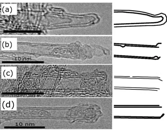
Fig. I.8: TEM images of carbon nanotubes opened by (a) boiling HNO3, (b) boiling acidified
KMnO4, (c) HF/BF3 at room temperature and (d) OsO4 solution at room temperature.
Schematic drawings are shown to help in visualizing the opened nanotubes [71].
Recently, it was discovered that hydrothermal treatment of MWNT for 6 h in autoclave (473K) in a presence of H2O2 (30%) can open the tips (Fig.I.9) [87].
Fig. I.9 : HRTEM images of (a) raw MWNT and then (b) MWNT opened by H2O2 in
autoclave [87].
a)
b)
“Piranha” solution is well known as a very aggressive oxidant and can be also applied to open the end of CNT. The 4:1 mixture of 96% H2SO4 and 30 % H2O2 results in the
formation of the strong oxidant H2SO5 (Caro’s acid).
H2SO4 + H2O2 → H2SO5 +H2O (eq. I.2)
Treatment with a mixture H2O2/H2SO4 was introduced by Smalley et al. [80] as a
method for chemical shortening of SWNT.
The same research group has shown that piranha solution heated up to 70°C successfully damages the sites in the nanotubes sidewalls and induces cutting and opening of SWNT [88, 89]. After a 9 h treatment at 70°C, the average length was less than half of the original length, but the weight loss was about 54 %.
It was also demonstrated that treatment of CNT by SF6/O2 minimises sidewall damage
by deactivating the metal catalyst during oxidation. This fluorination treatment is used as a first step of opening and cutting of CNT introducing carbon-carbon bonds breakage. Once the carbon-carbon bonds were damaged, etching by piranha solution for 9h at 70°C was applied and in this case 70-80% of the tubes were found with a final average length of 100 nm. Piranha solution is capable of attacking existing damaged sites and consuming the oxidised vacancies to generate cut SWNT (Fig.I.10) [89].
Fig. I.10 : Schematic for etching of SWNT. This etching can occur from (a) the ends of the nanotubes or (b) at a damage site where carbon-carbon bond breakage has occurred
I.3.2.2. Dry route
The dry route method for opening of CNT is fast, and scalable to large quantities. Gas phase thermal oxidation processes are often used as a part of CNT purification protocols. Ajayan et al. [90] first found that MWNT can be opened by oxidation in air. In this experiment, MWNT were heated only for 10 min at 800°C and as a result, about 20% of the tubes were completely open. Even for tubes which were not completely open, peeling of the outer layers occurred, initiating at the capped ends of the tubes. This peeling results in the thinning of the tubes layer by layer and seems to be just the reverse of the layer-by-layer growth mechanism. A few years later, opened MWNT have been investigated after thermal treatment in air [91]. It was shown that although the shortening of the tubes takes place at the ends of the tubes, the dominant burn-off mechanism makes the walls to be thinned. Tran et al. evidenced that the oxidation of MWNT in air is an efficient method to produce open nanotubes [92]. It was shown that after treatment of the tubes in air at 600°C for 5 min about 68 % of the tubes were opened. Moreover the average length of the tubes was shortened from over 5 µm to approximately 500 nm.
The theoretical calculations of Zhu et al. [93], concerning adsorption and desorption of an oxygen molecule on CNT, suggest that carbon nanotubes can survive selectively during the oxidative etching process with a precise control of the temperature. Fan et al. [94] experimentally demonstrated the importance of the temperature rate when the oxidation was performed in air. It was shown that a slow temperature-increase of 1°C/ min can improve the selectivity of the opening of SWNT and also give better quality of the final product. Subjecting raw SWNT obtained by arc process to a thermal treatment at 380°C in air within a tubular furnace is able to create openings in the sidewall as wide as 0.7 nm or more with an overall weight loss in the range of 40 % (including the impurities in the sample ) [58].
Single-Walled Carbon Nanohorns (SWNH) were also found to be attacked by CO2 at 1273 K
(Fig.I.11)[95].
Fig. I.11 : Schematic illustration of nanohorn oxidation during heat treatment in CO2 [95].
Gas or liquid phase oxidation procedures are efficient in opening MWNT or SWNT, although conditions have to be more severe for the former. The wet oxidation is carried out at temperatures below 150°C, whereas gaseous methods typically required temperature of at least 400°C. However, liquid phase oxidation tends to generate residues that may more or less cover the nanotubes, thereby hindering subsequent treatments (such as filling) or investigations (such as TEM). In this regard, gas phase oxidation may often be preferred.
I.3.3. Secondary reactions during opening
During the opening of CNT, due to the very strong oxidising conditions some secondary reactions like functionalisation can take place. Typically, when the tubes were opened by oxoacids such as HNO3 or mixture of HNO3/H2SO4 carboxylic functional groups
(-COOH groups) appeared on the surface of CNT. In the same time, the metal catalyst nanoparticles and the amorphous carbon present in the samples were also attacked by the acids. In most cases, these impurities were totally removed. When the tubes were opened by some other oxidants, functionalisation and purification of the samples were also observed. During opening of CNT in air, the more reactive amorphous carbon impurities and pentagonal
carbon shells around the catalyst nanoparticles were also burned, what leads to the purification of the samples.
I.3.3.1. Functionalisation by oxidising treatments
Most of the methods used for opening of CNT such as oxidation by oxoacids (HNO3 or H2SO4/HNO3) or by some other oxidants were often used also in order to modify
the CNT surface and to form functional groups.
Kuzmany et al. [96] showed that when SWNT were treated in reflux by 2M and 14M HNO3 for 11h carboxyl groups were formed on the walls (Fig.I.12). When reflux with conc.
HNO3 for 1.5 h was applied, SWNT were found to be covered by carboxylic functions as
shown by the presence of a broad infra-red peak at 1741 cm-1, which is assigned to –COOH groups [97]. The creation of carboxylic (–COOH) and sulfonic (SO3H) groups was also
observed when SWNT were treated by a mixture 1:1 of H2SO4 and HNO3 only for 3 min
using microwave treatment [98].
Musso et al. [99] investigated the functionalisation of MWNT by H2SO4/HNO3 (1:3)
for 5h at different temperatures (0°C, room temperature and 70°C). In the three cases the oxygen-containing functional groups interacted with the tubes surface creating –COOH and –SO3H groups.
The functionalisation by some other oxidants such as KMnO4, which is a well known
powerful oxidant used for opening of CNT, was also studied [100]. The oxidation process was performed by adding KMnO4 to a suspension of MWNT in H2SO4. Some functional groups,
particularly –COOH and –OH, were generated by this technique. Using the protocol proposed by Zhang et al. [100] it was found that, after treatment of DWNT with KMnO4 and H2SO4
and sonication for 8h, carboxylic groups were formed on the external wall of DWNT (which protect the internal one) [101].
Recently, it was reported about functionalisation of MWNT in K2Cr2O7/H2SO4
solution (stirring/reflux 2h) which is an effective treatment agent for introducing –OH groups for short treatment times [102]. H2O2 was also used to functionalize MWNT [103] and it was
observed that aldehydic and hydroxyl groups were dominating.
In order to estimate the amount of reactive groups on the CNT surface after chemical modification induced by the oxidation the samples usually were analysed by Fourier transformed Infrared spectroscopy (FT-IR) or X-ray photoelectron spectroscopy (XPS) [99] The estimation of the number of the functional groups can be determined by argentometric titration [104]. The electron scanning microscopy (SEM) and transmission electron microscopy (TEM) can be also used in order to study visually the structural changes after the oxidative treatments.
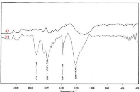
Using FT-IR spectroscopy, Wang et al. [98] determined the structure of the chemical functional groups formed after oxidation of SWNT by a mixture of H2SO4/HNO3 (1:1). The
line at 1719 cm-1 was assigned to the C=O stretching mode of the –COOH groups on the SWNT, whereas the intense, broad line centred at 3422 cm-1 was assigned to the –OH stretching mode of the –COOH groups. The strong line observed at 1355 cm-1 was assigned to the asymmetric SO2 stretching mode of the acid sulfonate (-SO2OH) group. The FTIR
spectrum is consistent with elemental analysis which showed that one over three of the carbon atoms on the SWNT backbone was carboxylated, and one over 10 was sulfonated.
Li et al. [105] found that, in MWNT treated by H2SO4/HNO3 mixture for 8h (60°C)
the total percentage of acidic sites calculated by acid-base titration was about 0.2-1%. Zhang
et al. [106] demonstrated that after oxidation of SWNT with the same acid mixture for 2h one
new peak around 1719 cm-1 appears. It is normally assigned to the C=O vibration in the COOH groups, which means that the acid-mixture treatment will introduce some C=O groups to the end or the side of the SWNT.
The XPS technique can be used to estimate the quantity of oxygenated functions at the surface of the tubes (semi-quantitative analysis). Using XPS, Musso et al. [99] found that the level of oxygen in MWNT samples after oxidation by H2SO4/HNO3 (1:3) for 5h goes from
8.7 wt.% from samples treated at 0°C to 20.5 wt.% at 70°C. XPS was also used to characterise MWNT oxidised by KMnO4 in H2SO4 and showed that about 12% of carbon atoms are
bonded with an –OH group and 7.45% with a –COOH group [100].
Acid-base titration of the opened nanotubes gives more precise estimation (depending on the purity of the sample) of the concentration of the surface acid groups [71]. The concentration of the surface acid groups on the nanotubes opened by the different oxidants was found to be in the range of 2 x 10²⁰-10 x 1020 acid sites/g of nanotubes, except in the case of OsO4 which gave a concentration of 5 x 10¹⁹ sites/g (Table I.1) [71].
Table I.1. Estimation of the concentration of the surface acid groups after acid-base titration [71]
One recent paper describes the problems of functionalisation of SWNT and MWNT by reflux in 9M HNO3 for 1-24 h [107]. The oxygen-containing groups found in the sample are
tubes (pentagonal carbon structure) and on defective parts of the walls but also on carbonaceous fragments (CFs) adsorbed on MWNT during the oxidation reaction. Actually, over-oxidation might cause CNT collapse and produce carbon species in the form of CFs; This process also produces so-called cutting of CNT. With a strong oxidant, carbon will be transformed to CO2. This process can be described by the following equation:
When the oxidised CNT were washed by NaOH solution, the carboxylated carbonaceous fragments were removed (Fig.I.13) and the quantity of functions (estimated from TEM, Raman scattering spectroscopy, thermogravimetric analysis and XPS) decreased [107].
Fig. I.13: The process of CNT oxidation [107].
The observation of these samples also suggests that carboxyl related secondary bonding forces might play a role in the stacking of oxidised SWNT and formation of bundles
The functionalisation of the tubes makes them useful in many applications. It was shown that the MWNT covered by carboxylic (-COOH) or carbonyl (-C=O) groups provide favourable nucleation sites for metal nanoparticles (Pd, Rh and Ru) growth [109] or to cover the nanotubes surface with Pt [110], RuO2 [111] or Ag [112] nanoparticles. In the last years,
the functionalised CNT took an important place in medicine. SWNT were functionalised by H2SO4/HNO3 (3:1) and the existence of –COOH groups provided precondition of covalent
immobilization of enzymes [113]. For bio-application of CNT, the functionalisation is required in order to solubilise CNT and to allow biocompatibility and low toxicity. When the tubes were functionalised, for example by HNO3, the –COOH groups can be used as active
site for conjugating with hydrophilic polymers suitable for imaging or drug delivery [114].
I.3.3.2. Purification of CNT
Most of the methods for opening of CNT are also used in order to purify them from amorphous carbon impurities or metal catalytic nanoparticles. In general the two methods which were used for opening (gas phase oxidation and liquid phase oxidation) are also often used in purification.
I.3.3.2.1. Gas phase oxidation
In gas phase oxidative purification, CNT are purified by oxidising carbonaceous impurities at a temperature ranging from 225°C to 760°C under an oxidising atmosphere [115]. The commonly used oxidants include air [116-119], CO2 [120] or steam [121].
High temperature oxidation in air is an extremely simple and successful strategy for purification of amorphous carbon impurities in CNT. If the temperature is high enough the carbon oxidises and forms carbon dioxide (Eq. I.3 and I.4):
C + O2 → CO2 (eq. I.3)
2 C + O2→2 CO (eq. I.4)
Ebbesen et al. [116, 119] first reported about opening and purification of MWNT by oxidising the as-prepared sample in air at 750°C for 30 min. However, due to the very strong oxidation, the yield of pure MWNT is very low (1-2 wt. %). Few years later, in order to remove carbon nanosphere impurities, Bandow et al. [122] decreased the oxidising temperature to 500°C for 30 min in dry air. By this treatment, the purify of MWNT reached 90%. Colomer et al. [123] found that the best conditions for purification of amorphous carbon impurities in a MWNT sample were at 500°C for 210 min where the yield of the purified tubes was 45 %. It has to be pointed that purification of CNT in air is usually followed by additional washing with for example NaOH or HCl [124].
High-yield purification of SWNT was investigated by Moon et al. [117]. It was concluded that amorphous carbon impurities were removed at 470°C for 50 min, evidenced by SEM images. Many authors mention that purification in air was found to be definitely successful in order to remove amorphous carbon impurities, while Gijewski et al. [125] inform about problems with purification of graphitic nanoparticles impurities in SWNT. Due to the higher oxidation stability than SWNT, some graphitic nanoparticles remained in the sample even after air oxidation at 355°C for 200 min.
Li et al. [126] observed that carbon nanoparticles were not removed at 400-650°C, while at 650-750°C they were oxidised together with DWNT. The problem of the quality of the purified DWNT after air purification was studied by Raman spectroscopy later [127]. The results show that at 440°C the D band which corresponds to the defect structure was completely eliminated but information about the yield was not given.
As a conclusion the gas phase oxidation is a simple method for removing carbonaceous impurities and opening the caps of CNT apparently without introducing sidewall defects,
although it cannot be used to directly get rid of metal catalyst and large graphite particles [115].
I.3.3.2.2. Liquid route oxidation
Liquid route oxidation used for opening of CNT was also used for their purification. The liquid route purification is supposed to oxidise the residual metal nanoparticles, amorphous carbon and graphitic nanoparticles from CNT samples. Purification with HNO3 is the most
popular acidic method for opening CNT but also for removing of catalyst metal nanoparticles. Using the procedure of Liu et al. [80], it was found that simple reflux of SWNT in 2.5M HNO3 for 24h can remove almost all metallic nanoparticles leaving sometimes empty
nanocapsules [128]. After electron microscopy investigations of SWNT treated for 45h in 2-3 M HNO3, it was found that Ni and Co nanoparticles were almost completely eliminated,
but carbon-coated SWNT in bundles were still observed [129].
Two years later, Hu et al. [130] reported a systematic evaluation of the use of HNO3 as a
purification treatment for SWNT. It was concluded that by increasing the concentration of HNO3 (3, 7 and 16 M) and the treatment time (6, 12 and 48h), the metal content decreases
(from 28.1 wt. % to 0.2 wt. %) (Fig.I.14). At the same time it was found that the weight loss increased while increasing the concentration of HNO3 and finally after the oxidation by 16M
![Fig. I.5: Specific surface area of carbon nanotubes versus their diameter and number of walls [22]](https://thumb-eu.123doks.com/thumbv2/123doknet/2231908.16050/24.892.278.617.476.778/specific-surface-carbon-nanotubes-versus-diameter-number-walls.webp)
![Fig. I.28 : HRTEM of MWNT one-step filled with FeBiO 3 crystallite [73].](https://thumb-eu.123doks.com/thumbv2/123doknet/2231908.16050/60.892.218.675.860.1104/fig-i-hrtem-mwnt-step-filled-febio-crystallite.webp)
![Fig. II.1 : Combustion methods for synthesis of Mg 0.9 Co 0.1 O powder [53].](https://thumb-eu.123doks.com/thumbv2/123doknet/2231908.16050/78.892.187.709.539.714/fig-ii-combustion-methods-synthesis-mg-o-powder.webp)