OATAO is an open access repository that collects the work of Toulouse
researchers and makes it freely available over the web where possible
Any correspondence concerning this service should be sent
to the repository administrator:
[email protected]
This is an author’s version published in:
http://oatao.univ-toulouse.fr/22928
To cite this version:
Kaiser, Thomas and Oztarlik, Gorkem and Selle, Laurent and
Poinsot, Thierry Impact of symmetry breaking on the Flame
Transfer Function of a laminar premixed flame. (2019)
Proceedings of the Combustion Institute, 37 (2). 1953-1960.
ISSN 1540-7489
Official URL:
https://doi.org/10.1016/j.proci.2018.06.047
Impact of symmetry breaking on the Flame Transfer
Function of a laminar premixed flame
T.L.
Kaiser
a,*,G. Ôztarlik
a,L.
Selle
a,b,T.
Poinsot
a,b • IMFT (Institut de Mécahique des Fluides de Toulouse), 2 Allée Camille Soula, 3/400 Toulouse, Frahceb CERFACS, 42 Avenue Gaspard Coriolis, 31057 Toulouse Cedex 1, France
Abstract
This work presents a numerical study of the acoustic response of a laminar flame with tunable asymmetry. A V-shaped prernixed flame is stabilised in the wake of a cylindrical flame holder that can be rotated. The configuration is symmetric when the flame holder is fixed but increasing its rotation rate breaks the symmetry of the flow. This configuration is submitted to acoustic forcing to measure the effect of rotation of the flame holder on the Flame Transfer Functions. lt appears that the asymmetry of the two flame branches changes their respective time delays, resulting in interference in the global unsteady heat release rate fluctuations. Consequently, the Flame Transfer Function exhibits dips and bumps, which are studied via larninar Direct Numerical Simulation. Potential applications for the control of combustion instabilities are discussed. Keywords: Laminar flame; Symmetry breaking; Interference; Laminar ONS; Rotating cylinder
1. Introduction
Combustion instabilities caused by a coupling of heat release fluctuations and acoustic modes of the combustion chamber are one of the key un certainties in the development process of gas tur bines. Their consequences may range from limiting the operating conditions to the destruction of the combustion chamber.
Combustion instabilities involve various com plex physical mechanisms. Therefore, canonical test cases are often used to isolate certain
phenom-* Corresponding author.
E-mail address: [email protected] (T.L. Kaiser).
ena. ln this context, several configurations involv ing laminar flames in various shapes have been studied in the past. Besides V-flames and conical flames [1,2], the case of a flame anchoring in the wake of a bluff body in laminar cross flow, has been studied using numerical and analytical ap proaches. Using larninar Direct Numerical Simu lations (ONS) validated by experiments, Brebion et al. [3] investigated the influence of the cylin drical flame holder's temperature on the flame an choring mechanism. ln their follow up study, Mejia et al. [4] investigated the influence of the cylin der's temperature on the Flame Transfer Function (FTF). The effect of rotation of the cylinder on the flame anchoring mechanism was explained by Xavier et al. [5] and Mejia et al. [6]. Their results
Upper flamc branch X'ref X
Lower flame branch
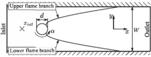
Fig. 1. Transverse eut of the computationaJ domain. showed that rotating the cylinder breaks the sym metry of both flame branches. Since the asymme try of both flame branches is tunable by the ro tation rate, it is a variable parameter to adapt the flame topology, without changing the flow velocity or the cold gas mixture. The dynamic response of both flame branches and their interaction neverthe Jess remain unknown.
This article focuses on influence of the cylinder rotation rate on the dynamic response of the flames to harmonie acoustic forcing. ln Section 2 the setup and numerical strategy are laid out. Section 3.1 de scribes the influence of the rotation rate on the un perturbed flame topology and Section 3.2 discusses the FTF of the case without cylinder rotation. This FTF is compared in Section 3.3 to FTFs for vari ous cylinder rotation rates. Section 3.4 discusses the flame branches topology in case of monochromatic forcing for several rotation rates. Finally, the results are concluded and discussed in Section 4.
2. Configuration and simulation framework The configuration corresponds to that of Xavier et al. [5, 7): it consists of a constant-section rect angular channel (width W
=
34 mm and depth 94 mm) at the center of which a stainless-steel cylin der (diameter d=
8 mm) serves as a flame holder (see Fig. 1). The cylinder is mounted on an elec tric motor with a controlled rotation speed ranging from 600 to 20,000 rpm. The normalised rotation rate is defined aswd
a=-2ub (1)
where Ub is the bulk velocity of the premixed gases in the channel.
As shown in previous studies on this exper iment [3,5, 7), because of its geometry and the Jaminar conditions, two-dimensional simulations are adequate. Laminar ONS are performed using the AVBP code [8], jointly developed by CERFACS and IFP Energies nouvelles, which solves the com pressible Navier-Stokes equations for multicom ponent reacting flows on unstructured grids. The numerical integration is performed by a two-step Taylor -Galerkin scheme called TTGC [9], which is of third-order in both space and time. ln the current work, the combustion of methane and air is modelled via an analytically reduced skeletal
mechanism accounting for 19 transported species and 11 quasi-steady species [10). This mechanism, referred to as LUJ9, is based on the GRJ-mech3.0 mechanism [11) and reproduces the adiabatic tem perature and flame speed over a wide range of operating conditions. It also includes Jow temperature-chemistry, required to describe flame wall interaction at the flame holder interface.
The Jateral walls are water-cooled and mod elled by a no-slip iso-thermal boundary condi tion (Twau
=
292K). The computational domain extends from x = -35 mm to x = 97 mm, where x=
0 corresponds to the center of the cylinder. The inlet and outlet boundary conditions are mod elled via the Navier-Stokes characteristic bound ary conditions (NSCBC) [12). The inlet is fed by a methane-air mixture at equivalence ratio <l>=
O. 75 and temperature T.=
292 K. The velocity profile is given by experimental measurements. The bulk speed is ub=
0.8 mis. A pressure of p=
100, 700 Pa is imposed at the outlet. This operating point is far away from flame detachment of the cylinder.The boundary condition at the cylinder's sur face is a no-slip rotating wall, which was shown by Mejia et al. [7] to accurately account for the rota tion of the flame holder. An estimation of the Biot number of the present cylinder is 0.01, meaning that the assumption of spatially uniform temper ature is valid. Consequently, the cylinder tempera ture, Tcy1, can be obtained by solving [5):
dTcy1
s
.
dt=
CppV(Qcond - Qrad), (2) where t denotes time, S the cylinder surface, p and V the density and the volume of the cylinder, and Cp the mass specific heat capacity. Qeond and Qrad are the conductive and radiative heat fluxes, respectively. Qcond is obtained by integrating the laminar ONS heat flux long the cylinder surface. Radiation is governed by the Stefan-Boltzmann radiation law [13):• ( 4 4 )
Qrad
=
E<l T,,yl -Twall • (3) where <1 is the Stefan-Boltzmann constant, and the emissiency coefficient, E, is set to 0.9. The gas is assumed to be fully transparent and the tempera ture of the surroundings of the cylinder is supposed to be equal to the temperature of the cooled walls Twall=
292 K. Since the time scales of the chemical reactions and that of the preheating of the cylinder are distinctively different, the transient heat up of the experiment can be accelerated following, for ex ample the strategy presented in [14). Also, because of the Jow Biot number and the high rotation rate, once in the permanent regime, the temperature of the cylinder is homogeneous and constant.Finally, regarding spatial resolution, the coars est cell size in the domain is l:ix
=
500 µ,m, while it is l:ix=
70 µ,m close to the flame, which corre sponds to 8 points in the flame [15). Based on a(a) a=0 (c)a= 1.25 ulm/•] 7.1 :; 1.7 :8
...
2.3 Il-0.tJ
(b)a=0.625 (d)a=2.5 u(m/sl 6.6:,: "' 34;; .... 0.2 Il .30J ulm/•l 7.0:,: "' 5.0§
2.s 11 .o.sJ ulm/sl [7·0�
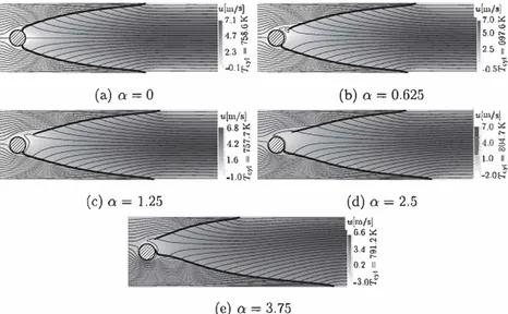
�40 � 1.0 Il -2.oJ (e)a=3.75Fig. 2. Field of velocity component in main flow direction, u, with stream lines highlighted as thin black solid lines, iso
surface of heat release as thick solid line and cylinder temperature for various cylinder rotation rates, a.
mesh convergence study focusing on one dimen sional flame head on quenching, the cell size at all solid walls is set to lix
=
25 µm. The setup of the mesh convergence study is presented in [16].This numerical strategy was successfully com pared to experimental results in many previous studies [3,5, 7], including investigations on flame wall interaction [16] and it is used here without modification.
3. Results
In this section, the influence of rotation of the flame holder on the response of the flame to acous tic waves is studied. This analysis is conducted in the framework of FTF, i.e., in the linear regime cor responding to low amplitude perturbations.
3.1. Steady-state ana/ysis
First, the steady flame shapes are presented in
Fig. 2, for all of which the fluctuations in heat re lease are smaller than 0.05% of the mean heat re lease value. As expected, without rotation the flame
is symmetric (Fig. 2a) but this symmetry is broken
by the rotation of the flame holder. With increas
ing rotation rates, the root of the upper branch de taches from the cylinder, but moves upstream again
for very large values of et (cf. Fig. 2e). The tip of
the upper branch moves downstream until et
=
l .25but then goes back upstream, even past its loca tion for the symmetric flame. Regarding the lower branch, it always remains attached to the cylinder and its tip is monotonously pushed downstream. A thorough investigation of the effect of bluff body
rotation on the flame root is provided by Xavier et al. [5].
From the simple observation of the flame shape in the steady state, one can anticipate that the two branches will have a very different response to acoustic waves. lndeed, one can show from first principles [17,18] that the flame response is driven by its length and the dynamics of its root. While the length greatly impacts the delay, the dynamics of the flame root drives the gain of the FTF [4,6]. Moreover, the rotation of the cylinder breaks the symmetry of the flow so that the bulk velocities on both sides of the flame holder are different. This will change the speed at which perturbations travel on the flame front, also impacting the flame de lay. Finally, because of the complex flow pattern around the cylinder, the temperature of the flame holder changes with the rotation rate (see right side of Fig. 2). lt first decreases significantly at low ro tation rates and increases again, past the reference value without rotation. The quantitative measure ment of these changes is reported in Table 1, which gives the cylinder temperature, the flame root and tip positions and the bulk velocities for the two branches for various rotation rates.
Ali these changes in the flame front topology and the flow field point towards a modification of the FTF, which will be studied in the next sections.
3.2. Flarne response without rotation
This section focuses on the FTF of the var ious flames, starting with the case without rota tion. Under the assumption that the system is linear and invariant, it has been shown in many studies that the Wiener-Hopf Inversion (WHI) is a
pow-Table 1
Properties taken from the laminar ONS solution for different rotation rates, a.
a Tcyl (K) Xroot,y- Xroot,y+
(mm) (mm) 0 758.6 1.9 1.9 0.625 697.6 2.4 7.8 1.25 757.7 2.4 12.1 2.5 804.7 3.4 14.8 3.75 791.2 4.3 8.3
1Jl�I
-30"-- -�--�-�---'---'-o 50 100 150 200 250 JIHzlFig. 3. FTF without rotation (a = 0) based on WHI and monochromatic forcing.
Fig. 4. Flame shapes behind a non-rotating cylinder; dashed line: unperturbed flame; solid line: flame forced at 80 Hz; Insert: definition of flame angle, a, and flame normal displacement, �.
erful methodology for the determination of FTFs
[19-21). ln this method, the transfer fonction of a
system is estimated by broad band forcing of the system and subsequent correlation analysis of its input and output signal. A detailed description of the method is provided in [22,23). ln order to re main in the linear regime, the forcing amplitude for the estimation of the FTF is kept at 1 % of the bulk velocity. The reference point for the velocity per turbations is at x
= -
JO mm and y=
O. Figure 3shows the FTF of the symmetric reference flame (i.e., o:
=
0), obtained by a WHI analysis of Jaminar ONS data. As seen in previous studies of this con figuration, this flame only responds under 250 Hz and shows a strong gain ( > 2) at Jow frequencies, here around 80 Hz. The phase of the FTF is linear, corresponding to a constant lime delay r defined as the slope of the phase. For the present operat ing point, r=
35.5 ms. The accuracy of the WHI was tested by perfonning FTF evaluation at vari ous discrete frequencies (see circles in Fig. 3).We now investigate the motion of the flame front under harmonie forcing at 80 Hz, i.e., close to the frequency of the peak in the FTF. Figure 4 presents the mean and perturbed flame front and
Xtip,y-(mm) 60.1 63.4 65.2 74.8 90.1 Xtip,y+
(mm) v,-(mis) (mis) Vy+
60.1 1.05 1.05 67.3 1.08 1.02 68.2 1.12 0.97 62.2 1.26 0.83 44.5 1.46 0.64 - 2 1T S 1 3�, --·-· 'P = -cp=O e - .. , 2
.;_;.?
V >I<
-cp=3,r 0 20 40 60 80 -·-·cp=2 llmmlFig. 5. Flame displacement, �, along the flame front with out rotation for various phases at f = 80 Hz. Forcing am plitude: 5%ub, 6 -� 4 02 - 0 � 1-0'. =0 ··•· 0'.=1.25 -0-·0'.=3.751 _ -0-· ü
=
0.625 -ü=
2.5 _ -·-'-.
·-
..._
'·-·-...!
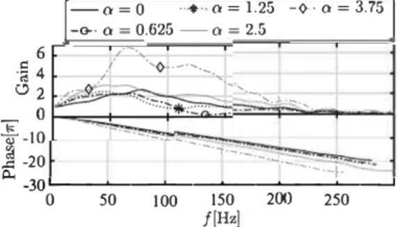
-JO ..<:: -20 -·-·--·-·-·· A. -30,..._ _ ___. __ ..._ __ ..._ __ .._ _ ___. __ _. 0 50 100 150 200 /[Hz] 250 Fig. 6. Influence of flame holder rotation on the FTF. shows the definition of the normal displacement 5 between the two. ln order to elucid.ate the dynam ics of the flame, the evolution of 5 along the flame front is presented in Fig. 5 at four ditferent phases of the harmonie excitation. lt appears that the am plitude of the displacement increases weakly along the flame front but shows non-Jinear deformation close to the flame tip. lt is also qui te clear that a lot of the variation in the flame surface is caused by the flame-wall interaction at the flame tip.3.3. Flarne response with rotation
Figure 6 shows the FTFs for various rotation rates, up to o:
=
3.75, including the case without rotation as the reference. The first observation is that the maximum gain is marginally atfected up to o:=
2.5. However, between o:=
2.5 and o:=
3.75, it increases by at Jeast a factor of 2. The location of the maximum gain remains in the Jow-frequency range (between 50 Hz and 80 Hz), but without clear trend.The second observation is that for many rota tion rates, the gains exhibit strong dips (see markers
-a,= 0 ... a,= 1.25 -·-·a,= 3.75 -·-·a,= 0.625 -a,= 2.5 o Monocbr.
50 100 150 200 250
/(Hz)
(a) Upper flame branch (y+).
·� 4 '·-...�
��
!:;;;;::;:
:=�
-
·�
--�
·
�
·
�
,
·
�
:�
�
,
:���
,
�
�
'·
�
-·�
�
c·,
�=�
: -10j
-20... _
--30�-�--�-�--�-�-� 0 50 100 150 200 250 /(Hz)(b) Lower flame branch
(y-).
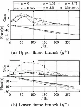
Fig. 7. FTF of individuaJ ftame branches versus rotation rate a; the circles mark results of monochromatic forcing ata = 3.75.
in Fig. 6). It is anticipated that these dips could stem from the symmetry breaking of the flame, result ing in interference between the responses of the two flame branches. Regarding the phase of the FTF, it is linear in ail cases and the corresponding delay monotonously increases with the rotation rate.
ln order to investigate the dips in the FTF gain, the two flame branches are now analysed sepa rately. The underlying assumption is that their dy namics are not, or sufficiently weakly coupled.
The FTF of the upper (y> 0, Jabelled y+), re
spectively Jower (y< 0, labelled y-) branches are determined by integration of the heat release rate over one half of the domain. The reference point for the velocity is the same as for the global FTF and the heat release rate fluctuations are nor malised by the total flame power. The resulting FTFs are displayed in Fig. 7a for the y+-branch and
in Fig. 7b for the y--branch.
For the upper branch, the variations in max imum gain are limited but the cutoff frequency clearly decreases with a. lt goes from 250 Hz with out rotation down to around 130 Hz for a> 2.5. The delay of the flame response first increases and then decreases with a maximum around a = 1.25, which is consistent with the evolution of the steady upper-flame length shown in Fig. 2.
The evolution of the FTF of the Jower branch is very different. First there is no decrease in the cutoff frequency but the striking feature is that the maximum gain increases drastically past a = 2.5
over a broad frequency range. The delay of the FTF monotonously increases with a, replicating the in crease in flame Jength concomitant with the bulk velocity increase for y< O. Despite the high gains at a = 3.75, results of monochromatic forcing, which are illustrated by the circles in Fig. 7, and WHI are in good agreement.
We now investigate the hypothesis that the breaking of the flame symmetry results in an inter ference between the two branches. A practical ap plication for this modification of the FTF via ro tation of the flame holder could be the control of combustion instabilities by tuning the location of the dips in the FTF. A simple mode) can be built to predict the frequency at which this dip occurs. lt is based on the idea that the dip is the conse quence of the interference between the responses in heat release fluctuation of the two branches. The total heat release fluctuation is equal to the sum of the heat release fluctuation of both branches, q;0I =
<f,,+ +
<1,,-.
lntroducing the FTF using the notation of Crocco, the fluctuation in heat release can be re lated to a harmonie velocity fluctuation, ri, which yields:q'�I = �(n
y+
+
n,-exp (iwM)) exp (iwry+ ). (4)q u
Here, n are the gains of the respective branches
and the difference in time delays is depicted as
Lh = r,--ry+. From Eq. (4) it is evident, that the
gain of the global FTF is depending on the phase angle between the two branches, given by
l:i</J = wl:J.r. (5)
The two extreme cases are ideal constructive in terference and ideal destructive interference. For the former case, the phase angle between the both branches' heat release signais is O or an even mul tiple of ,r. Theo the gain of the global heat release reduces to n,o, = ny+
+
ny-. ln the other case, the difference in phase angles is an odd multiple of ,r, so that the gain of the global heat release is equal to n101 = ln1+ -ny-1 · Therefore, the frequency at which destructive interference is maximal can be deduced from Eq. (5):l:i</J /d,,,=
2,rt:J.r' l:i</J=(2n-l),r, nEZ. (6) The values, extracted from the laminar DNS, of the delays of the two branches (ry+ and r1-for the upper and lower branch, respectively), their differ ence, l:J. r, and the first two frequencies of construc tive and destructive interference lfc,n and /d,n for
n = 1 and n = 2) are given in Table 2. For a = 0.625 and a = 1.25, the predicted values of
/d,
1 corre spond very well to the FTF of Fig. 6. For a = 2.5, the first destructive interference occurs at a fre quency where the gain of the upper-branch FTF is close to zero (cf. Fig. 7a). Consequently, the inter ference is not meaningful and no dip is observed in the FTF. Finally for the higher rotation rate (a =Table 2
Time delays of the two flame branches ( r,.+ and •y- for the upper and lower branch, respe<> tively) and vaJues of the first two frequencies for destructive and constructive interferenœ (cf. Eq. (6)). a •y+ (ms) •y-(ms) 6.r (ms) 0.0 35.5 35.5 0 0.625 40.9 37.1 -3.8 1.25 42.5 37.9 -4.6 2.5 38.6 41.6 3.0 3.75 33.6 49.7 16.1
3.75), the value of /d, 1 is again very low and a dip
is observed.
The frequency of the second dip,/d, 2, (Table 2) is much higher than the cutoff frequency of the flame response for all rotation rates except for a
=
3.75, which exhibits a dip around the expected value of 93 Hz. The frequencies /d, n are illustratedby the markers in Fig. 6, showing very good agree
ment with the location of the dips in the corre sponding gains. lt seems that the simple mode! of
Eq. (6) gives an accurate prediction of this phe nomenon, giving a posteriori confirmation of the hypothesis that there is indeed interference between the two flame branches.
Given the strong impact of symmetry breaking on the shape of the FTF, one may use the rotation rate of the flame holder to control combustion in stabilities. However, it can be anticipated that only the low rotation rates, say a < 1.25 can be of prac tical use for the present flame, first because of the strong decrease of the cutoff frequency of one of the branches, but also because of the large increase in gain of the other branch, which drives the gain of the total FTF and hinders the destructive inter ference.
3.4. Flame front dynamics
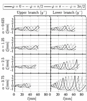
We pursue the analysis of the flame response by plotting the flame displacement along the flame front for the two branches in Fig. 8. As for the non rotating case, the frequency of interest is 80 Hz, which lies close to the peak in the gain of the FTF for all rotation rates.
We start the analysis for the upper flame branch.
For ail rotation rates a growth of the flame displace ment along the flame front is observed. With in creasing rotation rate from a = 0 to a = 2.5, the flame displacement amplitude at the flame tip de creases moderately. It appears that the response in flame displacement amplitude increases again be yond this rotation rate. The same trend can be ob served regarding the non-linear deformation close to the flame tip. This effect seems to decrease un til a rotation rate of a
=
2.5 and increase again for higher rotation rates. Nevertheless, only a small variation of the flame displacement amplitude at the flame tip is observed. At the Jower flame branch,fd,1 (Hz) fd,2 (Hz) /c,1 (Hz) /c,2 (Hz) 132 109 167 31 395 326 500 93 263 217 333 62 395 435 667 124
1
-
ip
=o---·l{)
= 1r12-ip = 7r -·-·<{> = 31r121 0Upper branch (y 1 ) Lower branch (y )
20 40 60 80 0
l[mm] 20 40 60 80 l[mm]
Fig. 8. Flame displacement, �, along the flame front at a velocity forcing of amplitude of 5%ub and/= 80 Hz for various phase angles, <p, and rotation rates a.
the amplitude of the flame root displacement at / = 0 seems to decrease with increasing rotation rate. ln contrast, the displacement growth along the flame front significantly increases, especially for rotation rates of a� 2.5. This goes along with a consider able increase in non-linearity, as can be seen in the right half of Fig. 8. Note that the flame displace ment monotonically grows along the flame front for both the upper and lower branch and all rotation rates until the flame tip, except for the Jower branch at a= 3.75. Here a saturation seems to occur and the fluctuation amplitude, while initially growing at the highest rate for Jow flame locations, stays ap proximately constant for/> 40 mm until the flame tip at /
= 87.4 mm. Figure 8 suggests, that the Jower
branch's drastic increase in gain of the FTF for rotation rates a � 2.5 might be due to some kind of convective instability mechanism which leads to a significant increase in flame displacement. The growth of perturbations artificially introduced into--Upper branch, (y+) -·-· Lower branch, (y-) -2
Îo
<l -2·---·-·
0 0.5 .-·-1 <,0[1r) 1.5Fig. 9. Relative ftame tip position with respect to the ftame tip position of the steady ftame, tn = X1;p -xti ,s, as a fonction of the phase angle of the velocity perturba tion, <p, for a cylinder rotation rate of a = 0.625; pulsa tion amplitude: 2% of bulk velocity; pulsation frequency:
132Hz.
a laminar flame has been observed before (e.g., by Petersen [24) and Mejia et al. [4D.
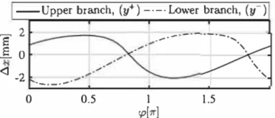
Finally, the flame tip movement is analysed. Figure 9 shows the flame tip position of the per turbed upper and lower flame branches with re spect to their positions in the unperturbed case for a cylinder rotation rate of a
=
0.625. The pul sation amplitude is at 2% of the bulk speed and its frequency is 132 Hz, i.e., at the frequency of ideal destructive interference. It appears that the tip movements are perfectly out of phase, which is expected since at these frequencies the FTFs show a phase difference of ,r and most of the heat re lease fluctuation is produced at the interaction of the flame tip and the lateral walls. Together withFig. 6, Fig. 9 shows that introducing rotation of a flame holder can be used to build a flame which be cornes almost insensitive to acoustic perturbation, suggesting that this could be used for combustion instability control. Note however that this result is obtained only in a limited frequency range.
4. Conclusion
The FTF of a laminar flame stabilised behind a rotating cylindrical bluff body is investigated for various rotation rates of the cylinder by the means of laminar DNS. The rotation causes a symmetry break between the two flame branches, where es pecially the flame tip positions vary significantly, especially for high rotation rates. FTFs are esti mated for each branch separately, assuming that they can be described as two independent Linear Time Invariant (LTI)-systems. The results show a difference in time delays between the upper and the lower flame branch. This is mainly due to an in dependent modification of the flame tip positions of both branches, caused by two effects: a detach ment of the upper branch from the cylinder and a modification of the bulk speeds in the two half domains due to the cylinder's viscous boundary layer. The resulting difference in time delay causes interference of the flames' heat release signais. At
frequencies where destructive interference is max imal, the global FTFs, which include both flame branches, as a consequence show deep gaps in the gain. The difference in time delay and therefore the frequency at which destructive interference of both flame branches occurs can be tuned by adapting the rotation rate of the cylinder. ln this context, the analysis suggests, that the rotation rate is a sui table and easily adaptable measure of open loop con trot of combustion instabilities. It is shown that for cylinder rotation rates, a � 2.5, the flame displace ment considerably grows along the flame front of the lower flame branch, leading to gains, that by far exceed the gain of the non-rotating configuration. This effect therefore limits the applicability of the method to moderate rotation rates and frequencies /� I 00 Hz. Most practical flames are highly turbu
lent, and the existence of a corresponding effect in the turbulent regime remains unknown. Neverthe less, the present paper underlines the asset of de creasing the gain of the FTF significantly around a specific frequency by being able to tune the asym metry of a combustion system which leads to de structive interference.
Acknowledgments
The research leading to these results has re ceived funding from the European Research Coun cil under the European Union's Seventh Frame work Programme (FP/2007-2013)/ERC Grant Agreement ERC-AdG 319067-INTECOCIS.
This work was granted access to the high performance computing resources of CINES un der the allocation A0032B07036 made by Grand Equipement National de Calcul Intensif.
References
(1) R. Blumenthal, P. Subramanian, R. Sujith, W Po lifke, Combust. Flame 160(2013) 1215-1224. (2)T. Schuller, D. Durox, S. Cande), Combust. Flame
134 {2003) 21-34.
(3) M. Miguel-Brebion, D. Mejia, P. Xavier, et al., Com bust. Flame 172 {2016) 15�161.
(4) D. Mejia, M. Miguel-Brebion, A. Ghani, et al., Com
bust. Flame 188 {2018) 5-12.
(5) P. Xavier, A. Ghani, D. Mejia, et al., J. Fluid Mech.
813 {2017) 127-151.
[6] D. Mejia, L. Selle, R. Bazile, T. Poinsot, !'roc. Com bust. /nst. 35 {2015) 3201-3208.
[7] D. Mejia, M. Bauerheim, P. Xavier, B. Ferret, L. Selle, T. Poinsot, /'roc. Combust. /nst. 36 {2017) 1447-1455.
(8) T. Poinsot, The AVBP Handbook, CERFACS, Toulouse, 2005.
(9) O. Colin, M. Rudgyard, J. Comput. l'hys. 162 {2000) 338-371.
(10)T. Lu, C.K. Law, Combust. Flame 154 {2008) 761-774.
[11] P.S.Gregory,D.M. Golden,M. Frenklach,etal., GRI-Mech, 2000. http://www.me.berkeley.edu/gri_ mech/(Accessed:23June2018).
[12] T. Poinsot, S. Lele, J. Comput. Phys. 101 (1992) 104–129.
[13] L.Boltzmann,Ann. Phys. 258(1884)291–294.
[14] F.Duchaine, A. Corpron, L. Pons, V. Moureau, F. Nicoud,T. Poinsot, Int. J. Heat Fluid Flow 30 (2009)1129–1141.
[15] M.Brebion,Joint Numerical and Experimental Study of Thermo-acoustic Instabilities , Institut de Mé-caniquedesFluidesdeToulouse,2016Ph.D.thesis.
[16] A.Ghani,T.Poinsot,Flow Turbl. Combust. 99(2017) 173–184.
[17] L. Boyer, J. Quinard, Combust. Flame 82 (1990) 51–65.
[18] A.Cuquel,D.Durox,T.Schuller, C. R. Méc. 341 (2013)171–180.
[19] A. Giauque, T. Poinsot, F. Nicoud, 14th AIAA/CEAS Aeroacoustics Conference, Van-couver,BritishColumbia,Canada(2007)2943. [20] A.Gentemann,C.Hirsch,K.Kunze,F.
Kiesewet-ter,T.Sattelmayer,W.Polifke,ProceedingsofASME TurboExpo,Vienna,Austria(2004)501–510. [21]W.Polifke,A.Poncet,C.Paschereit,K.Döbbeling,
J. Sound Vib. 245(2001)483–510.
[22]L.Ljung(Ed.),System Identification (2nd ed.): The- ory for the User ,PrenticeHallPTR,UpperSaddle River,NJ,USA,1999.
[23]A.Huber,W.Polifke,Int. J. Spray Combust. Dyn. 1 (2009)199–228.
[24]R.E.Petersen,H.W.Emmons, Phys. Fluids 4(1961) 456–464.