HAL Id: hal-01757797
https://hal.archives-ouvertes.fr/hal-01757797
Submitted on 4 Apr 2018
HAL is a multi-disciplinary open access
archive for the deposit and dissemination of
sci-entific research documents, whether they are
pub-lished or not. The documents may come from
teaching and research institutions in France or
abroad, or from public or private research centers.
L’archive ouverte pluridisciplinaire HAL, est
destinée au dépôt et à la diffusion de documents
scientifiques de niveau recherche, publiés ou non,
émanant des établissements d’enseignement et de
recherche français ou étrangers, des laboratoires
publics ou privés.
A Reconfigurable Compliant Four-Bar Mechanism with
Multiple Operation Modes
Abhilash Nayak, Haiyang Li, Guangbo Hao, Stéphane Caro
To cite this version:
Abhilash Nayak, Haiyang Li, Guangbo Hao, Stéphane Caro. A Reconfigurable Compliant Four-Bar
Mechanism with Multiple Operation Modes. ASME 2017 International Design Engineering Technical
Conferences & Computers and Information in Engineering Conference (IDETC/CIE 2017), Aug 2017,
Cleveland, United States. �10.1115/DETC2017-67441�. �hal-01757797�
A RECONFIGURABLE COMPLIANT FOUR-BAR MECHANISM WITH MULTIPLE
OPERATION MODES
Abhilash Nayak
´
Ecole Centrale de Nantes
Laboratoire des Sciences du Num ´erique de Nantes (LS2N)∗ UMR CNRS 6004
1 rue de la No ¨e 44321 Nantes, France. Email: Abhilash.Nayak@ls2n.fr
Haiyang Li
School of Engineering-Electrical and Electronic Engineering University College Cork, Cork, Ireland
E-mail: Haiyang.Li@umail.ucc.ie
Guangbo Hao† School of Engineering-Electrical and Electronic Engineering University College Cork, Cork, Ireland
E-mail: G.Hao@ucc.ie
St ´ephane Caro
CNRS, Laboratoire des Sciences du Num ´erique de Nantes (LS2N), UMR CNRS 6004
1 rue de la No ¨e, 44321 Nantess, France. Email: Stephane.Caro@ls2n.fr
ABSTRACT
Although reconfigurable rigid-body mechanisms have been extensively studied over two decades, their compliant counter-parts have not received the similar attention yet. This paper aims to design a reconfigurable compliant four-bar mechanism with multiple operation modes. A planar equilateral four-bar mech-anism is considered at its constraint singularity. The multiple operation modes of this linkage are kinematically exploited to de-sign a reconfigurable compliant four-bar mechanism, which gen-erates rotational or translational motions based on two actuated joints. Simulation is conducted to investigate the comprehensive kinematics of the reconfigurable compliant mechanism. A 3D printed prototype of the novel reconfigurable compliant mecha-nism at hand is presented.
INTRODUCTION
Although mechanisms are often composed of rigid bodies connected by joints, compliant mechanisms include flexible
el-∗IRCCyN (Research Institute in Communications and Cybernetics of Nantes)
merged with LINA (Computer Science Laboratory of Nantes) to give birth to LS2N (Digital Science Laboratory of Nantes) on January 1st, 2017
ements whose elastic deformation is utilized in order to trans-mit a force and/or motion. There are different ways to design compliant mechanisms, such as the kinematic based approaches, the building blocks approaches, and the structural optimization-based approaches [1–4]. In the kinematic optimization-based approach, the joints of a chosen rigid-body mechanism are replaced by ap-propriate compliant joints followed by pseudo-rigid body mod-eling [2–4]. This method is advantageous due to the extensive choice of existing rigid-body mechanisms and their modeling tools. Parallel or closed-loop rigid-body architectures gain an upper hand here as their intrinsic properties favour the charac-teristics of compliant mechanisms like compactness, symmetry to reduce parasitic motions, low stiffness along the desired de-grees of freedom (DOF) and high stiffness in other directions. Moreover, compliant mechanisms usually work around a given position for small range of motions and hence they can be de-signed by considering existing parallel manipulators in paral-lel singular configurations. Paralparal-lel singularity can be an ac-tuation singularity, constraint singularity or a compound sin-gularity as explained in [5–7]. Rubbert et al. used an ac-tuation singularity to type-synthesize a compliant medical de-vice [8, 9]. Another interesting kind of parallel singularity for a parallel manipulator that does not depend on the choice of
ac-l
A
D
B
C
y
0x
0y
1x
1Ʃ
1O
1(a,b)
O
0(0,0)
x
Ʃ
l
Ʃ
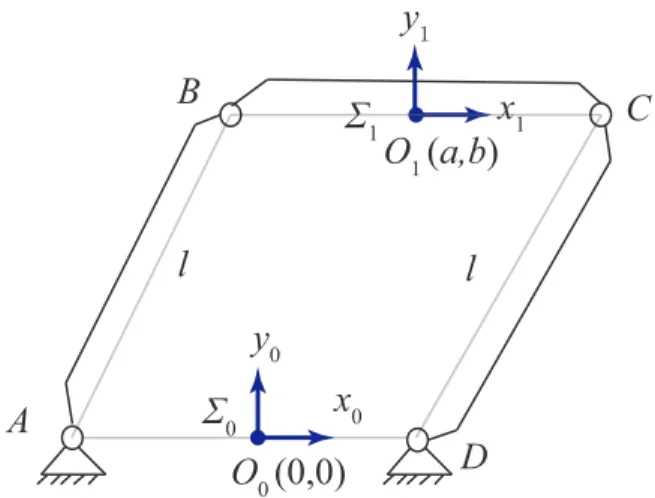
0FIGURE 1: AN EQUILATERAL FOUR BAR LINKAGE.
tuation is a constraint singularity [10]. It divides the workspace of a parallel manipulator into different operation modes result-ing in a reconfigurable mechanism. Algebraic geometry tools have proved to be efficient in performing global analysis of par-allel manipulators and recognizing their operation modes lead-ing to mobility-reconfiguration [11–13]. Though there are abun-dant reconfigurable rigid-body mechanisms in the literature, the study of reconfigurable compliant mechanisms is limited. Hao studied the mobility and structure reconfiguration of compliant mechanisms [14] while Hao and Li introduced a position-space-based structure reconfiguration (PSR) approach to the reconfigu-ration of compliant mechanisms and to minimize parasitic mo-tions [15, 16]. In this paper, one of the simplest yet ubiqui-tous parallel mechanisms, a planar equilateral four-bar linkage is considered at a constraint singularity configuration to synthe-size a reconfigurable compliant four-bar mechanism. From our best understanding, this is the first piece of work that considers a constraint singularity to design a reconfigurable compliant mech-anism with multiple operation modes, also called motion modes. This paper is organized as follows : Kinematic analysis of a rigid four-bar mechanism is performed to determine the constraint sin-gularities and different operation modes. Rigid-body replace-ment design approach is followed to further synthesize a recon-figurable compliant four-bar mechanism and the motion type as-sociated to each operation mode is verified through non-linear Finite Element Analysis (FEA).
KINEMATIC ANALYSIS AND OPERATION MODES OF A FOUR BAR LINKAGE
A planar equilateral four-bar linkage with equal link lengths, l is depicted in Fig. 1. Link AD is fixed, AB and CD are the cranks and BC is the coupler. Origin of the fixed frame (Σ0), O0
coincides with the center of link AD while that of the moving frame (Σ1) O1with the center of BC. The coordinate axes are oriented in such a way that the position vectors of the intersection points between the revolute joint axes and the x0y0plane can be homogeneously written as follows:
r0A= [1, −l 2 , 0] T r0 D= [1, l 2, 0] T (1) r1B= [1, −l 2 , 0] T r1 C= [1, l 2, 0] T (2)
The displacement of the coupler with respect to the fixed frame can be rendered by (a, b, φ ), where a and b represent the posi-tional displacement of the coupler (nothing but the coordinates of point O1in Σ0) and φ is the angular displacement about z0-axis (angle between x0and x1). Thus, the corresponding set of dis-placements can be mapped onto a three-dimensional projective space, P3with homogeneous coordinates xi(i = 1, 2, 3, 4) [17]. This mapping (also known as Blashke mapping in the literature) is defined by the following matrix M :
M = 1 0 0 2x1x3+ 2x2x4 x23+ x24 −x2 3+ x24 x23+ x24 −2x3x4 x23+ x24 −2x1x4+ 2x2x3 x23+ x2 4 2x3x4 x23+ x2 4 −x2 3+ x24 x23+ x2 4 (3)
The planar kinematic mapping can also be derived as a spe-cial case of Study’s kinematic mapping by equating some of the Study parameters to zero [11]. To avoid the rotational part of M to be undefined, the following equation is defined:
H:= x23+ x24= 1 (4)
Without loss of generality, xi can be expressed in terms of (a, b, φ ), as follows [17] :
x1: x2: x3: x4= (au − bv) : (av + bu) : 2u : 2v with u= sin(φ 2), v= cos( φ 2) (5) Constraint Equations
Points B and C are constrained to move along circles of cen-ters A and D, respectively and with radius l each. The position vectors of points B and C are expressed algebraically in frame Σ0 as follows :
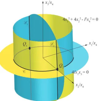
4x1 2 + 4x 2 2 - l2x 4 2 = 0 4lx1x3 = 0 Q1 Q2 x3/x4 x1/x4 x2/x4 L 1 L 2 C
FIGURE 2: CONSTRAINT MANIFOLDS OF THE FOUR BAR
LINKAGE IN IMAGE SPACE.
Therefore, the algebraic constraint equations take the form :
(r0B− r0A)T(r0B− r0A) = l2
=⇒ g1:= 4(x21+ x22) + 4lx1x3− l2x42= 0 (7) (r0C− r0D)T(rC0− r0D) = l2
=⇒ g2:= 4(x21+ x22) − 4lx1x3− l2x42= 0 (8)
Since g1 ± g2 = 0 gives the same variety, the final simplified constraint equations are :
H1:= g1− g2:= 4lx1x3= 0 (9)
H2:= g1+ g2:= 4(x21+ x22) − l2x24= 0 (10)
Equation (9) degenerates into two planes x1= x3= 0 into the image space and Eqn. (10) amounts to a cylinder with a circular cross-section in the image space. Assuming x46= 0, these con-straint manifolds can be represented in the affine space, A3, as shown in Fig. 2.
Operation Modes
The affine variety of the polynomials H1and H2amounts to all the possible displacements attainable by the coupler. This variety is nothing but the intersection of these constraint sur-faces in the image space [11]. The intersections can be seen as
two lines and a circle in Fig. 2. In fact, these curves can be algebraically represented by decomposing the constraint equa-tions (9) and (10). A primary decomposition of the ideal I = hH1, H2i onto the field K(x1, x2, x3, x4) results in the following sub-ideals:
I1= hx1, 2x2− lx4i (11)
I2= hx1, 2x2+ lx4i (12)
I3= hx3, 4(x21+ x22) − l2x24i (13) It shows that this four-bar linkage has three operation modes. The Hilbert dimension of the idealsIiincluding the polynomial Hfrom Eqn. (4) is calculated to be one, indicating that the DOF of the four-bar mechanism is one in each of these three operation modes. I1 andI2correspond to x1= 0 implying u =
b a from Eqn. (5). Furthermore, forI1, eliminating u from 2x2− lx4= 0 gives
a2+ b2− al = 0 (14)
which is the equation of a circle of center point B of Cartesian coordinates (l 2, 0) and radius l 2 as shown in Fig. 3.
l/2
D
B
C
(a,
b)
(0,0)
(0,0)
(l/2,0)
A
D
FIGURE 3: OPERATION MODE 1 : a2+ b2− al = 0
Similarly,I2yields
a2+ b2+ al = 0 (15)
which is the equation of a circle of center point C of Cartesian coordinates (- l
2, 0) and radius l
2 as shown in Fig. 4.
The third ideal I3corresponds to x3= 0 and hence u = 0 implying φ = 0. The second equation of the same ideal results in
B
C
l/2
A
(a,b
)
(0,0)
D
(-l/2,0)
(0,0)
(0,0)
(0,0)
)
FIGURE 4: OPERATION MODE 2 : a2+ b2+ al = 0.
being the equation of a circle of center (0, 0) and radius l as shown in Fig. 5. As a result,I1andI2represent rotational modes whileI3represents a translational mode.
l
A
D
B
(a,b)
C
(0,0)
B
FIGURE 5: OPERATION MODE 3 : a2+ b2− l2= 0.
Ultimately, in Fig. 2, the intersection linesL1andL2of the constraint manifolds portray the rotational motion modes while the circleC portrays the translational motion mode.
Constraint Singularities
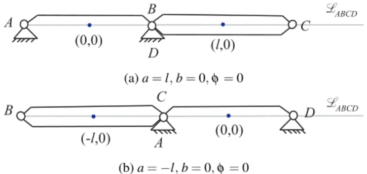
These operation modes are separated by two similar con-straint singularities shown in Fig. 6.
They can be algebraically represented by x1= x3= 4x22− l2x24= 0. From Eqn. (5), these singularities occur when b = 0, φ = 0 and a = ±l. These two configurations correspond to the two points Q1and Q2in the image space shown in Fig. 2. At a constraint singularity, any mechanism gains one or more degrees of freedom. Therefore, in case of the four-bar linkage with equal link lengths, the DOF at a constraint singularity is equal 2. In this configuration, points A, B, C and D are collinear and the corresponding motion type is a translational motion along the
D B C A (0,0) (l,0) L ABCD (a) a = l, b = 0, φ = 0 A C D B (0,0) (-l,0) L ABCD (b) a = −l, b = 0, φ = 0
FIGURE 6: CONSTRAINT SINGULARITIES OF THE FOUR
BAR MECHANISM.
normal to the line LABCDpassing through the four points A, B, Cand D combined with a rotation about an axis directed along z0and passing throughLABCD. Eventually, it is noteworthy that two actuators are required in order to control the end-effector in those constraint singularities in order to manage the operation mode changing.
DESIGN AND ANALYSIS OF A COMPLIANT FOUR-BAR MECHANISM
In this section, two compliant four-bar mechanisms, compli-ant four-bar mechanism-1 and complicompli-ant four-bar mechanism-2, are proposed based on the operation modes and constraint singu-larities of the four-bar rigid-body mechanism shown in Fig. 6b. Moreover, the desired motion characteristics of the compliant four-bar mechanism-2 are verified by nonlinear FEA simula-tions.
Design of a compliant four-bar mechanism
Based on the constraint singularity configuration of the four-bar rigid-body mechanism represented in Fig. 6, a com-pliant four-bar mechanism can be designed through kinemati-cally replacing the rigid rotational joints with compliant rota-tional joints [15]. Each of the compliant rotarota-tional joints can be any type compliant rotational joint such as cross-spring rotational joint, notch rotational joint and cartwheel rotational joint [3]. As shown in Fig. 7, a compliant four-bar mechanism, termed as the compliant four-bar mechanism-1, has been designed by replac-ing the four rigid rotational joints with three cross-sprreplac-ing rota-tional joints (RJ-0, RJ-1 and RJ-3) and one leaf-type isosceles-trapezoidal rotational joint that provides remote rotation cen-tre (RJ-2).
For small motion ranges, the compliant four-bar mechanism-1 has the same operation modes as the four-bar rigid-body mechanism shown in Fig. 6, via controlling the rotations of the Bar-1 and Bar-3. Moreover, both the compliant four-bar mechanism-1 and the four-bar rigid-body
Fig. 7 4R compliant mechanisms: (a) 4R compliant mechanism-1, and (b) 4R compliant mechanism-2 (a) Bar-0 Bar-1 Bar-2 Bar-3 Y X Z O RJ-0 RJ-1 RJ-3 RJ-2 α β (b) LH RJ-0 RJ-1 RJ-3 RJ-2 RJ-1 RJ-0 RJ-3 RJ-2 (a) Bar-3 Bar-0 Bar-1 Bar-2 Bar-2
FIGURE 7: COMPLIANT FOUR-BAR MECHANISM-1
Fig. 7 4R compliant mechanisms: (a) 4R compliant mechanism-1, and (b) 4R compliant mechanism-2 (a) Bar-0 Bar-1 Bar-2 Bar-3 Y X Z O RJ-0 RJ-1 RJ-3 RJ-2 α β LH RJ-0 RJ-1 RJ-3 RJ-2 RJ-1 RJ-0 RJ-3 RJ-2 (a)
L
R
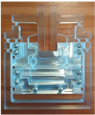
x y zFIGURE 8: CAD MODEL AND PROTOTYPE OF THE
COM-PLIANT FOUR-BAR MECHANISM-2
mechanism are plane motion mechanisms. Additionally, the three cross-spring rotational joints in the compliant four-bar mechanism-1 can be replaced by other types of rotational joints, which can form different compliant four-bar mechanisms. In this paper, cross-spring rotational joints are employed due to their large motion ranges while small rotation centre shifts. However, the leaf-type isosceles-trapezoidal rotational joint in the compliant four-bar mechanism-1 performs larger rotation centre shifts compared with the cross-spring rotational joint. Therefore, the compliant four-bar mechanism-1 can be improved by replacing the leaf-type isosceles-trapezoidal rotational joint with a cross-spring rotational joint. Such an improved design can be seen in Fig. 8, which is termed as the compliant four-bar mechanism-2. Note that, in Fig. 8, the RJ-0 and RJ-2, are traditional cross-spring rotational joints, while both the RJ-1 and the RJ-3 are double cross-spring joints introduced in this paper. Each of the rotational joints, RJ-1 and RJ-3, consists of two traditional cross-spring rotational joints in series. We specify that the Bar-0 is fixed to the ground and the Bar-2 is the output motion stage, also named coupler. The main body including rigid bars and compliant joints of the proposed compliant four-bar mechanism-2 can be fabricated monolithically using a CNC milling machine. It can also be 3D printed, and a 3D-printed prototype is shown in Fig. 8. The bars of the prototype have many small through holes, which can reduce material consumption and improve dynamic performance. Additionally, two cross-shaped parts are added to the actuated bars, which are used to actuate the mechanism by hands. The operation modes of the compliant four-bar mechanism-2 as output stage are analyzed in the following sections.
OPERATION MODES OF THE COMPLIANT FOUR-BAR MECHANISM-2
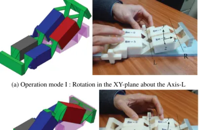
Like the four-bar rigid-body mechanism shown in Fig. 6b, the output motion stage (Bar 2) of the compliant four-bar mechanism-2 has multiple operation modes under two rotational actuations (controlled by input displacements α and β ), as shown in Fig. 8. However, the compliant four-bar mechanism-2 has more operation modes than the rigid counterpart. In order to simplify the analysis, let α and β be non-negative. A coordinate system is defined in Fig. 8, which is located on Bar 2. Based on this assumption, operation modes of the compliant four-bar mechanism-2 are listed below :
1. Operation mode I : Rotation in the XY-plane about the Axis-L, when α > 0 and β = 0, as shown in Fig. 9a,
2. Operation mode II : Rotation in the XY-plane about the Axis-R when α = 0 and β > 0, as shown in Fig. 9b, 3. Operation mode III : Rotation in the XY-plane about other
axes except the Axis-L and Axis-R, when α 6= β > 0, as shown in Fig. 9c, and
L R
x y
z
(a) Operation mode I : Rotation in the XY-plane about the Axis-L
R L
x y z
(b) Operation mode II : Rotation in the XY-plane about the Axis-R
R
L x y z
(c) Operation mode III : Rotation in the XY-plane about other axes except the Axis-L and Axis-R
R L
x y
z
(d) Operation mode IV : Pure translations in the XY-plane along the X and Y axes
FIGURE 9: OPERATION MODES OF THE COMPLIANT
FOUR-BAR MECHANISM-2
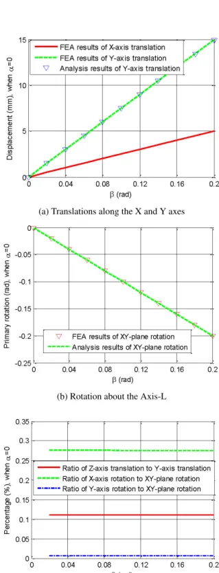
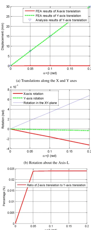
the X- and Y-axes, when α = β > 0, as shown in Fig. 9d. These operation modes are also highlighted through the printed prototype in Fig. 9. The primary motions of output motion stage (Bar-2) are the rotation in the XY plane and the translations along the X-and Y-axes; while the rotations in the XZ and YZ planes and translational motion along the Z-axis are the parasitic mo-tions that are not the interest of this paper. Moreover, the rota-tion angle in the XY-plane and the Y-axis translarota-tional morota-tion can be estimated analytically using Eqs. (17) and (18). However, the X-axis translational motion cannot be accurately estimated in such a simple way, because it is heavily affected by the shift of the rotation centres of the two cross-spring rotational joints [18]. The X-axis translational motion will be analytically studied in our future work, but will be captured by non-linear FEA.
θZ= α − β (17)
DY= 1
2(LB+ LR)(sin α + sin β ) (18) where θZ is the rotation in the XY plane and DY is the transla-tional displacement in the Y-axis. LBand LRare the geometrical dimensions of the reconfigurable mechanism at hand, as defined in Fig. 8.
SIMULATIONS OF THE OPERATION MODES
In order to verify the operation modes of the 4R compliant mechanism-2, nonlinear FEA software is employed to simulate the motions of the compliant four-bar mechanism-2. For the FEA simulations, let LBbe 100 mm, LRand LHbe 50 mm, the beam thickness be 1 mm, the beam width be 23 mm, the Poissons ra-tio be 0.33, and the Youngs modulus be 6.9 GPa. Commercial software, COMSOL MULTIPHYSICS, is selected for the non-linear FEA simulations, using the 10-node tetrahedral element and finer meshing technology (minimum element size 0.2 mm, curvature factor 0.4, and resolution of narrow regions 0.7). Note that the translational displacements of the Bar-2 along the X and Y axes are measured at the centre point of the top surface of the Bar-2 (termed as the interest point), as shown in Fig. 8. Results of the simulations are plotted in Figs. 10 to 13, and the following conclusions are drawn :
1. The maximum difference between the FEA results and the analytical results in terms of the Y-axis translation of the interest point (the centre of the top surface of the Bar-2) is tiny, which is less than 0.5% as shown in Figs. 10a, 11a, 12a and 13a.
2. The FEA results of the rotation in the XY-plane match the analytical results very well. The difference is less than 0.8 × 10⁻³ rad (0.5% of the maximum rotation angle), which is shown in Figs. 10b, 11b and 12b.
(a) Translations along the X and Y axes
(b) Rotation about the Axis-L
(c) parasitic motions (rotations about the X- and Y-axes and translation along the Z-axis)
FIGURE 10: FEA RESULTS FOR OPERATION MODE I
(a) Translations along the X and Y axes
(b) Rotation about the Axis-L
(c) parasitic motions (rotations about the X- and Y-axes and translation along the Z-axis)
(a) Translations along the X and Y axes
(b) Rotation about the Axis-L
(c) parasitic motions (rotations about the X- and Y-axes and translation along the Z-axis)
FIGURE 12: FEA RESULTS FOR OPERATION MODE III
(a) Translations along the X and Y axes
(b) Rotation about the Axis-L
(c) parasitic motions (rotations about the X- and Y-axes and translation along the Z-axis)
3. It can be seen from Figs. 10c, 11c, 12c, 13b and 13c that the parasitic motions are much smaller compared with the primary motions, for all the operation modes.
Overall, for all the operation modes of the compliant four-bar mechanism-2, the obtained analytical kinematic models are ac-curate enough to predict the rotation angle in the XY-plane and the translation displacement along the Y-axis, under specific in-put actuations. Additionally, the parasitic motions are much smaller than the primary motions, which ensures that the tiny effect of the parasitic motions on the primary motions can be ig-nored in an acceptable way. Therefore, it has been proved that the compliant four-bar mechanism-2 can be operated in the different operation modes with high accuracy.
A PROSPECTIVE APPLICATION AS A COMPLIANT GRIPPER
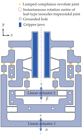
The reconfigurable compliant four-bar mechanism-1 shown in Fig. 7 is used to design a reconfigurable gripper as shown in Fig. 14. It can exhibit four grasping modes based on the ac-tuation of the linear actuator 1 (±α) or 2 (±β ) as displayed in Fig. 15. The first three grasping modes are angular, where the jaws of the gripper rotate about an instantaneous centre of rotation which is different for each grasping mode. The grip-per displays an angular grasping mode when α 6= 0, β = 0 as shown in Fig. 15a, α = 0, β 6= 0 as shown in Fig. 15b or when α < 0, β < 0 as shown in the right Fig. 15c. The parallel grasp-ing mode in which the jaws are parallel to one another is achieved when α > 0, β < 0 as shown in the left Fig. 15c. Thus, the re-configurable compliant gripper at hand unveils an ability to grasp a plethora of shapes unlike other compliant grippers in litera-ture that exhibit only one of these modes of grasping [14, 19]. Potential applications include micromanipulation and grasping lightweight and vulnerable materials like glass, resins, porous composites, etc. in difficult and dangerous environments. In ad-dition, it can be used for medical applications to grasp and ma-nipulate living tissues during surgical operations or as a gripper mounted on a parallel manipulator dedicated to fast and accurate pick-and-place operations. Figure 16 shows the prototype of the reconfigurable compliant gripper.
CONCLUSIONS AND FUTURE WORK
A novel idea of designing mobility-reconfigurable compli-ant mechanisms inspired by the constraint singularities of rigid body mechanisms was presented in this paper. A rhombus planar rigid four-bar mechanism was analyzed to identify its three op-eration modes and two constraint singularities separating those modes. The rigid joints were replaced by compliant joints to obtain two designs of a reconfigurable compliant four-bar mech-anism. The second design was found to be more accurate and
β
α
Linear actuator 2
Lumped compliance revolute joint Instantaneous rotation centre of leaf-type isosceles trapezoidal joint Grounded hole Gripper jaws Linear actuator 1
x
y
-+
+
FIGURE 14: A novel reconfigurable compliant gripper
less parasitic than the first one, which is verified by its non-linear FEA simulations in different motion modes. Moreover, the compliant four-bar mechanism was shown to have four oper-ation modes based on the particular actuoper-ation strategy unlike its rigid counterpart. A preliminary design of a compliant gripper has been designed based on the reconfigurable compliant four-bar mechanism introduced and studied in this paper.
In the future, we will focus on the analytical kinetostatic mod-elling of the reconfigurable compliant mechanism at hand while exploring appropriate applications. We also intend to design mobility-reconfigurable compliant mechanisms based on the constraint singularities of spatial rigid body mechanisms.
ACKNOWLEDGMENT
The authors would like to express their gratitude for the Ulysses 2016 grant between Ireland and France. Mr. Tim Powder and Mr. Mike O’Shea in University College Cork are appreciated
(a) Angular grasping mode 1 : α 6= 0, β = 0
(b) Angular grasping mode 2 : α = 0, β 6= 0
(c) Left : parallel grasping mode (α > 0, β < 0); Right : angular grasping mode 3 (α < 0, β < 0)
FIGURE 15: FOUR GRASPING MODES OF THE
COMPLI-ANT GRIPPER
FIGURE 16: Prototype of the reconfigurable compliant gripper
for their kind help in the 3D printed prototype.
REFERENCES
[1] Gallego, J. A., and Herder, J., 2009. “Synthesis meth-ods in compliant mechanisms: An overview.”. In ASME. International Design Engineering Technical Conferences and Computers and Information in Engineering Confer-ence, Vol. 7 of 33rd Mechanisms and Robotics ConferConfer-ence, Parts A and B. pp. 193–214.
[2] Olsen, B. M., Issac, Y., Howell, L. L., and Magleby, S. P., 2010. “Utilizing a classification scheme to facili-tate rigid-body replacement for compliant mechanism de-sign.”. In ASME. International Design Engineering Tech-nical Conferences and Computers and Information in En-gineering Conference, Vol. 2 of 34th Annual Mechanisms and Robotics Conference, Parts A and B. pp. 475–489. [3] Howell, L. L., 2001. Compliant mechanisms.
[4] Hao, G., and Li, H., 2015. “Conceptual designs of multi-degree of freedom compliant parallel manipulators com-posed of wire-beam based compliant mechanisms”. Pro-ceedings of the Institution of Mechanical Engineers, Part C: Journal of Mechanical Engineering Science, 229(3), pp. 538–555.
[5] Amine, S., Mokhiamar, O., and Caro, S., 2017. “Classifi-cation of 3T1R parallel manipulators based on their wrench
graph”. ASME. J. Mechanisms Robotics., 9(1).
[6] Maraje, S., Nurahmi, L., and Caro, S., 2016. “Operation modes comparison of a reconfigurable 3-PRS parallel ma-nipulator based on kinematic performance.”. In Proceed-ings of the ASME 2016 International Design Engineering Technical Conferences and Computers and Information in Engineering Conference. pp. 21–24.
[7] Nurahmi, L., and Caro, S., 2015. “Dimensionally homo-geneous extended jacobian and condition number.”. In The 2nd International Conference on Mechanical Engineering (ICOME 2015). pp. 3–5.
[8] Rubbert, L., Caro, S., Gangloff, J., and Renaud, P., 2014. “Using singularities of parallel manipulators for enhanc-ing the rigid-body replacement design method of compliant mechanisms”. ASME Journal of Mechanical Design, 136, pp. 051010–1–051010–9.
[9] Rubbert, L., Renaud, P., Caro, S., and Gangloff, J., 2014. “Design of a compensation mechanism for an active car-diac stabilizer based on an assembly of planar compliant mechanisms”. Mechanics & Industry, 15(2), pp. 147–151. [10] Zlatanov, D., Bonev, I. A., and Gosselin, C. M., 2002. Constraint Singularities as C-Space Singularities. Springer Netherlands, Dordrecht, pp. 183–192.
[11] Husty, M. L., Pfurner, M., Schr¨ocker, H.-P., and Brun-nthaler, K., 2007. “Algebraic methods in mechanism anal-ysis and synthesis”. Robotica, 25(6), Nov., pp. 661–675. [12] Nurahmi, L., Caro, S., Wenger, P., Schadlbauer, J., and
Husty, M., 2016. “Reconfiguration analysis of a 4-RUU parallel manipulator”. Mechanism and Machine Theory, 96, Part 2, pp. 269 – 289.
[13] He, X., Kong, X., Hao, G., and Ritchie, J., 2016. Design and Analysis of a New 7R Single-Loop Mechanism with 4R, 6R and 7R Operation Modes. Springer International Pub-lishing, Cham, pp. 27–37.
[14] Hao, G., and Hand, R. B., 2016. “Design and static test-ing of a compact distributed-compliance gripper based on flexure motion”. Archives of Civil and Mechanical Engi-neering, 16(4), pp. 708 – 716.
[15] Hao, G., Li, H., and Kavanagh, R. C., 2016. “Position-space-based compliant mechanism reconfiguration ap-proach and its application in the reduction of parasitic mo-tion.”. ASME. J. Mech. Des., 138(9), pp. 092301–092301– 13.
[16] Li, H., and Hao, G., 2015. “Compliant mechanism recon-figuration based on position space concept for reducing par-asitic motion.”. In ASME. International Design Engineer-ing Technical Conferences and Computers and Information in Engineering Conference, Vol. 5A of 39th Mechanisms and Robotics Conference. pp. 475–489.
[17] Bottema, O., and Roth, B., 2012. Theoretical Kinematics. Dover Books on Physics. Dover Publications.
[18] Zhao, H., Bi, S., and Yu, J., 2012. “A novel compliant
linear-motion mechanism based on parasitic motion com-pensation”. Mechanism and Machine Theory, 50, pp. 15 – 28.
[19] Hao, G., and Kong, X., 2012. Conceptual design and mod-elling of a self-adaptive compliant parallel gripper for high-precision manipulation.