HAL Id: hal-02102852
https://hal.archives-ouvertes.fr/hal-02102852
Submitted on 17 Apr 2019
HAL is a multi-disciplinary open access
archive for the deposit and dissemination of
sci-entific research documents, whether they are
pub-lished or not. The documents may come from
teaching and research institutions in France or
L’archive ouverte pluridisciplinaire HAL, est
destinée au dépôt et à la diffusion de documents
scientifiques de niveau recherche, publiés ou non,
émanant des établissements d’enseignement et de
recherche français ou étrangers, des laboratoires
Model-Based System Engineering in Practice: Document
Generation - MegaM@Rt2 Project Experience
Andrey Sadovykh, Adnan Ashraf, Alessandra Bagnato, Dragos Truscan,
Pierluigi Pierini, Hugo Bruneliere, Orlando Avila-Carcia, Wasif Afzal
To cite this version:
Andrey Sadovykh, Adnan Ashraf, Alessandra Bagnato, Dragos Truscan, Pierluigi Pierini, et al..
Model-Based System Engineering in Practice: Document Generation - MegaM@Rt2 Project
Experi-ence. 14th Central and Eastern European Software Engineering Conference Russia (CEE-SECR’18),
Oct 2018, Moscow, Russia. pp.1-6, �10.1145/3290621.3290633�. �hal-02102852�
Model-Based System Engineering in Practice: Document Generation
- MegaM@Rt2 Project Experience
Full paper
Andrey Sadovykh Softeam, 75016 Paris, France [email protected] Innopolis University, 420500 Innopolis,
Respublika Tatarstan, Russia, [email protected]
Adnan Ashraf
Åbo Akademi University, 20500 Turku, Finland
Alessandra Bagnato Softeam, 75016 Paris, France [email protected]
Dragos Truscan
Åbo Akademi University, 20500 Turku, Finland
Pierluigi Pierini Intecs, 56121 Pisa, Italy [email protected]
Hugo Bruneliere IMT Atlantique, LS2N (CNRS) & ARMINES, 44000 Nantes, France [email protected] Orlando Avila-Carcia
Atos, 38110 Tenerife, Spain [email protected]
Wasif Afzal
Mälardalen University, Sweden [email protected]
ABSTRACT
MegaM@Rt2 project is a collaborative initiative of the ECSEL Joint Undertaking under Horizon 2020 EU programme. The project regroups 26 partners from 6 different European countries who jointly address challenges of engineering modern cyber-physical systems by using model-based engineering methods. Since it is a model-based project, we adopted a similar approach for dealing with requirements analysis, architecture, design, roadmap planning and development status checking. In these tasks, document generation methods were particularly useful to create a set of “live” reference specifications and contractual reports. We believe that these methods perfectly demonstrate relevant benefits of the model-based approach and are applicable to many other contexts. Document generation has several challenges, since the produced documents should address several goals and target different audience. Hence, we describe this approach in detail in this paper in the form of an experience report.
In essence, the MegaM@Rt2 project had a rather trivial task to document inception phase of the project. The challenge arises from the scale of the project, we had to deal with hundreds of requirements from completely different users, hundreds of features of 29 tools, which had to be mapped to those requirements in order to analyze a gap and devise a roadmap for a consistent tool chain. With limited resource on technical coordination we had to be extremely efficient and thus we adopted a model-based approach that we describe in this paper. The paper should be helpful to project managers and architects who wish to discuss on model-based approaches from a practical side.
CCS CONCEPTS
• Software and its engineering → Software systems models;
Model-driven software engineering
KEYWORDS
document generation, requirements, model-based system engineering, model-driven software engineering, UML, SysML, traceability.
1 INTRODUCTION
MegaM@Rt2 is a three-years project, funded by European Components and Systems for European Leadership Joint Undertaking (ECSEL JU) under the H2020 European program, that started in April 2017 [4, 5, 9, 11]. The main goal is to create an integrated framework incorporating methods and tools for continuous system engineering and runtime validation and verification (V&V). The underlying objective is to develop and apply scalable model-based methods and tools, in order to provide improved productivity, quality, and predictability of large and complex industrial systems.
One of the main challenges is to cover the needs coming from diverse and heterogeneous industrial domains, going from transportation and telecommunications to logistics. Among the partners providing case studies in the project, we can cite Thales, Volvo Construction Equipment, Bombardier Transportation and Nokia. These organizations have different product management and engineering practices, as well as regulations, commercial and legal constraints. This results in a large and complex catalogue of requirements to be realized by the architecture building blocks at different levels of abstraction. Thus, the development of the
2
MegaM@Rt2 framework is based on a feature-intensive architecture and on a related implementation roadmap.
The MegaM@Rt2 framework plans to integrate more than 29 tools implementing the above-mentioned methods and satisfying requirements of the case studies. The tool features are grouped into three complementary conceptual tool sets:
· MegaM@Rt2 Systems Engineering Tool Set regroups
a variety of current engineering tools featuring standard and domain specific languages and methodologies, e.g.: AADL, EAST-ADL, Matlab/Simulink, AUTOSAR, Method B or Modelica, SysML and UML, in order to precisely specify both functional and non-functional properties. Moreover, system level V&V and testing practices are also supported by this tool set, in order to assess the correctness of the model.
· MegaM@Rt2 Runtime Analysis Tool Set seeks to
extensively exploit system data obtained at runtime. Different methods for based V&V and model-based testing (MBT) are rethought and/or extended for runtime analysis. Model-based monitoring allows to observe executions of a system (in its environment) and to compare it against the executions of corresponding model(s). Monitoring also allows a particular system to be observed under controlled conditions, in order to better understand its performance.
· MegaM@Rt2 Model & Traceability Management
Tool Set is a key part of the framework as it is
dedicated to support traceability between models across all layers of the system design and execution (runtime). This can go from highly specialized engineering practices to low-level monitoring. Relying on the unification power of models, it should provide efficient means for describing, handling and keeping traceability/mapping between large-scale and/or heterogeneous software and system artefacts.
In the context of the Model-driven Architecture (MDA) and Model-based approaches, developed and deployed in the last two decades, automated document generation was foreseen as one of the primary benefits [1, 6]. Indeed, models as the first-class entities of the engineering process should contain all the necessary information for the design documentation. Automated document generation was one of the first benefits offered by the Model-driven Architecture (MDA) [1, 6]. Indeed, models as the first-class entities of the engineering process should contain all the necessary information for the design documentation. However, several related challenges arise. First, the software architecture team should decide the right organization for the global architecture model. Second, it should be carefully planned what level of details is appropriate for the design of the individual contributions. Third, it should be considered that the architecture model will be used during the project's timeframe for numerous purposes, thus it needs to accommodate unforeseen changes in methodology. Fourth, several documents need to be generated by extracting the relevant information from all over the architecture model.
In this paper, we present our experience on providing and using model-based tool support for on providing model-based tool support for generating documentation necessary for documenting the project (e.g, via deliverables) with respect to the definition of MegaM@Rt2 framework architecture, of the solution to be implemented in the context of the project and of the corresponding roadmap for the development of architecture components throughout the project. In particular, we focus on the document generation challenges and practical solutions to these.
2 DOCUMENT GENERATION CHALLENGES
Documentation is an inherent part of any engineering process that contributes to quality, maintainability and reusability of produced systems. Arguably, there is no clean engineering process without a proper documentation. As an example, ISO supports the software engineering process with a set of standards dedicated to different audience such as designers, developers, testers, managers, suppliers and agile team members [7, 8]. The famous ISO 9001 defines a set of mandatory documents including e.g. the requirements specifications. Another popular set of standards is European Space Agency system engineering standards ECSS-E-40 / ECSS-Q-80, also strongly requiring a set of documents and reports to accompany the engineering process on various levels. This includes software-requirement analysis, top-level architectural design, design of software and hardware items, test reports, and user documentation. These documents include mandatory parts that are particularly important on various stages of the process. Many times, the documentation is also a contractual obligation or a part of a certification.
In the meantime, the documentation is an extremely tedious task. The documentation should be readable, useful, consistent and always up-to-date. These characteristics are very difficult to achieve. Documentation is a mechanical production of specifications that often cannot follow the pace of engineering work. Thus, many developers consider this as a useless task that can sometimes contribute to confusing situations. Consequently, agile approaches encourage developers to limit the documentation effort to bare minimum – notes in code should be enough. While such approaches can be appropriate for small-to-medium size projects, they are often not relevant or even counterproductive in larger and/or critical projects.
Model-driven and model-based approaches suggest generating documents from a system model by extracting relevant information such as diagrams, textual descriptions and dependencies. The major benefit is the possibility to regenerate the documents when needed, thus having in place always updated “live” documents that can follow precisely the best standards. The main challenge is about defining the right generation templates for multiple documents:
· Various parts of the model are used in different documents. Requirements in the requirement specifications. Interface definitions in analysis documents;
· Level of details varies depending on the document type and the audience;
· The choice of the “target platform” for document generation, e.g. MS Word or HTML would require changes in structure and style of the documents. Word documents are usually supposed to be read sequentially, while web pages should be easy for navigation in sporadic manner.
Considering the above-mentioned challenges, it is essential to structure and define the model properly as well as to define how the information is shared and used in different documents depending on its goal and intended audience. In order to deal with these challenges in a practical way we suggest the following steps: · Define a structure of an architecture model based on the most important information to be shared within the team at the current stage of the project;
· Define a structure of reports, which are supposed to benefit of generation;
· Define which information should be extracted from the model, in order to contribute to the report;
· Develop tool support.
In the following sections, we will further describe our approach based on the MegaM@Rt2 project experience.
3 MEGAM@RT2 ARCHITECTURE MODEL
SPECIFICATION
The architecture model had to support the inception phase of the MegaM@Rt2 project and a set of contractual reports to be delivered during the project. At this phase, it was essential to lay down the user requirements coming from case study partners, list the available tools from the consortium, outline the gaps in tool features with regards to the user requirements, track the tool providers plans to deliver the required features, prepare for tool sets integration.
We adopted a practical approach for the architecture specification that is particularly suited to collaborative projects such as MegaM@Rt2, which integrates tools coming from many parties. The authors are well informed about of a wealth of notations and methods for engineering process modelling such as OMG ESSENCE, SPEM, BPMN as well as The Open Group ArchiMate. We participated in standardization and implemented several solutions based on above-mentioned notations. In the project context, our goal was to avoid ambiguity, reduce the learning curve and simplify adoption for 60+ engineers who work on the project. Hence, as a modelling language, we took a Systems Modelling Language (SysML) [2] subset for requirements specification and a Unified Modelling Language (UML) [3] subset for the high-level architecture specification. We have picked the requirements concept from SysML, while from UML we borrowed components, interfaces, nodes, aggregation/composition, dependencies, generalization and realization. We believe that these concepts are the most familiar to a large audience of architects.
As for the model structure, we split the architecture model in several parts and divided the responsibilities among the different Tool Set (TS) leaders, tool providers and case study providers. The following terminology and subsystems has been defined:
Requirements/Purposes level, specified in SysML:
· Case study requirements - specified by case study partners. These are the user requirements, which we imported for traceability purposes.
· Framework requirements - specified by TS leaders. We grouped the tools by consortium in conceptual tool sets described in Section 1. The framework requirements summarized the users feature requirements related to those groups.
· Tool purposes - specified by tool providers. Tool purposes in our terminology are the tool requirements that correspond to available features or to features be developed. Each tool provider specified the baseline features and the features to be developed as a contribution to the MegaM@Rt2 project.
· Requirements traceability - the gap analysis and roadmap specification require that the user requirements are linked to the tool features. TS leaders and tool providers established those traceability links in the model.
Architecture level, specified in UML:
· Framework - TS leaders specified conceptual tool sets in a form of component diagrams.
· Tool set – tool providers described their tools individually with diagrams following a common template.
· Common interfaces – as a part of tool sets integration preparation we asked tool providers to list the support exchange forms and APIs. This helps to identify tools that can potentially work together.
· Common deployment frameworks – again as a part of tool sets integration, we explored possibilities for common deployment of tools in the frame of the tool sets.
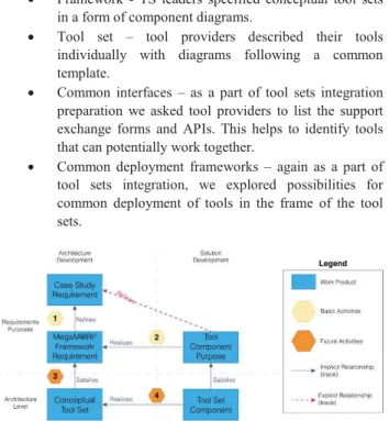
Figure 1: Overview of the Architecture and Development process in MegaM@Rt2.
The approach is further outlined in Fig. 1, where we present the steps to define the MegaM@Rt2 framework architecture. At the step 1, the Tool Set leaders summarized and extracted the essence and commonalities from the users’ requirements provided by the case study partners. This resulted in a MegaM@Rt2 Framework Requirements. At the step 2, tool providers linked
4
purposes (features) to those generalized user requirements the MegaM@Rt2 Framework Level. Therefore, by the indirect traces between framework requirements and tool purposes (features) we were able to provide the gap analysis, identifying the unsupported user requirements and the relevant mitigation measures e.g. additional tools, new purposes (features) for provided tools, etc.
For further analyses in order to prepare development and integration of coherent tool sets, we devised a conceptual architecture with the steps 3 and 4. The MegaM@Rt2 Framework is regrouped in Conceptual Tool Sets (Section 1). At the step 3 we identified the relevant interfaces to satisfy framework requirements and subordinate tool sets to further detail the implementation. Then, at the step 4, for each Conceptual Tool Set Component we specify concrete tool set components to realize the desired functionality. Those concrete tool set components expose features and satisfy purpose requirements that include the release milestone indications for the roadmap definition.
3.1 Requirements modeling
In our approach, requirements originated from different sources, i.e. from 9 case study providers and 22 tool providers. In order to have a uniform approach for requirement specification that would facilitate gap analysis and roadmap identification, we defined requirement templates that were used to define the expected properties to be collected, such as criticality for the case study requirements and planned release date for tool purposes.
We edited requirements in both diagram view and tabular view (see Fig. 2) in the Modelio tool [12]. The requirements were manually edited or automatically imported from other documents, e.g. MS Excel.
Figure 2: Example: Requirements editing.
3.2 Architecture modeling.
At the architecture level, we used Class and Deployment diagrams. We limited modelling to a subset of UML to enforce the common understanding of the architecture and simplify editing. In particular, we chose to use UML Components, Interfaces, Associations, Generalizations and Dependencies.
For tool components, we set a template for the architecture specification that included class diagram to specify functional interfaces, tool component subordinates and the relation to the conceptual tool set in the framework, and deployment diagrams to identify the execution environment of the tool component. In addition, Package diagrams have been used to define the high-level structure of the MegaM@Rt2 framework architecture. For
instance, Fig. 3 shows that the MegaM@Rt2 framework architecture is composed of three parts corresponding to the three complementary conceptual tool sets of the project. System Engineering, Runtime Analysis, and Model and Traceability Management, respectively.
Figure 3: Example: Editing architecture and documentation with Modelio.
In Modelio, the documentation (Fig. 3) can be added in the textual notes or attached as separate documents. Both plain text and rich text notes are supported. In our work, we deliberately restricted editing to plain text notes to make sure that the generated documents are formatted correctly.
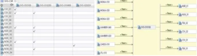
3.3 Requirements traceability.
Once the requirements had been specified, for each tool component we defined a traceability matrix to link case study requirements to framework requirements, and respectively framework requirements to tool purposes as described by the steps 1 and 2 of the modelling approach in Fig. 1. This allowed us to use instant traceability diagrams, as the one in Fig. 4, to visualize the whole set of dependencies for a given requirement. This has been beneficial not only for the requirement analysis and toolset integration planning, but also for identifying common interfaces for tool components and visualize gaps for the requirements analysis.
Figure 4: Example: Traceability links among the tool set, framework and case study requirements.
4 STRUCTURING MEGAM@RT2 REPORTS
The information extracted from the above-mentioned model is used to generate the contents of different deliverables in the project, each focusing on different perspectives corresponding to
various tool sets and thematics. The following deliverables have been already published on the project website [13]:
· D1.2 Architecture specification and roadmap – initial version;
· D1.4 Architecture specification and roadmap – final version;
· D2.2 MegaM@Rt design tool set specification; · D2.3 MegaM@Rt design tool set – initial version; · D3.2 Specification of the MegaM@Rt Runtime
Analysis tool set;
· D3.3 MegaM@Rt Runtime Analysis tool set – initial version;
· D4.2 Specification of the Model Management & Traceability tool set;
· D4.3 Model Management & Traceability tool set – initial version;
These documents included the sections that where generated based on the information extracted from the models. In particular, the all specifications included tables for features, diagrams for interfaces, subordinates and deployment.
It was particularly helpful to extract the traceability links information in a form of matrix tables that enabled us to visualize the relations between user requirements and tools, which provide the corresponding features.
Figure 5: Example: D3.2 Traceability and release plan excerpt for framework requirements and corresponding concrete
tools.
On the later stages of the project we linked the tools features to the release milestones and their status in order to track the progress (Fig. 5).
5 TOOLING APPROACH FOR MODELING
AND DOCUMENT GENERATION
Appropriate tooling support is important for the success of the model-driven engineering process as shown in Fig. 1. In order to provide tool support for our architecture specification approach, we selected the Modelio and Constellation tools [10, 12] provided by one of the project participants, SOFTEAM.
When collecting inputs from 50 users, it was important to provide guidelines and diagram templates. Otherwise, the integration work may have become extremely challenging. As such, we defined a set of template diagrams both for specifying requirements and for collecting tool purposes. Users were able to clone these templates inside the model to describe their concrete tools.
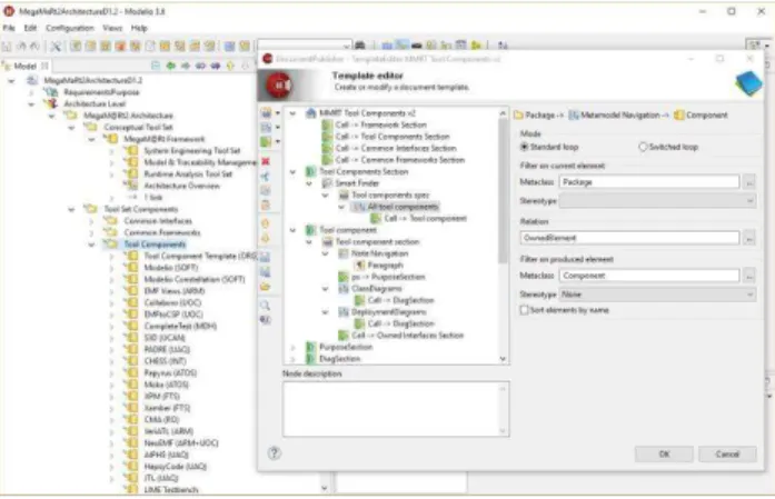
Modelio offers fairly flexible model query and document generation facilities that were used for editing and maintaining four specifications in the project. The template editor (Fig. 6) was particularly useful to implement custom extraction of model elements in order to create specific sections of the documents. In the example below, the template specifies that the generator will search for a Tool Components package, look at all the UML components to generate a tool section. This document section included an introductory paragraph, a “Purpose” subsection, and subsections for all class and deployment diagrams as well as a section on the owned interfaces.
Figure 6: Example: Custom document generation template for individual tools section.
When editing the architecture model, it is quite useful to see the generation result. Along with developing custom document templates, we integrated the document generation to the Modelio interface. This way, regular users could call the document generation directly from the tool using a context menu (Fig. 7). The new customized document templates can be done by users without programming skills with the help of Modelio visual editors.
Figure 7: Example: Architecture document generated with Modelio Document Publisher.
6
The effort required to develop templates was insignificant comparing to the time required to devise the documents structure and collect the inputs from project partners in a model form.
6 CONCLUSIONS
In this paper, we presented the model-based documentation approach that we adopted at the inception stage of the MegaM@Rt2 project. Our approach enforced the coordination and collaboration among many different stakeholders, and thus the manageability of this complex project.
The main benefit of our model-driven approach is that all information was collected from different stakeholders and stored using a centralized model. In this paper we showed how we can use the principles of model-driven development where the model is the first-class citizen and different artefacts are generated from it. In our case, the generated artefact was the documentation of the project. The main benefit of having the model as a source of information, was that we could generate documentation (ie., deliverables) that focused on different perspectives of the MegaM@RT2 framework, at different levels of abstraction and using different document formats. This also, allowed to bridge the gap between the experienced modeling users and less experience ones which could at any moment generate the documentation they needed related to a given aspect of the project.
Overall, the experience with this approach was mostly positive, and the approach will be further used 1) in other architecture deliverables at later stages of the project and 2) as the reference point for the partners in the project at any moment in time. Further on the positive site, this approach has already contributed to delivery of 8 contractual reports in the MegaM@Rt2 projects. The approach has been highly praised by the expert as the project review. Finally, we received interest from H2020 DataBio and ITEA REVAMP projects to apply a similar technique. Currently, these projects have partially adopted the document generation as well.
ACKNOWLEDGEMENT
This project has received funding from the Electronic Component Systems for European Leadership Joint Undertaking (ECSEL JU) under grant agreement No. 737494. This Joint Undertaking receives support from the European Union's Horizon 2020 research and innovation program and from Sweden, France, Spain, Italy, Finland and Czech Republic.
REFERENCES
[1] OMG: Model Driven Architecture (MDA) Guide rev. 2.0, http://www.omg.org/cgi-bin/ doc?ormsc/14-06-01
[2] OMG: OMG Systems Modeling Language (OMG SysML), Ver. 1.4, http://www.omg.org/ spec/SysML/1.4/
[3] OMG: Unified Modeling Language (UML), Ver. 2.5, http://www.omg.org/spec/UML/2.5/
[4] Afzal, Wasif, et al. "The MegaM@Rt2 ECSEL Project: MegaModelling at Runtime—Scalable Model-Based Framework for Continuous Development and Runtime Validation of Complex Systems." Digital System Design (DSD), 2017 Euromicro Conference on. IEEE, 2017.
[5] Bruneliere, Hugo and Mazzini, Silvia and Sadovykh, Andrey. "The MegaM@Rt2 Approach and Tool Set." DeCPS Workshop, 22nd International Conference on Reliable Software Technologies-Ada-Europe 2017. 2017.
[6] Di Ruscio, Davide and Paige, Richard F. and Pierantonio, Alfonso: Guest editorial to the special issue on success stories in model driven engineering. Science of Computer Programming, Volume 89 (Part B): 69–70, 2014. [7] ISO/IEC/IEEE 29148: Systems and software engineering - Life cycle
processes - Requirements engineering. ISO/IEC/IEEE. Nov. 2011. [8] ISO/IEC 25010: Systems and software engineering - Systems and software
Quality Requirements and Evaluation (SquaRE) - System and software quality models. ISO/IEC. March 2011
[9] MegaM@Rt2 project web-site, https://megamart2-ecsel.eu/, last visited on July 20, 2018.
[10] Desfray, Philippe. "Model repositories at the enterprises and systems scale: the modelio constellation solution." Information Systems Security and Privacy (ICISSP), 2015 International Conference on. IEEE, 2015. [11] Afzal, Wasif, et al. The MegaM@Rt2 ECSEL project: MegaModelling at
Runtime – Scalable model-based framework for continuous development and runtime validation of complex systems, Microprocessors and Microsystems, Volume 61: 86-95, 2018.
[12] Modelio MDE workbench by ModelioSoft, web-site https://www.modeliosoft.com/en/, last visited on July 19, 2018 [13] MegaM@Rt2 deliverables web-page,