HAL Id: hal-01008964
https://hal.archives-ouvertes.fr/hal-01008964
Submitted on 31 Jan 2019
HAL is a multi-disciplinary open access
archive for the deposit and dissemination of
sci-entific research documents, whether they are
pub-lished or not. The documents may come from
L’archive ouverte pluridisciplinaire HAL, est
destinée au dépôt et à la diffusion de documents
scientifiques de niveau recherche, publiés ou non,
émanant des établissements d’enseignement et de
Strength of inflatable fabric beams at high pressure
Christian Wielgosz, Jean-Christophe Thomas, Pascal Casari
To cite this version:
Christian Wielgosz, Jean-Christophe Thomas, Pascal Casari. Strength of inflatable fabric beams
at high pressure. 43rd AIAA/ASME/ASCE/AHS/ASC Structures, Structural Dynamics, and
Ma-terials Conference, Structures, Structural Dynamics, and MaMa-terials, 2002, Denver, United States.
�10.2514/6.2002-1292�. �hal-01008964�
STRENGTH OF INFLATABLE FABRIC BEAMS AT HIGH PRESSURE
C. Wielgosz, J.C. Thomas, P. Casari
Laboratoire de Génie Civil de Nantes – Saint Nazaire Faculté des Sciences et des Techniques, Université de Nantes 2, rue de la Houssinière, BP 92208 - 44322 Nantes Cedex 03, France.
ABSTRACT
Inflatable structures made of modern textile materials can be inflated at high pressure in order to be used as strong building elements. The aim of the paper is to present results from research on the mechanics of highly inflated structures. Experimental, analytical and numerical studies on the behavior of inflatable fabric beams are displayed. We will first describe experimental studies on two kinds of inflatable prototypes: flat panels and tubes. Experiments show that their behavior is a linear combination of yarns and beams shapes. The usual theory of collapse analysis is then applied to the computation of wrinkling loads of these fabric beams. The second section of the paper is devoted to build a new inflatable beam theory and to show that the compliance of the inflatable beams is the sum of the beam compliance and of the yarn compliance. A new inflatable beam finite element is developed in the third section and used to compute deflections of hyperstatic beams. Our first results on the buckling of inflatable panels are displayed in the last section. Comparisons between experimental and analytical results are shown and show that this new theory on the mechanical strength of inflatable structures at high pressure is satisfactory.
INTRODUCTION
This paper presents results from research on the mechanics of inflatable structures at high pressure. Such structures are not new and a lot of inflatable structures are used by the industry: temporary buildings, boats, pools, space antennas, life jackets, etc. Moreover they have many interesting properties: they are light, easily folding and present reversible behavior after failure (they come back to their initial position after unloading). Inflation causes tension pre-stress in the walls and in the yarns of the structures. This pre-stress is proportional to the pressure and ensures an important mechanical strength. Generally, the inflation pressure is lower than 105 Pa because the structures are built with
low strength materials. Development of new types of
structures making full use of performance
characteristics of modern textile materials will be possible by means of an available theory of their
behavior when pressure reaches more than 106 Pa.
A high pressure in inflatable structures is interesting from the following point of view: wrinkling and/or limit load is proportional to the applied pressure1. We must therefore use a high pressure if we want a good mechanical strength of inflatable structures.
Unfortunately there is few results on the deflections of
inflatable structures. Comer and Levy2, and more
recently Main & all3 have studied inflatable fabric tubes and calculated the deflections of cantilever structures by using the usual beam theory. We will show that these studies should be improved. The obvious reason is that in a beam theory, the values of the deflections depend only on the flexural rigidity of the beam. Pressure doesn’t appear in the beam solution, and it seems clear that an inflated beam at an extremely low pressure has very large deflections. Deflection values are close to experimental ones when the pressure is low, but go far
from reality at high pressure4. Moreover in a yarn
theory deflections are independent of the material constitutive law and this is irregular. We will show that in fact the deflections of inflatable structures are a linear set of yarn and beam deflections. Given that these deflections are inversely proportional to the constitutive law and to the applied pressure, we have a second reason to inflate highly the structures and to use high performance materials.
In the first section of the paper we will describe experimental work and show that inflatable beams cannot be viewed as ordinary plates or beams, because their deformation pattern is quite different. Experiments show that they behave like yarns when the pressure is low, like yarns and beams at high pressure, and once again like yarns or mechanisms when the applied load reaches the collapse load. Moreover experimental work shows that the section’s rotation of the beam is not orthogonal to the average fiber and implies that an usual beam theory can’t be used to calculate deflections of inflatable beams when the pressure is high.
The first experimental results are used in the second section in order to make an analogy between the usual theory of limit analysis of plastic beams, and the particular behavior of inflated beams when the collapse load is reached. We will show that a suitable definition of the limit bending momentum allows the use of classical results in limit analysis.
A new inflated beam theory is constructed in the third section in order to provide simple analytical formulas for deflection values of cantilever inflated beams. Equilibrium equations are written in the deformed state of the beam to take the geometrical stiffness and the following forces into account, and a Timoshenko’s beam theory is used. We will show that the deflection of the beam is simply the sum of the theoretical deflections given by the beam and the yarn theories.
In the fourth section of this paper, we will build an inflatable beam finite element, able to give good values of the displacement field for hyperstatic beams or in structures made of inflatable beams. The inflatable beam theory implies that the compliance matrix of a cantilever inflated beam is simply obtained by adding the usual matrixes of yarns and beams. This matrix is then used to calculate the stiffness matrix of the free finite element by applying the usual theory of the equilibrium finite element method. This new element is then implemented in a finite element software. We will then compare results obtained with this new finite element to experimental, analytical and numerical results All these comparisons prove the accuracy of this theory on the mechanical strength of inflatable beams at high pressure and the efficiency of this inflatable finite element.
Our first results on the buckling of an inflated panel are displayed in the last section. Obviously, an extension of the theory will be necessary in order to predict buckling occurring in compression loads.
EXPERIMENTAL STUDY ON INFLATABLE PANELS AND TUBES
Experimental results on inflatable panels
The tested panels are prototypes constructed by Tissavel Inc. They are made of two parallel-coated woven fabrics connected by yarns and a cross section of these panels is shown Figure 1. The yarns density is enough to ensure the flatness of the fabric structure. Yarns are made of high strength polyester: its membrane modulus is about of 650000 N/m
Figure 1. Cross section of the panels
The panel’s behavior depends on the inflation pressure p that leads the fabrics and the yarns to be prestressed and then to support local compression loads. Experimental study has been realised for two kinds of boundary conditions: simply supported panels and panels clamped at their two ends. Panels are loaded by a concentrated force F applied at the mid span of the
beam. The width and height are named b, h and
O
is thehalf span of the beam. The typical shape of an inflated panel is shown figure 2.
Figure 2. Deformed pattern of a simply supported inflated panel.
For such deformations, when the pressure is low, large straight parts appear between points of loading. When the pressure is higher, straight parts are shorter and a wider curved zone appears. The panel has therefore a behavior that is similar to that of a tensioned yarn when the pressure is low and to that of a beam when the pressure is high, and once again to that of a yarn (or a mechanism) when the applied load reaches the collapse load. Experimental deflection curves for low and high values of the inflation pressure are shown figure 3.
3 -0,06 -0,04 -0,02 0 0 0,4 0,8 1,2 1,6
Abscissae of the panel (m)
D e fl e c ti o n ( m ) 300 kPa - 250 N 50 kPa - 60 N
Figure 3. Deflection curves for low and high pressure on a Clamped-Clamped panel
Experimental results on inflatable tubes
Tubes are also prototypes made of Ferrari’s pre-stressed fabrics. High characteristics fabrics are also used: the membrane modulus is 300000 N/m.
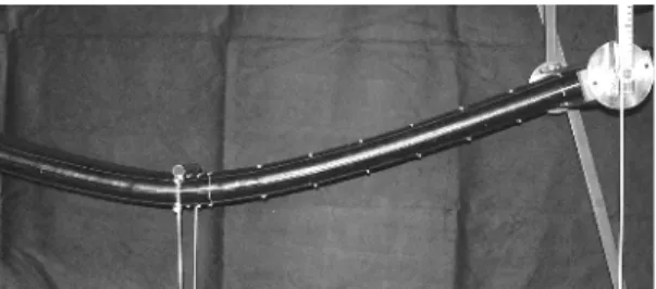
Experimental study has also been realized for two kinds of boundary conditions: simply supported tubes and clamped tubes. The radius of the tube is named R. Typical shape of simply supported tubes is shown figure 4.
Figure 4. Deformed pattern of a simply supported inflated tube
Similar statements can be done on the bended shapes of the tubes, but with less straight parts between points of loading. In fact, for panels, the influence of shear stresses along the sides can be neglected regarding the stiffness of the two pre-stressed membranes at the top and bottom of the panel. This is not true for inflated tubes; shear stresses play an important role in the behavior of the beam. Experimental deflection curves for low and high values of the inflation pressure are shown figure 5. -0,09 -0,06 -0,03 0 0 0,5 1 1,5 2
Abscissae of the tube (m)
D e fl e c ti o n ( m ) 100 kPa - 150 N 300 kPa - 350 N
Figure 5. Deflection curves of a simply supported tube for low and high pressure
All these experimental results prove that inflatable beams behave successively like yarns or beams, and that their deformation pattern depends mainly on the inflation pressure and on the applied load.
WRINKLING AND COLLAPSE LOADS
Two kinds of results are interesting values from an engineering point of view: results on the wrinkling or collapse loads, and values of the deflections for a given load. We will begin with the first kind of results because these values can simply be obtained from the theory of shakedown analysis of beams: the deformation pattern of the inflated beam near it’s wrinkling / collapse load looks like a “Wrinkling load” phenomenon defined when the local resultant stress in the fabric begins to cancel in a side of the beam. Collapse load is defined when the structure becomes a mechanism. An important property of inflatable structures is due to the fact that this collapse is reversible: after unloading, inflatable structures come back to their initial position.
Shakedown analysis of plastic beams is well known5.
When plasticity appears on the inner or outer fibers of a simply supported beam loaded at its mid span, the load F0 is given by:
l
0 0 4M
F= (1)
Where M0 is the maximum elastic momentum (also
equal to the momentum which gives the beginning of the plastic process) and
O
is the length of the beam. When the load is increased, a plastic zone grows until a plastic hinge appears and the section of the beam isentirely plastified. The collapse load F1 is given by the
same formula by replacing M0 by the total or plastic
l
1 1 4M
F= (2)
In the case of our inflated fabric beams, we can make the analogy between the beginning of plasticity and the apparition of an area where the stresses in the fabric cancels. Development of the plastic area is analogous to the expansion of a pneumatic hinge, and when the external load equals the collapse load, the pneumatic hinge has no strength. The beam becomes a mechanism and the collapse load is reached. The main difference between plasticity and the mechanical behavior of inflatable beam provides from the fact that plasticity gives residual strains and that shakedown is reversible for inflatable structures: they come back to their initial position after unloading.
Wrinkling and collapse loads of panels
Following results depend on the definition of the bending moments M0 and M1. Let’s consider a small element of the panel. Ni and Ns denote the resultant stress respectively in the lower and upper membrane.
Ns
Ni Ni
Ns h
The bending momentum results mainly from the difference between the stresses in the two membranes,
(
Ni NS)
2 h
M= − (3)
and these stresses are equilibrated by the internal pressure. h b h pb N N 2 i S + = + (4)
The wrinkling load is obtained when one of the resultant stresses cancels, for instance Ns = 0. The first bending momentum is therefore equal to:
) h b ( 2 h pb M 2 2 0 + = (5)
The second bending momentum is defined when the pneumatic hinge is entirely unwrapped. One of the resultant stress is therefore equal to the whole load due to the internal pressure and we have:
2 pbh M
2
1= (6)
Collapse loads can therefore be easily obtained by using the theory of limit analysis. In the case of our two experiments on hyperstatic beams, the collapse loads are respectively given by5. For a simply supported – clamped beam, we have:
l
1 1 6M
F= (7)
and for a clamped-clamped beam:
l
1 1 8M
F= (8)
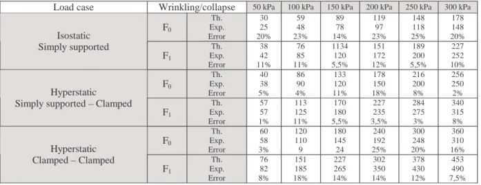
Comparisons between experimental and theoretical results are given in Table 1, for three kinds of boundary conditions.
One can see that errors between experimental and theoretical results are lower than 25% for wrinkling load and below 18% for collapse load. The wrinkling load is identified as a beginning of non-linearity on the load displacement curve of the panel response under static load.
5
Table 1: Wrinkling/collapse load on panel with various boundary conditions
Load case Wrinkling/collapse 50 kPa 100 kPa 150 kPa 200 kPa 250 kPa 300 kPa
F0 Th. Exp. Error 30 25 20% 59 48 23% 89 78 14% 119 97 23% 148 118 25% 178 148 20% Isostatic Simply supported F1 Th. Exp. Error 38 42 11% 76 85 11% 1134 120 5,5% 151 172 12% 189 200 5,5% 227 252 10% F0 Th. Exp. Error 40 38 5% 86 90 4% 133 120 11% 178 150 18% 216 200 8% 256 250 2% Hyperstatic
Simply supported – Clamped F1 Th. Exp. Error 57 57 1% 113 125 11% 170 180 5,5% 227 235 3,5% 284 275 3% 340 315 8% F0 Th. Exp. Error 60 58 3% 120 110 9 180 145 24 240 192 25% 300 248 20% 360 310 16% Hyperstatic Clamped – Clamped F1 Th. Exp. Error 76 82 8% 151 185 18% 227 265 14% 302 350 14% 378 430 12% 453 490 7,5%
Wrinkling and collapse loads of tubes
Tubes have already been studied by Comer and Levy2.
The wrinkling load is always obtained when the resultant stress cancels on the upper or the lower generative of the tube. They have defined the collapse load when the whole resultant stress cancels on one of these generatives which gives the following formula for the second bending momentum:
3 1=p R
M π (9)
The collapse load of a simply supported inflatable tube is therefore given by:
l 3 1 R p 4 = F π (10)
A comparison between this theoretical formula and experimental results is shown Table 2. Errors can increase up to 42%.
Table 2: Collapse load on tube with various boundary conditions
Load case Definition 50 kPa 100 kPa 150 kPa 200 kPa 250 kPa 300 kPa
Isostatic Simply supported F1 theoretical Experiment Error 82 68 21% 165 122 35% 247 175 41% 329 248 33% 412 292 42% 494 356 39% Hyperstatic
Simply supported – Clamped
F1 theoretical Experiment Error 123 96 31% 247 190 30% 370 300 23% 494 375 32% 617 500 23% 741 580 28% Hyperstatic Clamped – Clamped F1 theoretical Experiment Error 165 140 18% 330 269 22% 494 389 27% 659 470 40% 823 632 30% 988 758 30%
Our experiments have established that in fact the collapse load of inflatable tubes appears when the resultant stress vanish about a generative parallel to the neutral fibre of the tube. We will suppose that this collapse load is obtained when the stress distribution has the following shape:
x y
z
Figure 6. Stress distribution in a tube at it’s collapse load
This hypothesis has only experimental foundations and must be improved by theory. With this assumption, the second bending momentum is given by:
4 R p = M 3 2 1 π (11)
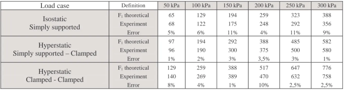
With this new value of the bending momentum and the usual formulas for the collapse load of the two kinds of isostatic and hyperstatic bending on a tube, we have now a very good correlation between experimental and theoretical results for collapse loads as shown in Table 3.
Table 3: Collapse load on tube with various boundary conditions
Load case Definition 50 kPa 100 kPa 150 kPa 200 kPa 250 kPa 300 kPa
Isostatic Simply supported F1 theoretical Experiment Error 65 68 5% 129 122 6% 194 175 11% 259 248 4% 323 292 11% 388 356 9% Hyperstatic
Simply supported – Clamped
F1 theoretical Experiment Error 97 96 1% 194 190 2% 292 300 3% 388 375 3,5% 485 500 3% 582 580 1% Hyperstatic Clamped - Clamped F1 theoretical Experiment Error 129 140 8% 259 269 4% 388 389 1% 517 470 10% 647 632 2,5% 776 758 2,5%
The analogy between collapse plastic analysis of beams and the theoretical results obtained on collapse loads of inflatable beams compared to experimental results proves that one can use the usual “plastic” theory to compute collapse loads for inflatable beams at high pressure. It is well known that the two theorems of collapse analysis lead to optimisation problems which can be easily solved nowadays5. We can therefore use all these results to compute collapse loads of complex structures made of inflatable beams.
DEFLECTIONS
Let’s now consider the results on the deflections. Main & all have compared experimental values of the deflections of inflatable cantilever tubes with those given by a usual Bernoulli beam theory3. Their results are strong in the scale of applied loads and pressure, and also for the kind of material with low constitutive law used for their experiments. When the inflation pressure is increased, geometrical stiffness and following forces must be taken into account in the theoretical solution giving the values of the deflections
for this kind of beams. The obvious reason is that in a usual beam theory, the values of the deflections depend only on the flexural rigidity of the beam.
The pressure doesn’t appear in the usual beam solution, and it seems clear that an inflated fabric beam at an extremely low pressure has very large deflections. We have tried to apply a yarn theory to our inflatable beams, and in this case the result is in reverse order: the deflection values are close to experimental ones when the pressure is low, but go far from reality at high pressure4. Moreover in a yarn theory deflections are independent of the material constitutive law and this is irregular. We will show that in fact the deflections of inflatable structures are a linear set of yarn and beam deflections.
Let’s come back on the main results of Reference6.
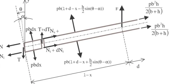
Equilibrium equations are written in the deformed state of the beam to take into account the geometrical stiffness and the following forces, and a Timoshenko’s beam theory is used because sections of the beams don’t satisfy to the usual Bernoulli beam theory.
The pressure effects are supposed to be replaced by forces normally applied to the membranes, because they
7 are in fact following forces. The angle between the membranes and the horizontal axis is named θ. Ni and
Ns denote the resultant stress respectively in the lower and upper membrane. T is the shearing stress.
y
θ
α
N
N
i(
b
h
)
2
h
pb
2+
F )) sin( 2 h x d ( pbl+ − − θ−αh
)) sin( 2 h x d ( pbl+ − + θ−α x − ld
T
N
i+ dN
iN
s+
dN
ST+dT
(
)
h
b
2
h
pb
2+
pbdx
pbdx
Figure 7. Loads on an inflatable panel element
Equilibrium equations imply:
h b h b p N N 2 i s + = + (11)
( )
θ−α − =F pbh T (12)( ) (
N N)
0 2 h x Fl− + S− i= (13)For these inflatable panels, the shear stress can be neglected with respect to the influence of the normal
stress6. The stresses in the membranes are:
( ) ( ) ( )
x h F h b 2 h b p x N 2 i − − + = l (14)( ) ( ) ( )
x h F h b 2 h b p x N 2 s + − + = l (15)Experiments have shown that the panel behave like a Timoshenko beam: if P is a point of the neutral fibre and if Q is a point of the lower or the upper membranes, the displacements are given by the following relations:
( )
P u(x)ex v(x)eyu = + (16)
( ) ( )
Q uP PQu = +Ω∧ with Ω=αez (17)
The horizontal displacement u(x) and the deflection v(x) are only functions of x. The local strains εi
( )
x and( )
xs
ε in the two membranes are therefore:
( )
,x ,x i 2 h u x= + α ε (18)( )
,x ,x s 2 h u x= − α ε (19)Resultant stresses are obtained from the constitutive law of the fabric and are given by:
( ) ( )
,x 2 bh * E h b 2 h b p x N 2 i + α + = (20) and( ) ( )
,x 2bh * E h b 2 h b p x N 2 s − α + = (21)where E* is the membrane modulus (product of the Young modulus E by the thickness e of the fabric). The comparison between formulas (14), (15) and (16) gives:
( )
x h b E F 2 dx d 2 * − = α l (22)The boundary conditions at the clamped end give the closed form of the deflection, where
I
*is equal to the second moment of area divided by the thickness:( )
= + = + x2 x6 I E F x pbh F 6 x 2 x h b E F 2 x pbh F x v * 2 l 2 3 ** l 2 3 (23) This is nothing but the sum between the tight yarn and the beam deflections. In an other word, the compliance of the inflatable panel is the sum of the yarn compliance and of the beam compliance.Figure 8 shows comparisons between theoretical and experimental results for a simply supported panel. Other
results can be found in Reference6.
-0,1 -0,075 -0,05 -0,025 0 0 0,4 0,8 1,2 1,6
Abscissae of the panel (m)
D e fl e c ti o n ( m ) 300 kPa - 165 N Theor. 300 kPa - 165 N Exp. 50 kPa - 27 N Theor. 50 kPa - 27 N Exp.
Figure 8. theoretical and experimental deflections for a simply supported panel
In the case of cantilever or simply supported tubes, the analytical solution is more complex to be established because the shearing stress can’t be neglected. The first
results are displayed in 7 and an example is given
Figure 9. -0,09 -0,06 -0,03 0 0 0,5 1 1,5 2
Abscissae of the tube (m)
D e fl e c ti o n ( m ) 100 kPa - 150 N Exp. 100 kPa - 200 N Theor. 300 kPa - 350 N Exp. 300 kPa - 350 N Theor.
Figure 9. Theoretical and experimental deflections for a simply supported tube
AN INFLATABLE FABRIC PANEL FINITE ELEMENT
Analytical results on the deflections are only relative to isostatic inflatable beams. This section of the paper is devoted to construct an inflatable beam finite element able to give good values of the displacement field for hyperstatic beams and also for structures made of inflatable beams. Let’s begin by establishing the
compliance matrix of a cantilever-inflated beam8. V and
F denote the total displacement and load vectors:
[
1 1 2 2]
T v v
V= α α ; FT=
[
F1Γ1F2Γ2]
(24)The definition of nodal unknowns is usual: vi and αi denote displacement and rotation at node i, and Fi and
Γi denote load and torque at the same node. When this
beam is a cantilever inflatable beam submitted to a load F2 and a torque Γ2 at node 2, it’s flexibility matrix ξ is simply obtained by adding the usual matrixes of beam and yarn:
[ ]
Γ + = Γ ξ = α 2 2 * * * * 2 ** 2 * * 3 2 2 2 2 F I E I E 2 I E 2 S p I E 3 F v l l l l l (25)The usual theory of the force finite element method shows that the stiffness matrix K of the free finite displacement element is obtained from the stiffness matrix of the reduced isostatic finite element Kr (the
inverse of the flexibility matrix ξ) by using the
following equations: T rB K B K= ; 1 r K=ξ− (26)
where B is the equilibrium matrix. The free stiffness matrix of the inflatable fabric beam element is therefore8:
(
)
+ + + = pS I E 3 I E 2 pS -I E 6 I E 2 I E 2 I E I E 2 I E pS -I E 6 I E 2 pS I E 3 I E 2 I E 2 I E I E 2 I E pS I E 12 pS I E 12 K * * 3 * * 2 * * 3 * * 2 * * 2 * * * * 2 * * * * 3 * * 2 * * 3 * * 2 * * 2 * * * * 2 * * 2 * * 2 2 * 2 * l l l l l l l l l l l l l l l l l l l l l l (27)9 One can notice that this stiffness matrix depends on the internal pressure of the inflatable beam. This new element is then implemented in a finite element software. After solving the displacement problem, the resultants stresses in the membranes are calculated by formulas (20 and (21). A comparison between finite element and experimental results is shown figure 10 for a clamped – clamped panel. One can see a very good agreement between the two solutions.
-0,06 -0,04 -0,02 0
0 0,4 0,8 1,2 1,6
Abscissae of the panel (m)
D e fl e c ti o n ( m
) 300 kPa - 250 N Theor.300 kPa - 250 N Exp. 50 kPa - 57 N Theor. 50 kPa - 57 N Exp.
Figure 10. Finite element and experimental deflection for a clamped – clamped panel A tube finite element has also be developed, but the final solution requires special developments because the flexibility matrix of the cantilever beam isn’t symmetric and leads to a non symmetric final finite element. Results on the deflections of hyperstatic tubes can be
found in Reference7.
BUCKLING OF INFLATABLE FABRIC PANELS
The last section relates to the buckling of inflatable beams. No relevant References have been found on buckling of inflatable structures. The first theoretical developments look promising. In the meantime, some experiments have been conducted on the inflatable panel which has been used for the previous bending studies. The influence of two parameters has been analyzed: the pressure and the free length of a clamped – clamped panel.
Theoretical analysis of the clamped-clamped panel is done by the finite element method. The panel is discretized into two finite elements. We suppose that the global stiffness matrix is given by adding the matrix of our inflatable finite element to the usual matrix of
bucking problems9: − − − − − − − = 2 2 2 2 f 4 3 3 3 36 3 36 3 4 3 3 36 3 36 30F K l l l l l l l l l l l l l (28)
The first buckling load for the panel is solution of the following equation: 0 ) K K det( + f = (29)
Where K and Kf are the reduced assembled matrixes of
the panel discretized into two finite elements. The first buckling load is finally given by:
l2 * * * * pbh I E 48 pbh I E 40 F + = (30)
The experiments have been run on a clamped-clamped panel with a free length of 1 meter. The pressure of inflation has been increased from 0 to 300 kPa by steps of 50kPa. Then the maximum load has been measured. The failure criteria is again a wrinkling of one side of the panel which leads to a complete bending shape. The Figure 11 shows the evolution of the maximum load versus pressure.
0 1000 2000 3000
0,E+00 1,E+02 2,E+02 3,E+02 Pressure (kPa) B u c k lin g l o a d ( N ) Experiment Theory
Figure 11. Evolution of the strength of a
clamped-clamped inflated panel under pure
compression.
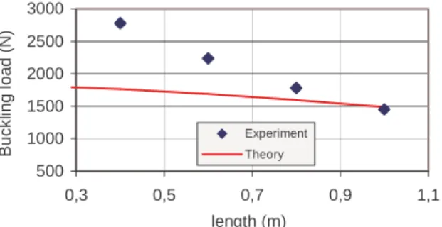
The comparison between experimental and theoretical results are satisfactory especially for high pressures. The Figure 12 below shows the influence of the free length on the buckling load. The slope of experimental response and the one of theoretical are not corresponding, but the average remains the same.
500 1000 1500 2000 2500 3000 0,3 0,5 0,7 0,9 1,1 length (m) B u c k lin g l o a d ( N ) Experiment Theory
Figure 12. Influence of the free length of a clamped-clamped inflatable panel on the buckling load.
CONCLUSION
Development of new types of structures making full use of performance characteristics of modern textile materials is now possible because theory of their behavior is available when the pressure reaches several hundreds of kPa. It’s useful to use modern textile materials with high mechanical characteristics for imagining the apprehension of inflatable beams at high pressure. The paper deals with the first experimental and analytical results on the modeling of the behavior of inflatable fabric beams. The main results are relative to the collapse loads and the deflections under bending loads. Equilibrium equations are written in the deformed state to take into account the geometrical stiffness and the following forces. A Timoshenko’s beam theory must be used because sections of the panels don’t satisfy to the usual Bernoulli beam theory. Collapse loads are obtained from equilibrium equations. Inflatable beams cannot be viewed as ordinary beams, because their deformation pattern is a set of tensioned yarn and beam behavior. A new inflatable panel theory has been developed and comparisons between experimental and theoretical results prove the accuracy of this theory on the mechanical strength of inflatable panels at high pressure. Results on the deflections of inflatable tubes can be found in Reference7. The first results on the buckling loads of inflatable panels are also displayed. Development of new types of structures making full use of performance characteristics of modern textile materials is possible because that theory of their behavior is now available when the pressure reaches several hundreds of kPa. It is also possible to foresee the building of light, easily transportable and extremely strong fabric structures. One has now also to work on the reliability of such structures in order to prove that they can be used by industry
REFERENCES
[1] Wielgosz, C., Leflaive, E., Dubé, J.F., Thomas, J. C. Behaviour of inflated fabric beams at medium pressures. Proceedings of the Twelve International Conference on Composite Material. I.C.C.M. 12, 1999, paper 334.
[2] Comer, R. L., Levy, S., “Deflections of an inflated circular cylindrical cantilever beam”, A.I.A.A. Journal, 1963, Vol. 1, N° 7, pp 1652-1655.
[3] Main, A., Peterson, S. W., Strauss, A. M., “Load - deflection behaviour of space - based inflatable fabric beams”, Journal of Aerospace Engineering, 1994, Vol. 7, N° 2, pp 225-238.
[4] Wielgosz, C., Leflaive, E., Dubé, J.F. Experimental study and numerical modelling of inflated fabric panels. In: S.V. Hoa, W. P. De Wilde, W. R. Blain, Editors, Computer Methods in Composite Materials VI. Computational Mechanics Publications, 1998. p. 137-145.
[5] Wielgosz, C. Cours et exercices de résistance des matériaux. Elasticité, plasticité, éléments finis, Editions Ellipses – Marketing SA, Paris, 2000
[6] Wielgosz, C., Thomas, J. C. Deflections of inflated fabric beams at high pressures. Thin Walled Structures, 2002, to appear.
[7] Thomas, J. C., Etude expérimentale et modélisations analytique et numérique de poutres gonflables à haute pression, Thèse de doctorat, Université de Nantes, janvier 2002.
[8] Wielgosz, C., Thomas, J. C. An inflatable fabric beam finite element. Communications in Numerical Methods in Engineering, 2002, submitted
[9] S. Dubigeon, Mécanique des milieux continus, Techniques et Documentation, Lavoisier, Paris, 1986