Science Arts & Métiers (SAM)
is an open access repository that collects the work of Arts et Métiers Institute of Technology researchers and makes it freely available over the web where possible.
This is an author-deposited version published in: https://sam.ensam.eu Handle ID: .http://hdl.handle.net/10985/18377
To cite this version :
Mathilde GAUME, Sylvain PERSOHN, Claudio VERGARI, Christophe GLORION, Wafa SKALLI, Lotfi MILADI - Biomechanical cadaver study of proximal fixation in a minimally invasive bipolar construct - Spine Deformity - Vol. 8, n°1, p.33-38 - 2020
Any correspondence concerning this service should be sent to the repository Administrator : [email protected]
Biomechanical cadaver study of proximal fixation in a minimally
invasive bipolar construct
M. Gaume1,2 · S. Persohn1 · C. Vergari1 · C. Glorion2 · W. Skalli1 · L. Miladi2
Study design Biomechanical human cadaver study.
Objective To determine the three-dimensional intervertebral ranges of motion (ROMs) of intact and hook-instrumented tho-racic spine specimens subjected to physiological loads, using an in vitro experimental protocol with EOS biplane radiography.
Summary of background data Pedicle screws are commonly used in thoracic instrumentation constructs, and their biome-chanical properties have been widely studied. Promising clinical results have been reported using a T1–T5 thoracic hook–claw construct for proximal rod anchoring. Instrumentation stability is a crucial factor in minimizing mechanical complications rates but had not been assessed for this construct in a biomechanical study.
Methods Six fresh-frozen human cadaver C6–T7 thoracic spines were studied. The first thoracic vertebrae were instrumented using two claws of supra-laminar and pedicle hooks, each fixed on two adjacent vertebrae, on either side of a single free vertebra. Quasi-static pure-moment loads up to 5 Nm were applied to each specimen before and after instrumentation, in flexion–extension, right and left bending, and axial rotation. Five steel beads impacted in each vertebra allowed 3D tracking of vertebral movements on EOS biplanar radiographs acquired after each loading step. The relative ranges of motion (ROMs) of each pair of vertebras were computed.
Results Mean ROMs with the intact specimens were 17° in flexion–extension, 27.9° in lateral bending, and 29.5° in axial rotation. Corresponding values with the instrumented specimens were 0.9°, 2.6°, and 7.3°, respectively. Instrumentation sig-nificantly (P < 0.05) decreased flexion–extension (by 92–98%), lateral bending (by 87–96%), and axial rotation (by 68–84%).
Conclusion This study establishes the biomechanical stability of a double claw–hook construct in the upper thoracic spine, which may well explain the low mechanical complication rate in previous clinical studies.
Level of evidence Not applicable, experimental cadaver study.
Keywords Thoracic fixation · Biomechanical cadaver study · Neuromuscular scoliosis · Minimally invasive surgery · Bipolar construct
Introduction
Spinal deformities can affect a large spectrum of the popu-lation, from young children suffering from idiopathic or neuromuscular scoliosis, to aging adults who can develop degenerative scoliosis. These deformities often have a
negative impact on the patient’s quality of life and, in the most severe cases, on their function. For those cases which do not respond to conservative treatment, spinal fusion is the most usual intervention, which aims at correcting the deformity while preserving the patient’s balance.
Pedicle screws are commonly used in instrumentation constructs to fuse the thoracic spine. However, this approach requires time-consuming open surgeries. An innovative surgical technique for treating adults and children spi-nal deformity with fusionless bipolar constructs has been recently developed with promising clinical results [1, 2]. This technique involves a bilateral fixation of two sub-fascial inserted rods on the proximal thoracic vertebrae achieved by two claws, each consisting of supra-laminar and pedi-cle hooks fixed on two adjacent vertebrae. The two claws
* M. Gaume
1 Arts et Métiers ParisTech, LBM/Institut de Biomécanique
Humaine Georges Charpak, 151 Bd. de l’Hôpital, 75013 Paris, France
2 Pediatrics Orthopedics Department, Necker Hospital, Paris
Descartes University, Assistance Publique Hôpitaux de Paris, Paris, France
are separated by a single free vertebra. Distal bilateral fixa-tion is ensured by ilio-sacral screws. The construct can be implanted not only with an open surgery, but also with a minimally invasive approach.
While the biomechanical behavior of constructs using pedicle screws has been assessed extensively by in vitro studies, these often focused on the lower thoracic spine [3,
4]. To our knowledge, no study has evaluated the mechanical behavior of bipolar anchoring constructs with claw–hooks in the upper thoracic spine [5]. The low rate of mechanical complications in the previous clinical studies using thoracic double claw–hook invited a biomechanical study to deter-mine whether strong thoracic construct stiffness might be a contributing factor.
Our objective here was, therefore, to determine the three-dimensional intervertebral range of motion (ROM) of cadaver thoracic-spine specimens subjected to physiologi-cal loads before and after instrumentation with our double claw–hook technique. To this end, we developed an in vitro experimental protocol involving EOS biplane radiographic imaging for motion tracking. We focused on construct stiff-ness given the importance of this characteristic to maintain scoliotic curve correction over time and decrease the risk of mechanical complications.
Materials and methods
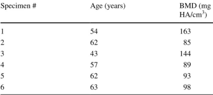
Specimen preparationA total of 6 fresh-frozen human male cadaver C6–T7 spines were studied. Median age at death was 57 years (range 43–63 years) (Table 1). After harvesting, the specimens were immediately sealed in double-thickness plastic bags and stored at − 20 °C until testing. Computed tomography (CT) screening was performed to rule out spinal deformi-ties or diseases and to allow 3D bone reconstruction using the segmentation technique (Medical imaging interaction toolkit. MITK 2016.11, http://mitk.org/wiki/Downl oads). Bone mineral density was determined by phantom-calibrated CT scanning. Then, each specimen was thoroughly cleaned of all soft tissue while preserving the disk, facet joint cap-sules, and ligaments. Irrigation with 0.9% sodium chloride solution was used to keep the specimens moist throughout preparation and testing.
Instrumentation
The thoracic double claw–hook technique includes 2 large blade supra-laminar hooks, 2 progressive reduced blade supra laminar hooks, 4 pedicle hooks, 2 titanium rods (5.5 mm) and 2 cross-links. The first thoracic vertebras were instrumented bilaterally using a double claw. Each claw
consisted of supra-laminar and pedicle hooks fixed on two adjacent vertebras (T1–T2 and T4–T5), and the two claws were separated by a single free vertebra (T3). The sub-lam-inar hook was first affixed to the hook pusher with the cap and was then inserted between the ligamentum flavum and the lamina, without opening the spinal canal. The pedicle hooks were also affixed to the hook pusher, inserted manu-ally under the articular facet, then gently impacted using a hammer, without removing any bone. The rod system was composed of two long pre-curved titanium rods (diameter 5.5 mm) connected by a transverse connector at the level of T3 and T6. All six cadaver specimens were instrumented by the same senior spinal surgeon and spinal surgery fellow.
Biomechanical testing
Figure 1 depicts the setup used for biomechanical testing. The proximal and distal ends of each specimen were pot-ted in 3D prinpot-ted blocks, which were custom-made based on vertebral CT-scan reconstructions. Three screws were added to each posterior arch to ensure strong fixation to the testing apparatus.
Quasi-static pure-moment loads were applied to C6 in increments of 1 Nm, up to a maximum of 5 Nm, in the fol-lowing sequence: flexion and extension, right and left bend-ing, and axial rotation. Loads were measured with a 6-axis load cell (FTD-Gamma SI-130-10, ATI Industrial Automa-tion, Apex, NC). Three loading cycles were first performed in each direction as preconditioning to minimize viscoelastic effects. The measurements were performed during the fourth cycle.
Testing took place within an EOS system (EOS imag-ing, Paris, France). A biplanar radiograph of the specimen was acquired after each loading increment, before and after instrumentation. All vertebras were reconstructed in 3D. Five steel beads each 2 mm in diameter were impacted into each vertebra from C7 to T6 (4 in the body and 1 in the spinous process) to allow 3D motion tracking on the biplane radiographs (Figs. 2, 3). The relative ranges of motion
Table 1 Age of the thoracic specimen donors and bone mineral den-sity of each specimen; all donors were male
BMD bone mineral density, HA hydroxyapatite
Specimen # Age (years) BMD (mg
HA/cm3) 1 54 163 2 62 85 3 43 144 4 57 89 5 62 93 6 63 98
Spine Deformity
(ROMs) of each pair of vertebras were computed in the sag-ittal plane for flexion–extension, coronal plane for lateral bending, and axial plane for rotation. Relative ROM between the intact specimens and constructs was defined as follows: relative ROM (%) = 100% × [(ROM construct − ROM intact)/ ROM intact].
Statistical analysis
Relative ROMs between T1 and T5 at the maximum load of 5 Nm were described as median and percentages. P values smaller than 0.05 were taken to indicate significant differ-ences. The statistical analysis was performed using Excel (Microsoft, Redmond, WA).
Results
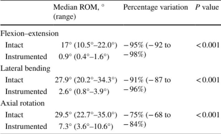
No fixation failures occurred during testing. Table 2 lists mean ROMs of T1 relative to T5 at maximal loading for the intact and instrumented specimens. ROMs with the intact specimens were largest with loading in lateral bending and axial rotation. After instrumentation, all ROMs were signifi-cantly reduced, by 92–98% in flexion–extension, 87–96% in lateral bending, and 68–84% in axial rotation (Figs. 4,
5, 6, 7).
Discussion
This in vitro study examined the stiffness of the T1–T5 tho-racic double claw–hook construct used for proximal anchor-ing, a scoliosis-correction procedure that was designed for adults and pediatric patients and has produced promising clinical outcomes. We focused on construct stiffness, which plays a key role in maintaining scoliosis correction over time. Compared to the intact specimens, the instrumented specimens had significantly smaller ROMs in all three direc-tions, although the decrease in axial rotation was less marked than the decreases in flexion–extension and lateral bending. The results were consistent across specimens.
The double claw consisting of two sets of supra-laminar and pedicle hooks, each fixed on two adjacent vertebrae, and separated by a single free vertebra, may make a key contribution to construct stiffness, while also minimizing the damage to the adjacent-segment facet capsules. The two transverse connectors also contribute to provide stiffness. In a biomechanical cadaver assessment of a long thoracic construct with pedicle screws, adding transverse connectors further decreased rotational ROM [6]. Another biomechani-cal cadaver study focused on the thoracolumbar spine and found that adding two transverse connectors to a pedicle screw construct increased both rotational and lateral-bend-ing stiffness [7]. In our study, the smaller decrease in axial rotation after instrumentation compared to the decreases in
Fig. 1 Specimen potted at C6 and T7 before (left) and after (right) instrumentation
Fig. 2 Specimen mounted on the specially designed testing apparatus equipped with an EOS imaging system for motion tracking
flexion–extension and lateral-bending may be attributable to the parallel orientation of the rods, resulting in the construct behaving as a rectangular frame, and therefore being less stiff in axial rotation than in the other two directions.
Pure-moment loads were applied to the specimens, which may generate simpler loading conditions compared to those occurring in physiological situations. The maximum load of 5 Nm was a compromise between the maximum loads in previous cadaver studies of the cervical spine (approxi-mately 1–2 Nm) [8, 9] and lower thoracic spine (approxi-mately 4–8 Nm). We measured the ROM values without the rib cage, in keeping with most previously published stud-ies [10], to focus on the stiffness provided by the construct itself. The rib cage increases the stiffness of the thoracic spine in all loading directions [11], and ROMs with the rib cage would, therefore, have been smaller than those meas-ured in our study. The pure-moment loading and lack of the rib cage made the comparison between the intact and instrumented specimens more straightforward.
Previous biomechanical assessments of thoracic stiffness focused on the lower thoracic spine (T4–T12) [12]. Pedicle screws raise concern at the upper thoracic spine given the risk of iatrogenic neurologic injury and the smaller size of the thoracic pedicles. One biomechanical study compared load at failure between pedicle screws and transverse pro-cess screws in T1–T4 [13]. No published studies similar to ours are available for comparison with our findings. In vivo studies of thoracic spine motion (T1–T12) showed wide ranges, of 31.2°–75° in lateral bending [14] 41.8°–95.5° in axial rotation [15, 16] and 25.6°–71° in flexion–extension [17–19]. Although this wide variability might appear as an obstacle to the interpretation of biomechanical studies, the
Fig. 3 Example of biplanar EOD images of a specimen; note the five steel beds impacted in each vertebra to allow motion tracking
Table 2 Mean displacement of T1 relative to T5 during 5 Nm loading before and after instrumentation
Median ROM, °
(range) Percentage variation P value Flexion–extension Intact 17° (10.5°–22.0°) − 95% (− 92 to − 98%) < 0.001 Instrumented 0.9° (0.4°–1.6°) Lateral bending Intact 27.9° (20.2°–34.3°) − 91% (− 87 to −96%) < 0.001 Instrumented 2.6° (0.8°–3.9°) Axial rotation Intact 29.5° (22.7°–35.0°) − 75% (− 68 to −84%) < 0.001 Instrumented 7.3° (3.6°–10.6°)
Fig. 4 Effect of loading to 5 Nm on flexion–extension before (left) and after (right) instrumentation
very small residual ROMs after instrumentation in our study indicate excellent stiffness of the construct.
Our work is the first in vitro biomechanical study using the EOS system instead of optoelectronic or ultrasound systems to measure 3D intervertebral thoracic ROM [20]. EOS imaging was used to track the movements of the five steel beads impacted in each vertebra from C7 to T6. Unlike external optical markers, beads do not occupy space around the sample and are therefore easier to implant. The accu-racy of biplanar radiography to determine vertebral motion was recently assessed on the lower cervical spine [21]. A 95% confidence interval of 0.02° was obtained on vertebral rotation. Moreover, optical markers can come into contact with each other or with the sample during large movements, whereas beads impacted within the vertebral body never
contact each other. This study has limitations. First, this con-struct has potential use in children and adult’s spine deformi-ties, but specimens from adults without scoliosis were used. Thus, caution is in order when extrapolating our findings to pediatric patients, since osseous–ligamentous complex in children is different from elderly adult spines. Second, we studied only six specimens. Many previously published stud-ies also used similarly small sample sizes, due to the lim-ited availability and high cost of human cadaver specimens. Third, all six instrumentations were performed by the same senior surgeon assisted by the same fellow. However, this methodology was chosen to limit inter-specimen variabil-ity. Fourth, no comparison was made between the proposed construct and other options for managing spinal deformity, such as a pedicle screws fixation. The use of thoracic hooks may be controversial since several in vitro biomechanical studies [22] demonstrated pedicle screws had greater pull-out strength compared to pedicle and supra-laminar hooks. However, the use of thoracic hooks in this particular con-figuration of double claws has never been described before. Long-term clinical studies and finite element analyses are being conducted to further characterize the behavior of this new construct and to compare the thoracic double claw anchor to pedicle screws. The results reported here will assist in creating finite element models and in evaluating factors potentially responsible for hook or screw pullout.
Conclusion
The data reported in this work indicate that a construct involving double hook–claw anchoring at the proximal tho-racic spine provides excellent stiffness of a bipolar instru-mentation. Further investigations are planned to evaluate distal fixation stability and strain distribution along the rods.
Fig. 5 T1–T5 flexion–extension ROM at 5 Nm
Fig. 6 T1–T5 lateral bending ROM at 5 Nm
Key points
• A thoracic double claw–hook has been used for the thoracic anchoring of a novel fusionless rod construct designed to treat children and adult’s scoliosis.
• This novel construct produced promising clinical out-comes but had not been subjected to a biomechanical assessment.
• An in vitro biomechanical study using EOS biplanar radiography to measure 3D intervertebral thoracic ranges of motion showed a high degree of stiffness in flexion– extension, lateral bending, and axial rotation.
• The marked stability of the thoracic construct may have contributed to the low mechanical complication rate in the previous clinical study.
Author contributions MG: study design, data acquisition and inter-pretation, engineering, manuscript drafting and revision for important intellectual content, approval of the version to be published. SP: study design, engineering, manuscript drafting, and approval of the final version to be published. CV: data interpretation, engineering, manu-script drafting, and approval of the final version to be published. CG: data analysis, manuscript revision for important intellectual content, and approval of the final version to be published. WS: study design, manuscript drafting, and approval of the final version to be published. LM: study design, specimen instrumentation, manuscript drafting, and approval of the final version to be published.
Funding Part of this study was financed by EUROS, including the spinal implants. We are grateful to the BiomecAM chair program on musculoskeletal modeling for financial support.
Compliance with ethical standards
Conflict of interest The author declares that they have no conflict of interest.
Ethics/IRB approval CPP n° ID-RCB/ EUDRACT: 2014-A01043-44.
References
1. Miladi L, Gaume M, Khouri N, Topouchian V, Glorion C (2018) Minimally invasive surgery for neuromuscular scoliosis: results and complications in a series of one hundred patients. Spine (Phila Pa 1976) 43:E968
2. Wolf S (2019) Correction of adult spinal deformity with a minimally invasive fusionless bipolar construct: Preliminary results. Orthop Traumatol Surg Res. https ://doi.org/10.1016/j. otsr.2019.02.015
3. Deviren V, Acaroglu E (2005) Pedicle screw fixation of the tho-racic spine: an in vitro biomechanical study on different configura-tions. Spine 30(22):2530–2537
4. Morgenstern CW, Ferguson S (2003) Posterior thoracic extrape-dicular fixation: a biomechanical study. Spine 28(16):1829–1835 5. Metzger M, Robinson S (2016) Biomechanical analysis of the proximal adjacent segment after multilevel instrumentation of the thoracic spine: do hooks ease the transition? Global Spine J 6:335–343
6. Kuklo TR, Dmitriev AE (2008) Biomechanical contribution of transverse connectors to segmental stability following long segment instrumentation with thoracic pedicle screws. Spine 33:482–487
7. Lynn G, Mukherjee DP (1997) Mechanical stability of thoraco-lumbar pedicle screw fixation. The effects of crosslinks. Spine 22:1568–2001
8. Hackenberg L, Link T (2002) Axial and tangential fixation strength of pedicle screws versus hooks in the thoracic spine in relation to bone mineral density. Spine 27:937–942
9. Laar W, Meester RJ, Smit TH, van Royen BJ (2007) A biomechan-ical analysis of the self-retaining pedicle hook device in posterior spinal fixation. Eur Spine J 16:1209–1214
10. Borbowski SL, Tamrazian E (2016) Challenging the conventional standard for thoracic spine range of motion. A systematic review. JBJS Rev 4(4):e5
11. Brasiliense LB, Lazaro BC (2011) Biomechanical contribution of the rib cage to thoracic stability. Spine 23(26):E1686–E1693 12. Baladaud L, Gallard E (2002) Biomechanical evaluation of
biped-icular spinal fixation system. A comparative stiffness tests. Spine 27(17):1875–1880
13. Heller JG, Shuster JK (1999) Pedicle and transverse process screws of the upper thoracic spine. Spine 24(7):654–658 14. Fujimori T, Iwasaki M (2014) Kinematics of the thoracic spine in
trunk lateral bending: in vivo three dimensional analysis. Spine J 14(9):1991
15. Fujimori T, Iwasaki M (2012) Kinematics of the thoracic spine in trunk rotation: in vivo 3 dimensional analysis. Spine 37(21):E1318–E1328
16. Heneghan NR, Hall A (2009) Stability and intra tester reliability of an in vivo measurement of thoracic axial rotation using an innovation methodology. Man Ther 14(4):452–455
17. Troke M, Moore AP (1998) Reliability of the OSI CA 6000 Spine Motion Analyser with new skin fixation system when used on the thoracic spine. Man Ther 3(1):27–33
18. Mannion AF, Knecht K (2004) A new skin surface device for measuring the curvature and global and segmental ranges of motions of the spine: reliability of measurements and comparison with data reviewed from the literature. Eur Spine J 13(2):122–136 19. Morita D, Yukawa Y (2014) Range of motion of thoracic spine in
sagittal plane. Eur Spine J 23(3):673–678
20. Humbert L, De Guise JA, Aubert B, Godbout B, Skalli W (2009) 3D reconstruction of the spine from biplanar X-rays using para-metric models based on transversal and longitudinal inferences. Med Eng Phys 31(6):681–687
21. Muth-seng C, Brauge D, Soriau N, Sandoz B, Van den Abbeele M, Skalli W, Laporte S (2019) Experimental analysis of the lower cervical spine in flexion with a focus on facet tracking. J Biomech.
https ://doi.org/10.1016/j.jbiom ech.2019.06.022
22. Liljenqvist U, Hackenberg L, Link T, Halm H (2001) Pullout strength of pedicle screws versus pedicle and laminar hooks in the thoracic spine. Acta Orthop Belg 67:157–163