Science Arts & Métiers (SAM)
is an open access repository that collects the work of Arts et Métiers Institute of
Technology researchers and makes it freely available over the web where possible.
This is an author-deposited version published in: https://sam.ensam.eu Handle ID: .http://hdl.handle.net/10985/15936
To cite this version :
Taoufik QORIA, Chuanyue LI, Ko OUE, François GRUSON, Frédéric COLAS, Xavier GUILLAUD, Thibault PREVOST Tuning of AC voltagecontrolled VSC based Linear Quadratic Regulation -In: IEEE PES PowerTech 2019, Italie, 2019-06-23 - n/a - 2019
Any correspondence concerning this service should be sent to the repository Administrator : archiveouverte@ensam.eu
Tuning of AC voltage-controlled VSC based Linear
Quadratic Regulation
Taoufik Qoria, Chuanyue Li, Ko Oue, François Gruson,
Frederic Colas, Xavier
.
Guillaud
Univ. Lille, Centrale Lille, Arts et Métiers Paris Tech, HEI, EA 2697 - L2EP - Laboratoire d’Electrotechnique de
Puissance, F-59000 Lille, France Taoufik.qoria@ensam.eu
Thibault Prévost
PES - Direction de la R&D et de l'innovation - Expertise Réseau de Transport d’Electricité,
Versailles, France
Abstract— In the near future, power converters will be
massively introduced in transmission grids due to renewable energy sources and high voltage direct current (HVDC) increase. Voltage Source Converter (VSC) control laws assume that Synchronous Generators (SGs) build a stiff AC voltage which allows the synchronization of converters. This is one of the major reasons that limit the high integration of current-source converters in transmission grid. This constraint is no longer relevant when power converters operate as a voltage source based on the grid-forming concept. This concept uses an inner cascaded PI controllers in order to regulate the output AC voltage. However, it is difficult to tune its controller parameters for stable operation in grid-connected mode. This paper proposes an alternative state-feedback control with integral compensator based linear quadratic regulation (LQR) in order to ensure a stable operation and to get a better AC voltage transient and good decoupling between reactive and active power. The proposed control will be fully analyzed and compared to conventional methods.
Index Terms-- Power transmission System, 2-Level Voltage
Source Converter, Grid-forming control, Linear Quadratic Regulator, Small-signal analysis, Active power and AC voltage transient coupling.
I. INTRODUCTION
For environmental reasons, the demand of electrical energy produced by distributed and renewable-energy sources, such as wind and solar is increasing. Since more and more renewable energy production systems and HVDC systems are interfaced to alternative grids through power converters, these applications lead to the increase of power electronic devices in the grid. Thus, some control modifications are required. In this context, the MIGRATE project [1], [2] is interested in the massive integration of power electronics devices in transmission grids, highlight future challenges and propose new technical solutions.
Nowadays, SGs are dominating the electrical grid, establishing a stable voltage and frequency that allow VSCs
to be synchronized at the point common coupling (PCC) through the phase locked loop (PLL) and injecting the power to the grid. These converters are characterized as “grid-following” VSCs that behave as current sources. However, as the demand of these generating units is growing rapidly, some synchronous areas might occasionally be operated without synchronous machines. In such conditions, grid-following VSCs loose the synchronization [3] and become unstable, therefore, electrical power can no longer be provided to loads. Thus the current operation mode will dramatically change, while the grid stability still has to be ensured with the same level of reliability as today, or better. To operate autonomously, the control law should have to be changed. Power converters need to change from following the grid to leading the grid behavior [3]–[6]. This capability is known as “grid-forming” concepts, where power converters are able to generate an AC voltage with a given amplitude and frequency at PCC.
In a similar way to synchronous generators, each power converter must play an identical role in order to form an electrical system and perform independently, without communication with other devices, but only based on local measurements. In this context, two well-known primary controls are proposed in the literature e.g. the virtual synchronous machine (VSM) [7] and the droop control [8]. It can be demonstrated that these controls are mathematically identical [9]. They allow at once to emulate the virtual inertia of synchronous machines and to share power.
In Micro-grid and Uninterruptible Power Supply (UPS), AC voltage regulation is ensured by two PI cascaded controllers applied to grid-forming VSCs as inner loops [10]– [15]. Yet, it is difficult to tune controller gains of the cascaded PI controller because of the system modes coupling and controller’s bandwidth, this issue has been observed especially in grid-connected topology [12], [13], [15]. Some methods are proposed in the literature to tune controller gains. In [12], authors use eigenvalues parametric This project has received funding from the European Union’s Horizon
2020 research and innovation program under grant agreement No 691800. This paper reflects only the author’s views and the European Commission is not responsible for any use that may be made of the information it contains.
sensitivities to determine the controller gains. In [11], [13] authors are setting to zero the voltage feedforward terms to maintain a stable operation. Yet, the dynamic is very slow, and poorly damped. Otherwise, the author in [15] proposes another tuning method which impose stability, damping and dynamics constrains on the system poles, the gains deduced improve the voltage dynamic and has a faster response characteristic than other methods. However, the transient performances and the power coupling still need to be improved.
From another side, the design of the primary control is based on a very strong hypothesis [8] (i.e. the coupling transfer functions between active and reactive power are neglected in the control design). This implies that the dynamics of the AC voltage must vary slowly. This objective can be achieved only by tuning carefully the voltage controller, hence, if the voltage dynamic is well controlled, the power transient coupling becomes be negligible.
This paper proposes an alternative control which has a better dynamics than conventional controllers (i.e.; Fast response time, low overshoot and less coupling between active power and AC voltage). Employing the system state-space model, a feedback control with an integral compensator is developed. The control gains are designed with linear quadratic regulator (LQR), analyzed, and compared to the conventional cascaded PI control.
The LQR cost factors are tuned using root-locus and participations factors [16].
The paper is organized as follows. The Section II recalls the system modeling of the grid-forming VSC with the conventional structure of the cascaded PI controllers. In section III, the LQR is applied to the grid-forming VSC, analyzed and compared with conventional methods. Conclusions and perspectives are drawn in section IV.
II. GRID-FORMING BASED CONVENTIONAL CONTROL STRUCTURE
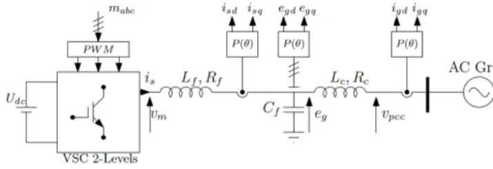
The grid-forming VSC consists of a 2-Level VSC supplied by an ideal DC voltage and connected to the AC grid through an LCL filter. This converter has to cope with various grid topologies and especially the connection to an infinite bus.
In this paper, the grid is modelled by an equivalent AC voltage source and its equivalent impedance.
An LCL filter is very often attached to both grid-feeding converter and grid-forming converter. The filter attenuates voltage distortions produced by the Pulse Width Modulation (PWM). The main difference is not the topology of the converter itself but its control since an instantaneous voltage loop is implemented in forming control where grid-feeding is mainly focused on the control of the grid current. In case of association of several grid forming converters, a droop control is added to ensure a power sharing.
A. System modeling
Following the notations in Fig. 1, state variables are respectively the VSC current i , the voltage across the filter
capacitor e and the grid current i through the transformer inductance Lc.
Figure 1. VSC 2-Level Circuit
To simplify the system study, the VSC is represented by its average model, and the state variables are represented in d − q frame. The per-unit system is used in order to absorb large differences in absolute values into base relationships. Thus, representing states in per-unit values become more uniform.
The following is the state space model of the three-phase system: x = [A]x + [B]u + [F]wy = [C]x (1) Where: x = i i e e i i = [v v ] , = [v v ], = [e e ] = −R L ω ω − ω L 0 0 0 −ωω −R L 0 − ω L 0 0 ω C 0 0 ω ω − ω C 0 0 ω C −ωω 0 0 − ω C 0 0 ω L 0 − R L ω ω 0 0 0 ω L −ω ω − R L = 0 0 0 0 0 0 0 0 0 0 = 0 0 1 0 0 0 0 0 0 1 0 0 F = 0 0 0 0 − 0 0 0 0 0 0 − (2)
The vectors x and u are the state variables and the system inputs respectively, w is the grid-voltage considered as a perturbation in this case. Outputs y are the AC voltage in d − q frame, the term of ω is the base value for the angular frequency in rad/s, corresponding to the rated frequency of the grid.
Figure 2. Cascaded-Loop based droop Control
B. Conventional control structure
The grid forming control behaves as a voltage source where the AC voltage amplitude and frequency ω∗ are
imposed. Fig. 2 shows the basic circuit diagram for a grid-forming converter which consists of cascaded-PI controllers and the primary droop control.
The primary control is a P − ω and Q − E droop control since X ≫ R in power transmission system.
The injected three phase instantaneous active and reactive power components, p and q are given by the following equations (3) and (4):
p = e i + e i (3)
q = e i − e i (4)
The low-pass filter added on the active power measurement [14] aims to avoid fast frequency variation and filter power noises:
p = p (5)
q = q (6)
where ω is the cut-off frequency.
The droop control provides references to the inner voltage loop which is responsible for AC voltage regulation across the capacitor C , likewise, the voltage loop provides current references to the inner current loop which is responsible for current control. Conventionally, controllers in cascaded structure are independently tuned by setting a lower response time for the inner current loop (i.e., fastest eigenvalues) which is limited by the first-order transfer function approximating the PWM effect [12] and higher response time for outer loops.
Based on the inner multi-loops control structure, the conventional controllers tuning method shows its effectiveness to ensure a stable operation in standalone mode, while in grid-connected topology, this method suffers from instability issues following the analysis in [15].
To deal with this issue, some tuning methods are proposed in order to ensure a stable system operation [12], [13], [15]. However, the AC voltage dynamics and the important coupling between reactive power and active power still need to be studied.
The advantage of cascaded PI controllers is the ability to obtain the current reference from the AC voltage loop so that grid-forming VSCs prevent themselves against overcurrent. However, the current loop presents the main instability origin [15]. Thus, the next section presents an alternative AC mono-loop control structure which does not require a current mono-loop regulation. The protection of the power converter based LQR control structure could be ensured using a virtual impedance [17].
III. GRID-FORMING BASED LQR
This section presents a state-feedback with an integral compensator instead of the cascaded voltage and current loops (Fig.3). The design of the control parameters is achieved thanks to a LQR method.
Thereafter, an eigenvalue analysis is presented in order to unveil the AC voltage dynamic and to improve it.
An integral compensator is enough to control the voltage across the capacitor without a steady state error in synchronous rotating frame (SRF).
Figure 3. Block diagram of inner feedback control
K and K are the state-feedback gain matrix (2 × 6) and the integral compensator matrix (2 × 2) respectively. The vector is defined as the voltage reference across capacitor from Q − E droop operation. The vector ζ is the derivative of the error between the reference and the output voltage:
r = [e∗ e∗ ] (7)
ζ = r − y = r − Cx (8)
xζ = A 0 −C 0 x ζ + B0 u + 0I r + F0 w (9) y = [C 0] xζ (10) u = −Kx + K ζ = −[K −K ] xζ (11) This controller has 16 gains in order to regulate the AC voltage and take into account the coupling between d − q axes.
In order to define the controller gains, a pole placement is feasible, however, the complexity lies on the choice of the desired poles and how do the closed loop poles influence the studied system performance. Contrary to the conventional pole placement method, the linear quadratic optimal control method provides a systematical control gain matrix K = [−K K ] based on cost factors Q and R so as to minimize the performance index J in (12).
J = (x Qx + u Ru)dt (12) Where and are a positive-definite/positive-semidefinite Hermitian matrices. In this rule, and matrices are arbitrary. The first term on the right-side of (12)
is related to the convergence speed of each state variable. The second term accounts for the expenditure of the control signals energy.
The optimum gain matrix is expressed in (13).
K = R B P (13)
where is the solution of the following RICATTI function: A P + PA + Q − PBR B P = 0 (14) The existence of the matrix implies the stability of the system.
Equation (13) implies that the selection of cost factors Q and R completely determines the optimal controller gain. One of the most common (initial) LQR tuning approaches is to consider all cost factors equally [18], i.e., R = [I] ×
and Q = [I] × . This initial parametrization will be used to
check the system stability and the AC voltage dynamics, then Q and R are adjusting in respect to the desired voltage dynamic.
A. LQR cost factors tuning
The system parameters are listed in Tab. I.
Using the initial parameterization of the cost factors (i.e.; R = [I] × Q = [I] × ) and taken into account the
droop control dynamics, the eigenvalues in Tab. II show a stable system operation.
In order to improve the system behavior, it is important to find the link between eigenvalues and the system state variables, where the interest of participation factors.
TABLE I. SYSTEM PARAMETERS
Parameter Value Parameter Value
P 1GW 1 pu cosφ 0.95 1 pu 50 Hz 31.4 rad/s 320 kV 640 kV 0.005 pu 0.15 pu 0.15 pu 0.05 pu 0.005 pu 0.02 pu 0.066 pu 1e-4 pu
TABLE II. SYSTEM EIGENVALUES = −758.65 5507.4 = −31.416 + 0
= −758.92 4879.2 = −0.36445 + 0 = −12.356 311.23 = −0.49623 + 0
= −14.652 39.50
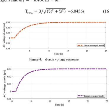
To check the AC voltage behavior, a voltage step Δe∗ = 0.03pu is applied at t=1s in both d and q axis.
The dynamics of the voltage loop is too slow with a first-order response, where T %= 8.1s in d-axis and T %= 6s in q-axis as shown in Fig. 4 and Fig. 5 respectively. T % denotes the response time.
The dynamic of the d-axis AC voltage corresponds exactly to the eigenvalue λ = −0.36445 + 0i:
T %= 3/ ( + ) =8.1682s (15)
The q-axis AC voltage dynamic corresponds exactly to the eigenvalue λ = −0.49623 + 0i:
T %= 3/ ( + ) =6.0456s (16)
Figure 4. d-axis voltage response
The participation factors for λ and λ presented in Fig. 6 reveal an important link with ζ and ζ respectively. It means that in order to improve the voltage dynamics, the cost factors Q and Q should be increased since they impact only controller’s dynamics.
Figure 6. State variables participation on λ
By varying Q and Q , it is clear from the pole map in Fig. 7 that λ and λ are getting faster; therefore Q and Q improve the AC voltage dynamics without impacting the system stability as shown in Tab. III (e.g. the variation of Q = 1e4 and Q = 1e4 yields to λ = −36.061 + 0i and λ = −31.41 + 0i which corresponds to Tr %= 85ms and
Tr %= 95ms respectively).
Figure 7. Impact of the weighting factors Q and Q on the voltage dynamic.
TABLE III. SYSTEM EIGENVALUES = −755.55 5540.7 = −42.72 + 0
= −758.97 4914 = −36.061 + 0 = −12.498 312.81 = −31.41 + 0 = −11.815 25.969
It is recalled that the coupling transfer functions between active and reactive power in the control side are neglected by considering the AC voltage amplitude as constant. Therefore, the variation of the AC voltage amplitude arouses a strong transient coupling with the active power if the AC voltage dynamics are chosen too fast.
By applying a step on the AC voltage amplitude of ΔE = 0.1pu in respect to three different response times, it is remarkable from Fig. 8 that the transient coupling between active power and AC voltage becomes more important when the rise time of the AC voltage decreases.
Figure 8. The impact of the AC voltage dynamics on the active power
B. Comparison with conventional methods
In order to show the relevance of the developed control, the comparison will be checked by applying the same event in Fig.8.
The chosen cost factors are respectively R = 1; Q = 1, and Q = 1500 which corresponds to a 200ms response time. Based on the defined cost factors, the controller gains are listed in the following Table.
TABLE IV. CONTROLLER GAINS
= 0.7242 = −1.3087 − 15 = −1.3087 − 15 = 0.7242 = 1.0269 = 0.0012034 = −0.0012034 = 1.0269 = −0.72758 = −0.00040997 = 0.00040997 = −0.72758 = −38.622 = −2.8906 = 2.8906 = −38.622
The proposed method is compared to the developed methods in [13] and [15] respectively; the compared quantities are respectively the AC voltage, the active power and the reactive power.
The results obtained in Fig. 9 clearly show the improvement brought by the proposed control. It illustrates its effectiveness in ensuring a stable operation and improving the
dynamic performances of the system comparing to what have been achieved using cascaded controllers (i.e. Fast response without overshoot). From another side, the proposed controller design presents a very small transient coupling effect between the active and reactive power contrary to the other methods.
Figure 9. The proposed control performances comparing to the conventional ones.
IV. CONCLUSION
This paper presents a state-feedback control with the integral compensator and applies the linear quadratic regulation in order to obtain optimal controller gains. The LQR approach is recalled and applied to the Grid-forming VSC, this latter is analyzed in order to achieve better performances comparing to conventional methods. Simulation results indicate that the LQR allows getting a fast AC voltage response time without overshoot and less transient coupling between active and reactive power. The main challenge of this control technique is the difficulty to limit current transients since no current loop is implemented.
REFERENCES
[1] “H2020 Migrate.” https://www.h2020-migrate.eu/.
[2] “WP3 - Control and Operation of a Grid with 100% Converter-Based Devices.” https://www.h2020-migrate.eu/.
[3] I. Erlich et al., “New Control of Wind Turbines Ensuring Stable and Secure Operation Following Islanding of Wind Farms,” IEEE Trans. Energy Convers., vol. 32, no. 3, pp. 1263–1271, Sep. 2017.
[4] G. Denis, T. Prevost, M. Debry, F. Xavier, X. Guillaud, and A. Menze, “The Migrate project: the challenges of operating a transmission grid with only inverter-based generation. A grid-forming control improvement with transient current-limiting control,” IET Renew. Power Gener., vol. 12, no. 5, pp. 523–529, 2018.
[5] I. Erlich, “Control Challenges in Power Systems Dominated by Converter Interfaced Generation and Transmission Technologies,” in NEIS 2017; Conference on Sustainable Energy Supply and Energy Storage Systems, 2017, pp. 1–8.
[6] J. Rocabert, A. Luna, F. Blaabjerg, and P. Rodríguez, “Control of Power Converters in AC Microgrids,” IEEE Trans. Power Electron., vol. 27, no. 11, pp. 4734–4749, Nov. 2012.
[7] H. Beck and R. Hesse, “Virtual synchronous machine,” in 2007 9th International Conference on Electrical Power Quality and Utilisation, 2007, pp. 1–6.
[8] L. Zhang, L. Harnefors, and H. Nee, “Power-Synchronization Control of Grid-Connected Voltage-Source Converters,” IEEE Trans. Power Syst., vol. 25, no. 2, pp. 809–820, May 2010.
[9] T. QORIA, F. GRUSON, F. COLAS, G. Denis, T. PREVOST, and G. Xavier, “Inertia effect and load sharing capability of grid forming converters connected to a transmission grid,” The 15th IET international conference on AC and DC Power Transmission, UK, p. 6, Jan-2019.
[10] Y. Du, J. M. Guerrero, L. Chang, J. Su, and M. Mao, “Modeling, analysis, and design of a frequency-droop-based virtual synchronous generator for microgrid applications,” in 2013 IEEE ECCE Asia Downunder, 2013, pp. 643–649.
[11] F. Salha, “Microréseaux îlotables: étude et coordination des protections des générateurs et du réseau,” p. 198.
[12] S. D’Arco, J. A. Suul, and O. B. Fosso, “Automatic Tuning of Cascaded Controllers for Power Converters Using Eigenvalue Parametric Sensitivities,” IEEE Trans. Ind. Appl., vol. 51, no. 2, pp. 1743–1753, Mar. 2015.
[13] G. Denis, T. Prevost, P. Panciatici, X. Kestelyn, F. Colas, and X. Guillaud, “Improving robustness against grid stiffness, with internal control of an AC voltage-controlled VSC.,” in 2016 IEEE Power and Energy Society General Meeting (PESGM), 2016, pp. 1–5.
[14] Y. A. I. Mohamed and E. F. El-Saadany, “Adaptive Decentralized Droop Controller to Preserve Power Sharing Stability of Paralleled Inverters in Distributed Generation Microgrids,” IEEE Trans. Power Electron., vol. 23, no. 6, pp. 2806–2816, Nov. 2008.
[15] T. Qoria, F. Gruson, F. Colas, X. Guillaud, M. Debry, and T. Prevost, “Tuning of Cascaded Controllers for Robust Grid-Forming Voltage Source Converter,” in 2018 Power Systems Computation Conference (PSCC), 2018, pp. 1–7.
[16] S. Danielsen, O. B. Fosso, and T. Toftevaag, “Use of participation factors and parameter sensitivities in study and improvement of low-frequency stability between electrical rail vehicle and power supply,” in 2009 13th European Conference on Power Electronics and Applications, 2009, pp. 1–10.
[17] A. D. Paquette and D. M. Divan, “Virtual Impedance Current Limiting for Inverters in Microgrids With Synchronous Generators,” IEEE Trans. Ind. Appl., vol. 51, no. 2, pp. 1630–1638, Mar. 2015. [18] “Design and Implementation: Linear Quadratic Regulator
(Paperback) par Chandrapati Sirisha: LAP Lambert Academic Publishing 9783846556436 Paperback, Aufl.. - The Book Depository EURO.” 0.8 1 1.2 1.4 1.6 1.8 2 Time [s] 1 1.05 1.1 1.15 1.2 A C vo lt age A m pl it ud e [p u] Proposed Control Control Tuning in [13] Control Tuning in [11] 0.8 1 1.2 1.4 1.6 1.8 2 Time [s] 0 0.2 0.4 0.6 0.8 1 R eac ti ve P ow er [p u] Proposed Control Control Tuning in [13] Control Tuning in [11] 0.8 1 1.2 1.4 1.6 1.8 2 Time [s] 0.2 0.4 0.6 0.8 1 A cti ve P ow er [p
u] Proposed ControlControl Tuning in [13] Control Tuning in [11]