O
pen
A
rchive
T
OULOUSE
A
rchive
O
uverte (
OATAO
)
OATAO is an open access repository that collects the work of Toulouse researchers and
makes it freely available over the web where possible.
This is an author-deposited version published in :
http://oatao.univ-toulouse.fr/
Eprints ID : 5629
To cite this document : Ladevèze, Nicolas and Fourquet,
Jean-Yves On the Collaboration of an Automatic Path-Planner and a
Human User for Path-Finding in Virtual Industrial Scenes. In:
11th International Conference on Control Automation Robotics &
Vision (ICARCV), 7-10 Dec 2010, Singapore.
Any correspondence concerning this service should be sent to the repository
administrator:
[email protected]
On the Collaboration of an Automatic Path-Planner
and a Human User for Path-Finding in Virtual
Industrial Scenes
N. Ladev`eze and J-Y. Fourquet
Laboratoire G´enie de Production ENIT-INPT, Universit´e de Toulouse, France [email protected], [email protected]Abstract—This paper describes a global interactive framework enabling an automatic path-planner and a user to collaborate for finding a path in cluttered virtual environments. First, a collaborative architecture including the user and the planner is described. Then, for real time purpose, a motion planner divided into different steps is presented. First, a preliminary workspace discretization is done without time limitations at the beginning of the simulation. Then, using these pre-computed data, a second algorithm finds a collision free path in real time. Once the path is found, an haptic artificial guidance on the path is provided to the user. The user can then influence the planner by not following the path and automatically order a new path research. The performances are measured on tests based on assembly simulation in CAD scenes.
Index Terms—Virtual Reality ; Motion planning; Re-planning ; Octal tree; A star; Rapidly Exploring Deterministic Tree; Haptic guidance.
I. INTRODUCTION
Many virtual reality (VR) industrial simulations deal with assembly and maintenance process simulations. In these cases, the use of haptic interfaces to feel collisions of 3D models in the environment enables the user to simulate processes using 3D CAD part models, and then, to detect design mistakes. In this context, a haptic force guiding the user through a collision free path can be useful. The study related in this paper is part of a project which aims to use VR benefits to improve the quality, and reduce time and cost of product design [1], [2]. In this kind of simulation, a set of 3D models, representing different parts of a system, is loaded into an interactive environment. Then, the user handles the various parts in succession and tries to perform the different phases of a process. Cluttered environments are characteristic of this category of industrial problems and the challenge consists in providing an efficient way to combine contact with free-space rigid body motions. Historically, these problems have been tackled by automatic motion planning techniques developed in the robotics field ([3], [4], [5], [6]). These techniques are based on an overall exploration of the free-space using mapping or graph building approaches and they now constitute a mature field of study making it possible to choose one method for the problem at Acknowledgments: this research was partially funded by Interreg IVA EC program (RICAT+) and Midi-Pyr´en´ees Region (Amylo).
hand. In many cases, they provide offline response to this type of industrial problem and the result is the 3D path of the moving objects. For several years, these problems have been studied in VR context, online, and with the advantages provided by the presence of a human in the loop. In many cases, the user has implicit knowledge of motion planning and navigation among obstacles, and so is able to find a solution path quickly. Human immersion has also the great advantage of enabling intuitive testing, by combining geometry with forces, and haptics with 3D immersion. The user is supposed to have a global view of the scene - there is no more need for an algorithmic exploration – and he has a local feedback through repulsive forces simulating contact or collision – it is then possible to find a solution in really narrow passages. Thus, we may think that automatic motion planners will definitely become old-fashioned in these industrial case studies. The present study actually stems from the idea that both approaches need to be coupled efficiently so as to provide the user with reinforced abilities in an interactive simulation. On the one hand, this starting point has much to do with the fact that numerical searches are powerful but blind and that a user within the loop can ”open their eyes” by the proper selection of initial conditions or asynchronous re-initialization. On the other hand, in complex scenarios or in a training context, the user often requires guidance [7] and various instances of motion planning techniques may help. This new paradigm raises various questions. This paper explores these questions and draws up a framework applied to the simulation of a class of typical assembly operations.
The paper is organized as follows: first of all, the com-munication architecture and data flow need to be defined as regards the user, the planner and the immersive simulation. This aspect is discussed in the following section. Then, since motion planners are generally time-consuming, it is necessary to adapt them to an interactive context. The different stages of this adaptation process are developed in section 3. When a path is found, it must be used as a guide for the user. This guidance must be intuitive and efficient while at the same time allowing the user to choose his own path. In this study, the user is provided with haptic guidance. Section 4 is devoted to the interaction of the planner, haptics and detection of user
intentions. The resulting VR simulation is illustrated in section 5. Lastly, future work and conclusions are presented in the final section.
II. ARCHITECTURE FOR COLLABORATION
The user and the planner share information and control through a multimodal interface. The resulting architecture and dataflow are summarized as follows.
The motion planner and the user create and receive mes-sages through the visuo-haptic (VH) interface. The motion planner receives asynchronous requests made up of an initial and a final configuration of the parts to be moved. These requests are sent by the behavior analyzer. Depending on the context, clutter, category of parts, etc, one particular planner is launched. The path planner calculates a collision-free path between the current configuration and the final configuration of the handled part. The result of the planner is communicated to the visuo-haptic (VH) interface. The VH interface comprises:
• the haptics controller block: this block transforms the path into a guiding force proposed to the user. It measures the current distance to the guiding path and the tendency: is the user moving away or approaching the guiding path?
• the Stereo Display and Motion Capture block: this block
displays the scenario and possibly some information about the task (for instance, the avatar of the desired final configuration, some via points, a complete solution path). It also captures the movements of the user, adapts a view-point and communicates captured data to the ”behaviour analyzer”.
• the digital input devices block: simple devices enable the user to explicitly formulate a planning request.
These blocks share global information concerning the cur-rent configuration of the objects, their status (free, fixed) and the status of the user (following, moving away, waiting). The latter is deduced from the data collected by the haptic controller and the motion capture system. This information is then combined with that provided by the digital input devices block in order to define the ”behaviour” of the user.
The user receives guiding forces and visual guidance in-formation. He is free to move away from the planned path or to return to it. He can decide to follow or not to follow the suggested path which has been computed by the planner. He may decide explicitly to renew the request for motion planning from the current configuration. His current behaviour may also be interpreted by measuring how he follows - or does not follow- the path. If the user does not follow the computed path and wants to try to address the problem in another way, the VH interface needs to react by relaxing guidance and ordering new path research.
III. A FASTMOTIONPLANNER FOR COLLABORATION The goal consists in achieving feasible motion of a flying object between given initial and final configurations. Both configurations are defined by the 6-dimensional (6D) vector q composed of its three position components and its three Euler orientation components:
q= [ x y z θx θy θz ] ∈ SE(3)
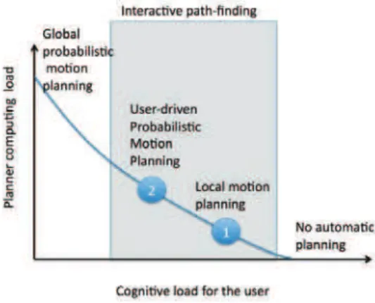
A human brain and an automatic motion planner can cooperate to reduce the time needed to find solution paths. Sharing the control between the user and the planner has certainly much to do with the 3D complexity of the scenario on the one hand and with the abilities of the user on the other hand. It is therefore useful to define different modes of cooperation between user and planner with an adjustable scale of the amount of work required from the planner (and, conversely from the user). Since motion planning is time-consuming, an initial solution enabling real-time collaboration must place very low demand on the planner and then rely heavily on the ability - or reactivity - of the user. In that respect, an initial basic planner consists of generating an interpolation path between the current and final configuration. In this case, it is supposed that the user will find a way out of deadlocks locally and choose a new free configuration from which the planner provides a new path. This simple cooperation (1 in figure 1), in which a high degree of reactivity compensates for low level planning, has proved useful in simple cases.
Fig. 1. User cognitive load and automatic planner computer load in path-finding solutions
When this basic approach is not expected to work prop-erly, it is necessary to rely on more sophisticated planning approaches (2 in figure 1). Motion planners are not generally used in real-time simulation contexts. The solution is generally obtained offline and, in many cases, running time may show large case-dependent variations; this is particularly true for probabilistic motion planners. Now, the main concern is to find, among the numerous approaches, a planning method that can provide a fast or real-time response to a planning request. According to the previous studies ([8], [9]) and considering the case of a 6D configuration space, we decided to use a probabilistic planner ([4], [10]) with a constrained sampling method which can reduce the computation time required for the collision-free path computation [11].
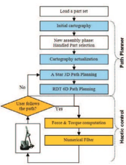
Due to the real-time constraints, the motion planning strat-egy is divided into two main parts in order to distribute
efficiently the computation time between initialization and running time (see figure 2). As an initialization and without any time limit constraint, a 3D space discretization of the position workspace is computed using an unbalanced octal tree. Based on this offline free-space cartography in [xyz], a fast planner in SE(3) is designed in two successive steps: first, a preferred sampling zone is obtained by a customized A star algorithm, then a bi-directive rapidly-exploring deterministic tree (RDT) Algorithm is launched within this zone.
Fig. 2. Time distribution of computation load in the motion planner
A. Discrete Representation of the Position Workspace The first step consists in building a discrete representation of the position workspace. It represents the main part of the required computation time and can be considered as initial-ization; it is therefore carried out prior to the running of the main VR program. This space representation is created using an unbalanced octal tree ([12], [13]) with an adjustable level of depth depending on the size of the handled parts. This structure is used for all the path planning queries in a multi-part assembly simulation and requires updating (” Cartography update” in Figure 3) for each phase of the process: the previous handled part is considered an obstacle and the selected handled part is defined as the new free-flying object. Each leaf of this octal tree contains some useful information such as the name of the parts in collision with the leaf cube and the normal vector of surface in collision. This information is used to reduce the computation time needed for the A star and the RDT algorithms [14].
B. RDT Sampling Zone Computation
This step aims at accelerating the RDT convergence by obtaining a connected reduced sampling zone including the start and goal positions. Since the cartography is unbalanced, a desirable feature of such a preferred sampling zone is to take into account the size of the cubes. Heuristically, a least-distance path with a large free volume around appears as a good sampling zone. Thus the approach consists in adapting
Fig. 3. Overview of the guiding force generation process
an A star strategy - that tries to minimizes distance - to the unbalanced octal tree data structure - in order to maximize volume [15]. Additional heuristics are used for constrained goal and start positions. Finally, this step produces a connected union of different size cubes that constitutes the sampling zone for the RDT.
C. RDT Path-Finding
The final part of the planner tries to find the 6D solution path for the handled part using the 3D sampling zone. For this task we implemented a bi-directive RDT (Rapidly Exploring Random Tree with a deterministic sampling) ([4], [16]). The distance used in the ”get nearest configuration” function of the RDT algorithm was implemented in 6D using a balanced distance named norm6D defined in [14] by:
norm6d(q1, q2) =!µpυp+ µrυr
with υp = ∆x2+ ∆y2+ ∆z2 and υr = ∆θ2x+ ∆θy2+
∆θ2
z and where µp is defined as the weight of the position
component and µrthe weight of the orientation component.
The default RDT algorithm diffuses within a dissemination limit which usually makes it possible to explore the space in small stages. This method of small stage diffusion usually provides good results but requires a considerable number of samples and is time-consuming. In our case, we need to find a solution path using a minimum number of samples. Since the sampling zone has been defined in order to make each sample efficient for free-path research, we decided to implement our RDT method with no diffusion limit. The planning query is defined by the initial and final configurations and the sampling method of our RDT algorithm is restricted to the volume defined by the union of the cubes composing the A star solution.
In order to reduce the time needed to find a solution, the RDT method is implemented with a special heuristic: the initial
samples of the RDT are computed in order to unlock the initial and final configurations which are usually highly constrained. In most mechanical assemblies, the final operation is generally a simple translation. This translation direction can be found using normal vectors of surfaces in collision saved in the octal tree during the initialization stage. In simple cases, this heuristic enables the program to solve mechanical assembly problems using fewer samples.
IV. GUIDINGFORCEGENERATION ANDINTERACTIVITY In most cases, haptics are used in VR simulation for collision simulation and haptic arms provide repulsive forces that prevent motion. In this study, the haptic device is used of course for collision detection, but it is also used to convert the path planning result into a real-time guiding force applied to the user’s hand. Depending on the smoothness of the path provided by the planner, on the current distance to that path, and on control sharing strategy, additional steps need to be defined.
A. Attractive forces computation
First of all, elementary attractive forces −→F = " Fx Fy Fz # and torques − → T = " Tθx Tθy Tθz # are computed from the corresponding components of ∆q = qn−qc, where qc is the current configuration and qn is
the desired following configuration, by the following stiffness laws : Fi=|∆i|∆i $ KF% |∆i| % " ∆x ∆y ∆z #% % FM, i= [x, y, z] Ti=|∆i|∆i & KT|∆i|π TM, i= [θx, θy, θz]
where : FM is the maximum value for the force argument
and TM is the maximum value for a torque argument. The
arguments KF and KT are defined by the user as a function
of his ergonomic preferences. In simple cases, this force computation process can be directly used to guide the user from a current configuration to the final configuration of the handled part.
At the end of the planning part of the program, the path computed by the RDT algorithm is made up of successive collision-free edges linking initial and final configurations. Then, all the data provided by the planner and the 3D virtual world are discrete and the applied attractive force need to be smooth and to avoid steep changes. Thus, the applied force results from a filtering that weights past elementary forces in the following way :
Ff= 2 (N + 1) × N × N−1 ' i=0 "(N − i) × F(n−i) #
B. Shared control strategy
The shared control strategy must provide an help to the user through force guidance along or – practically – around a path computed by the path planner. It must also enables the user with the possibility to move away from this path. And, finally, it must detect that the user wants really to explore a different
zone of the workspace and then start a new path-finding starting from the current configuration of the part. Basically, this is realized by defining two zones in the workspace, the following zone which is a given norm neighbourhood of the planned path and the rest of the workspace, and by associating different control and detection strategies [15].
In the assembly and disassembly simulation context, the user handles a part and moves freely up to the end of the collision-free path computation. So, once a path has been computed, the current configuration of the handled part can be outside the following zone and a first force is computed to guide the user towards it. This force is based on the differential vector ∆q between the current configuration of the handled part and the nearest configuration on the path. The delay induced by the numerical filter enables a progressive guiding force increase which provides ergonomic user guidance.
Once this zone is reached, the guiding force is applied to make the user follow the path. In order to anticipate the tracking of the discrete path provided by the planner, the force applied to the user results from the above described filtering and from the predictive component, inspired from [17]:
F = 2 (N + 1) × N × N−1 ' i=0 "(N − i) × F(n+i) #
The applied force is the result of a filtering through a windows centered at the next configuration qn.
The user has the capability to deviate slightly from the ideal path corresponding to the applied force. If he does not agree with the path previously found and attempts to follow another path, this intention is detected when he goes out of the following zone. Since the distance between the configuration of the handled part and the nearest configuration on the path is computed in relation to a moving point on the path, it conveys information concerning current state and tendency, position and velocity. Once the handled part quits the following zone, the real-time section of the path planner is restarted using the current configuration of the handled part as the new initial condition of the A star algorithm (Figure 3). Then, the RDT roadmap is improved with new samples and another path is computed.
V. RESULTS
The VR system used to carry out the experiments is composed with a large screen using passive stereoscopy for the 3D visualization, an AR Track system for the user view-point capture, a Virtuose 6D 35-45 as force feedback device for the part handling and a single computer with a 3.73GHz CPU and 2Go RAM to run the simulation. The VR software are Virtools Dev 4.0 and the Interactive Physic Pack based on V.P.S. [18]. The tests presented were carried out using the collision checker of Virtools (default 3D Entity Face/Face static intersection checker).
A. Fast planning Tests
First, in order to compare our path planner to an existing path planning solution, a standard bi-directive RRT planner
[4] is implemented without diffusion limit and executed on the same simulation context using 50 simulations of each planning query. The simulation scene contains 16.814 objects with a total weight of 3.878.806 faces. The computed workspace is a large cube (4.5 m × 4.5 m × 4.5 m) and the moving entity is a power component. As shown in Figure 4, this complex simulation contains a narrow passage around the final configuration.
In this context, the original RRT method needs a lot of samples to compute a solution path. It is also very time-consuming especially when it samples close to the obstacles as shown in Table I, due to the complexity of the scene.
Number of samples Time needed
Mean 593 12470 ms
Standard deviation 270 5895 ms TABLE I
TIME AND NUMBER OF SAMPLES NEEDED BY THERRT ALGORITHM
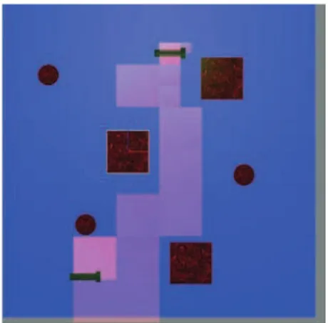
Concerning our solution, the A star method needs to per-form subdivision of the final configuration cube in order to find a correct solution. This cannot be done in real time but remains very fast as seen in Table II. It also defines a correct free-area for RDT sampling illustrated in Figure 4.
Time needed Mean 1020 ms Standard deviation 240 ms
TABLE II
TIME NEEDED TO PERFORM THEASTAR RESEARCH
Using an A star result to constrain RDT sampling makes it possible to decrease the time consumed in collision detection by sampling free zones. The resulting reduction in collision test costs in the RDT algorithm enables fast 6D path planning to be performed in very complex environments as shown in Table III. Also, the solution path found using this method is non-minimal in length but enables ergonomic handling of the part by balancing length minimization and clearance to obstacles as shown in Figure 5. Table III shows that the full 6D path cannot be computed in real time and this causes latency in the simulation. This drawback could be dealt with by parallelizing the RDT algorithm [10].
Number of samples Time needed
Mean 19 720 ms
Standard deviation 23 1300 ms TABLE III
TIME AND NUMBER OF SAMPLES NEEDED BY THERDT ALGORITHM
Finally, fast motion planning solution is provided even for complex CAD scenes. A small latency is observed with the current hardware but the obtained performances show that real-time re-planning is feasible with this kind of approach in complex environments.
B. Interactive path-finding and re-planning
Then, we illustrate what happens if the user does not want to follow the path proposed by the automatic planner and tries to search for another solution. In the environment depicted by the figures 6 and 7, the successive phases occur without latency for the user. In particular, when the user escapes from the first solution in figure 8, the resulting attractive force field associated to the path in figure 9 is generated at the display frame rate of 24 ms.
VI. CONCLUSION AND FUTURE WORK
This paper presents a new paradigm based on visuo-haptic collaborative work between a user in a VR context and automatic motion planners for interactive path-finding. A generic structure is proposed and a particular instance has been developed and illustrated in particular in assembly simulation scenarios for CAD scenes. In the near future, many questions would merit deeper understanding and further study. In particular, different modes of asynchronous activation of the planners must be compared including active user command or detection of user intention by considering mixed criteria based on head motion tracking and haptics.
REFERENCES
[1] S. Jayaram, Y. Wang, U. Jayaram, K. Lyons, P. Hart, Vade: A Virtual As-sembly Design Environment, in IEEE Transactions on Computer Graphics and Applications, 19(6), pp 44-50, 1999.
[2] C. Chabal, C. Megard, L. Sibile. Emm-3d: a virtual environment for eval-uating maintainability from cad models, in 7th International Conference on Virtual Reality (VRIC 2005), 2005.
[3] J.-C. Latombe. Robot Motion Planning, Springer, 1990.
[4] S. M. Lavalle. Planning Algorithms, Cambridge University Press, 2006. [5] H. Choset, K. M. Lynch, S. Hutchinson, G. Kantor, W. Burgard, L. E.
Kavraki, S. Thrun. Principles of Robot Motion: Theory, Algorithms,and Implementations, MIT Press, Cambridge, MA, 2005.
[6] P. Svestka, M. Overmars. Probabilistic path planning, in J.-P. Laumond (Ed.), Robot Motion Planning and Control, Lect. Notes in Control and Information Sciences, Vol. 229, pp. 255-304, Springer-Verlag, 1998. [7] D. Galeano, S. Payandeh. Artificial and natural force constraints in
haptic-aided path planning, in IEEE International Workshop on Haptic Audio Visual Environments and their Applications (HAVE), Ottawa, Ontario, Canada, pp 45-50, 1-2 October 2005.
[8] L. E. Kavraki, P. Svestka, J-C. Latombe, M. Overmars. Probabilistic roadmaps for path planning in high-dimensional configuration spaces, IEEE Transactions on Robotics and Automation, 12(4), pp 566-580, 1996. [9] O. B. Bayazit, G. Song, N. M. Amato. Enhancing randomized motion planners: Exploring with haptic hints, Autonomous Robots, 10(2), pp 163-174, 2001.
[10] I. Aguinaga, D. Borro, L. Matey. Parallel RRT based path planning for selective disassembly planning, International Journal of Advanced Manufacturing Technology 36, pp 1221-1233, 2008.
[11] J. P. van den Berg, M. H. Overmars. Using workspace information as a guide to non-uniform sampling in probabilistic roadmap planners, The International Journal of Robotics Research 24(12), pp 1055-1071, 2005. [12] Y. Kitamura, F. Kishino. A parallel algorithm for octree generation from polyhedral shape representation, In Proc. of the 13th International Conference on Pattern Recognition, vol. 4., pp 303-309, Vienna, Austria, August 1996.
[13] S. F. Frisken, R. N. Perry. Simple and efficient traversal methods for quadtrees and octrees, Journal of Graphics Tools 7(7), 2002.
[14] N. Ladeveze, J-Y. Fourquet, B. Puel, M. Taix, Haptic Assembly and Disassembly Task Assistance using Interactive Path Planning, pp.19-25, in IEEE Virtual Reality Conference, Lafayette, LA, March 2009. [15] N. Ladeveze, J-Y. Fourquet, B. Puel, Interactive path planning for haptic
assistance in assembly tasks, Computer and Graphics, 34(1), pp 17-25, 2010.
[16] J. Kuffner, J.J., S. LaValle. RRT-connect: An efficient approach to single-query path planning, in IEEE International Conf. on Robotics and Automation, vol. 2, pp. 995-1001, San Francisco, April 2000.
[17] B. Forsyth, K. Maclean. Predictive haptic guidance: intelligent user assis-tance for the control of dynamic tasks, IEEE Transactions on Visualization and Computer Graphics, 12(1), pp 103-113, 2006.
[18] W. A. MCNeely, K. D. Puterbaugh, J. J. Troy. Six degree of freedom haptic rendering using voxel sampling, in Proc. of the ACM SIGGRAPH, pp 401 - 408,1999.
Fig. 4. A Star result for power component insertion in the vehicle
Fig. 5. Path found by the RDT method using the A star algorithm result
Fig. 6. First A star zone found by the path-planner
Fig. 7. First path found by the path-planner
Fig. 8. New direction of search indicated by the force exerted by the user (red arrow), detected by the haptic guidance system and new A star zone found by the path planner