Influence Of Broken Rotor Bars Location In The Squirrel Cage Induction Motor Using Finite Element Method
10
0
0
Texte intégral
(2) N. Halem et al.. J. Fundam Appl Sci. 2013, 5(1), 110-119. 111. For that, a model closer to reality considering faults conditions must be established. An analytical analysis method based on the rotating field theory and coupled circuit was used [1]. In works, where the machine inductances are calculated and the machine performance is studied under faulty conditions, the Winding Function Approach (WFA), is used, where several assumptions and approximations of the actual machine layout are made, like the effects of stator teeth and slots, which are omitted in the calculations [2]. The modeling with finite element method represents a high fidelity electromagnetic behaviour which leads to more precise results than other models, as the actual geometry and winding layout of the machine are used. The consideration of the behaviour of the local electromagnetic induction machine provides a more accurate modeling. The numerical solution of Maxwell's equations governing the behaviour of electromagnetic fields and the consideration of the equations representing the electrical supply circuit of the machine reduces the simplifications made in the classical models. In analysis of induction motors, the input current, not the voltage, is usually used. The voltage source is more suitable than current source. The external circuit that represents the electrical sources and circuit components are coupled to the FEM. Only the terminal voltages applied to the motor are required as known input quantities, and the total terminal currents are the unknowns to be evaluated. The use of time-stepping finite elements is the most precise way, up to date, for modeling the coupled field-circuits and motion of induction motors, accounting for both saturation, time and space harmonics. Indeed, the modeling of rotor mechanical motion and stator field source variation simultaneously allows coupling the instantaneous fields of stator and rotor [3]-[4]. This paper presents the transient state modeling of cage induction motors using the coupled electric circuit with 2D finite element electromagnetic field analysis. The flux 2D magnetic analysis software is used for calculating the magnetic field of an induction motor for the healthy rotor, and broken bars. In aim to show the influence of the broken bars location upon the amplitudes of harmonics due to the fault, seven for different positions are simulated at rated load.. 2. TSFE ANALYSIS OF INDUCTION MOTOR BASED CIRCUIT-COUPLED METHOD Generally the induction motor is excited by an external voltage source, from many models based on finite elements method, only the Circuit-Coupled Finite Element Method (CircuitCoupled FEM) can close this reality, here the external electric circuit which contains the three.
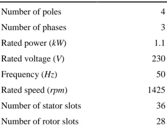
(3) N. Halem et al.. J. Fundam Appl Sci. 2013, 5(1), 110-119. 112. voltage sources is coupled to the finite element domain which contains the magnetic circuit of the electric machine [5]-[6]-[7]. In table 1, specifications of the studied induction motor. Table 1. Specifications of studied induction motor Number of poles. 4. Number of phases. 3. Rated power (kW). 1.1. Rated voltage (V). 230. Frequency (Hz) Rated speed (rpm). 50 1425. Number of stator slots. 36. Number of rotor slots. 28. For Preston [8] the transient magnetic field in terms of magnetic vector potential A , the reluctivity, conductivity , and current density J can be expressed as:. A A A J x x y y t. (1). The last term represents current induced in conducting material when flux changes with time. For Salon [9] and Lombard [10] the full transient performance can be obtained by accounting for the mechanical equation of the motor and the transient motional induced eddy current in the rotor bars can't be neglected as in equation (1), the complete system is based on the differential equation in compact form: A A E V A t . (2). Where V is the speed of the moving parts, E is the electrical scalar potential applied by the external circuit. So the problem is considered as transient alike. When the motor is loaded the voltage time step must be accompanied by rotor motion corresponding to the slip. The time step must be sufficiently small to ensure that the effects of slotting and static air gap eccentricity are accurately modeled, also to obtain a suitable frequency resolution for the application of Fast Fourier Transform (FFT) [11].. 3. SIMULATION RESULTS.
(4) N. Halem et al.. J. Fundam Appl Sci. 2013, 5(1), 110-119. 113. In this paper, the induction motor is simulated under rated conditions. An induction machine rotor asymmetry introduced by broken bars produces spectrum lines of stator current at frequencies:. fbb1 1 2ks f s. (3). Where f s is the electrical supply frequency, s is the slip, k=1, 2, 3, ... Figure 1a, b shows the stator current spectrum of healthy and faulty rotor. According to fig. 1a it can be clearly shown that the stator current spectrum for healthy state is very rich by the expectation harmonic components [12] such; principal slot harmonics at 616.2Hz and 716.2Hz, saturation harmonics (150Hz, 250Hz, 350Hz, ...) and saturation related harmonics (516.2Hz, 816.2Hz, 916.2Hz, ...), the appearing of those harmonic components signifies that the finite element model used in this paper closers the reality of the induction motor. (a). 0. Amplitude (dB). -20 -40 -60 -80 -100. 0. 100. 200. 300. 400 500 600 Frequency (Hz). 700. 800. 900. 1000. (b). 0. Amplitude (dB). -20 -40 -60 -80 -100. 0. 100. 200. 300. 400 500 600 Frequency (Hz). 700. 800. 900. 1000. Fig. 1. Stator current spectrum at steady state: a healthy rotor; b one broken bar.
(5) N. Halem et al.. J. Fundam Appl Sci. 2013, 5(1), 110-119. 114. In case of broken rotor bar as presented in fig. 1b, the rotor is electrically asymmetric and the backward rotating field is created. The current spectrum reveals sidebands expected around the supply frequency given by (3) [13]-[14]. Figures 2a, b, c, d and 3e, f, g, h, show the stator current spectrums in steady state according with the corresponding magnetic flux distribution for healthy and faulty rotor at the transient state. When the slip is large, the eddy current shows a large value. This high value of slip is necessary to illustrate the effects of the broken bars on the field. The concentration of magnetic flux is observed around the broken bars and creates asymmetric magnetic flux distribution [15]-[14]. As shown in the fig. 2a, for healthy rotor; there are no index signatures of broken bar fault around fundamental harmonic. As expected in the fig. 2b, the fault signatures of one broken bar are appeared very clearly around fundamental harmonic. However when one bar breaks, its adjacent bars expose more to the fault due to the larger stress on the bars. Following the breakage of the first bar, the adjacent bars may break after a short period [13]. Figure 2c chows the stator current spectrum for two adjacent broken bars under one pole, while the fig. 2d presents one broken bar on one pole and one broken bar on adjacent pole, the amplitude of harmonic component 1 2s f s is increased from -34.99dB to -29.80dB, also the amplitude of harmonic component 1 2 s f s is increased from -31.33dB to -28.90dB, Comparison of fig. 2b and 2c indicates that the amplitudes of harmonic components. 1 2s f s. are increased when the number of broken bar increased. Moreover comparison of. fig. 2c and 2d indicates that the higher increasing of the amplitudes of harmonic components. 1 2s f s. occurs when the two adjacent broken bars located at the same pole.. Figure 3e presents the stator current spectrum when the first and the eight bars are broken; one broken bar on one pole and one broken bar on adjacent pole, the amplitudes of harmonic. components 1 2 s f s are -31.56dB and -29.94dB. Figure 3f presents the stator current spectrum when the first and the fifteenth bars are broken; one broken bar on one pole and one broken bar on opposite pole, the amplitudes of harmonic. components 1 2 s f s are -32.46dB and -29.99dB, it is clearly shown that the amplitudes of harmonic components 1 2 s f s have no so much difference with the previous case, only amplitude of harmonic component 1 2s f s decreases from -31.56dB to -32.46dB..
(6) N. Halem et al.. J. Fundam Appl Sci. 2013, 5(1), 110-119. Amplitude (dB). 0. (a). -40 -60. Is o v a lu e s R e s u lts Quant i t y : Equi f l ux Weber Ti m e ( s. ) : 0, 002 Pos ( deg) : - 64, 156E- 3 Li ne / Val ue 1 / - 585, 70429E- 6 2 / - 524, 05073E- 6 3 / - 462, 39715E- 6 4 / - 400, 74359E- 6 5 / - 339, 09004E- 6 6 / - 277, 43645E- 6 7 / - 215, 7829E- 6 8 / - 154, 12933E- 6 9 / - 92, 47578E- 6 10 / - 30, 82221E- 6 11 / 30, 83135E- 6 12 / 92, 48492E- 6 13 / 154, 13847E- 6 14 / 215, 79204E- 6 15 / 277, 44559E- 6 16 / 339, 09918E- 6 17 / 400, 75273E- 6 18 / 462, 40629E- 6 19 / 524, 05987E- 6 20 / 585, 71342E- 6. 0. 10 20 30 40 50 60 70 80 90 100 Frequency (Hz). Amplitude (dB). 0. (b) (1-2s)f. -20. s. -34.45dB. (b). (1+2s)f. s. -34.83dB. -40 -60 -80. Is o v a lu e s R e s u lts Quant i t y : Equi f l ux Weber Ti m e ( s. ) : 0, 002 Pos ( deg) : - 65, 7E- 3 Li ne / Val ue 1 / - 578, 74754E- 6 2 / - 516, 47087E- 6 3 / - 454, 19423E- 6 4 / - 391, 91757E- 6 5 / - 329, 6409E- 6 6 / - 267, 3642E- 6 7 / - 205, 08755E- 6 8 / - 142, 81087E- 6 9 / - 80, 53421E- 6 10 / - 18, 25753E- 6 11 / 44, 01914E- 6 12 / 106, 29581E- 6 13 / 168, 57247E- 6 14 / 230, 84915E- 6 15 / 293, 12581E- 6 16 / 355, 4025E- 6 17 / 417, 67917E- 6 18 / 479, 95584E- 6 19 / 542, 23248E- 6 20 / 604, 50914E- 6. 0. 10 20 30 40 50 60 70 80 90 100 Frequency (Hz). 0 Amplitude (dB). (a). -20. -80. (c) (1-2s)f s -29.80dB. -20. (c). (1+2s)f. s. -28.90dB. -40 -60 -80. 0. 10 20 30 40 50 60 70 80 90 100 Frequency (Hz). 0 Amplitude (dB). 115. (d) (1-2s)f. s. -20. -34.99dB. Is o v a lu e s R e s u lts Quant i t y : Equi f l ux Weber Ti m e ( s. ) : 0, 002 Pos ( deg) : - 66, 456E- 3 Li ne / Val ue 1 / - 576, 0963E- 6 2 / - 512, 52393E- 6 3 / - 448, 95158E- 6 4 / - 385, 37924E- 6 5 / - 321, 8069E- 6 6 / - 258, 23456E- 6 7 / - 194, 66222E- 6 8 / - 131, 08988E- 6 9 / - 67, 51753E- 6 10 / - 3, 94519E- 6 11 / 59, 62716E- 6 12 / 123, 1995E- 6 13 / 186, 77185E- 6 14 / 250, 34419E- 6 15 / 313, 91653E- 6 16 / 377, 48888E- 6 17 / 441, 06122E- 6 18 / 504, 63359E- 6 19 / 568, 2059E- 6 20 / 631, 77827E- 6. (d). (1+2s)f. s. -31.33dB. -40 Is o v a lu e s R e s u lts Quant i t y : Equi f l ux Weber Ti m e ( s. ) : 0, 002 Pos ( deg) : - 62, 118E- 3 Li ne / Val ue 1 / - 595, 30977E- 6 2 / - 532, 12099E- 6 3 / - 468, 93221E- 6 4 / - 405, 74343E- 6 5 / - 342, 55465E- 6 6 / - 279, 36584E- 6 7 / - 216, 17705E- 6 8 / - 152, 98826E- 6 9 / - 89, 79948E- 6 10 / - 26, 61068E- 6 11 / 36, 57811E- 6 12 / 99, 7669E- 6 13 / 162, 95568E- 6 14 / 226, 14448E- 6 15 / 289, 33326E- 6 16 / 352, 52207E- 6 17 / 415, 71085E- 6 18 / 478, 89963E- 6 19 / 542, 08841E- 6 20 / 605, 27719E- 6. -60 -80. 0. 10 20 30 40 50 60 70 80 90 100 Frequency (Hz). Fig. 2. Stator current spectrum at steady state and flux distribution at transient state for different cases for distribution of broken bars under poles: a healthy rotor; b one broken bar; c two adjacent broken bars on one pole; d two non adjacent broken bars, one broken bar on one pole and one broken bar on adjacent pole.
(7) N. Halem et al.. J. Fundam Appl Sci. 2013, 5(1), 110-119. Amplitude (dB). 0. (e) (1-2s)f. -20. s. (1+2s)f. s. -29.94dB. -31.56dB. -60 Is o v a lu e s R e s u lts Quant i t y : Equi f l ux Weber. 0. Amplitude (dB). (f) (1-2s)f. -20. Ti m e ( s. ) : 0, 002 Pos ( deg) : - 67, 109E- 3 Li ne / Val ue 1 / - 579, 06326E- 6 2 / - 517, 08869E- 6 3 / - 455, 11409E- 6 4 / - 393, 13952E- 6 5 / - 331, 16495E- 6 6 / - 269, 19038E- 6 7 / - 207, 21581E- 6 8 / - 145, 24124E- 6 9 / - 83, 26667E- 6 10 / - 21, 2921E- 6 11 / 40, 68247E- 6 12 / 102, 65704E- 6 13 / 164, 63161E- 6 14 / 226, 60618E- 6 15 / 288, 58075E- 6 16 / 350, 55532E- 6 17 / 412, 52989E- 6 18 / 474, 50446E- 6 19 / 536, 47906E- 6 20 / 598, 45363E- 6. 10 20 30 40 50 60 70 80 90 100 Frequency (Hz). 0. (f). (1+2s)f. s. s. -29.99dB. -32.46dB. -40 -60 -80. 0. 10 20 30 40 50 60 70 80 90 100 Frequency (Hz). 0 Amplitude (dB). (e). -40. -80. (g) (1-2s)f. s. -20. -26.64dB. Is o v a lue s R e s u lts Quant i t y : Equi f l ux Weber Ti m e ( s. ) : 0, 002 Pos ( deg) : - 67, 163E- 3 Li ne / Val ue 1 / - 556, 86093E- 6 2 / - 495, 90383E- 6 3 / - 434, 94676E- 6 4 / - 373, 98969E- 6 5 / - 313, 03262E- 6 6 / - 252, 07552E- 6 7 / - 191, 11845E- 6 8 / - 130, 16138E- 6 9 / - 69, 2043E- 6 10 / - 8, 24723E- 6 11 / 52, 70985E- 6 12 / 113, 66692E- 6 13 / 174, 6231E- 6 14 / 235, 58107E- 6 15 / 296, 53814E- 6 16 / 357, 49524E- 6 17 / 418, 45231E- 6 18 / 479, 40938E- 6 19 / 540, 36645E- 6 20 / 601, 32355E- 6. (g). (1+2s)f. s. -26.28dB. -40 -60 -80. 0. 10 20 30 40 50 60 70 80 90 100 Frequency (Hz). 0 Amplitude (dB). 116. (h) (1-2s)f. s. -20. -26.28dB. Is o v a lu e s R e s u lts Quant i t y : Equi f l ux Weber Ti m e ( s. ) : 0, 002 Pos ( deg) : - 67, 69E- 3 Li ne / Val ue 1 / - 575, 32382E- 6 2 / - 512, 1312E- 6 3 / - 448, 9386E- 6 4 / - 385, 74601E- 6 5 / - 322, 55342E- 6 6 / - 259, 36079E- 6 7 / - 196, 1682E- 6 8 / - 132, 97561E- 6 9 / - 69, 783E- 6 10 / - 6, 59041E- 6 11 / 56, 6022E- 6 12 / 119, 79479E- 6 13 / 182, 98739E- 6 14 / 246, 17999E- 6 15 / 309, 37258E- 6 16 / 372, 56521E- 6 17 / 435, 7578E- 6 18 / 498, 95036E- 6 19 / 562, 14299E- 6 20 / 625, 33561E- 6. (h). (1+2s)f. s. -25.33dB. -40 -60 -80. 0. 10 20 30 40 50 60 70 80 90 100 Frequency (Hz). Is o v a lu e s R e s u lts Quant i t y : Equi f l ux Weber Ti m e ( s. ) : 0, 003 Pos ( deg) : - 150, 522E- 3 Li ne / Val ue 1 / - 948, 46461E- 6 2 / - 855, 18241E- 6 3 / - 761, 90027E- 6 4 / - 668, 61807E- 6 5 / - 575, 33593E- 6 6 / - 482, 05376E- 6 7 / - 388, 77159E- 6 8 / - 295, 48942E- 6 9 / - 202, 20726E- 6 10 / - 108, 92509E- 6 11 / - 15, 64292E- 6 12 / 77, 63925E- 6 13 / 170, 92141E- 6 14 / 264, 20358E- 6 15 / 357, 48575E- 6 16 / 450, 76793E- 6 17 / 544, 05007E- 6 18 / 637, 33227E- 6 19 / 730, 61441E- 6 20 / 823, 89661E- 6. Fig. 3. Stator current spectrum at steady state and flux distribution at transient state for different cases for distribution of broken bars under poles: e two non adjacent broken bars, one broken bar on one pole and one broken bar on adjacent pole; f two non adjacent broken bars, one broken bar.
(8) N. Halem et al.. J. Fundam Appl Sci. 2013, 5(1), 110-119. 117. on one pole and one broken bar on opposite pole; g three broken bars, two broken bars on one pole and one broken bar on adjacent pole; h three adjacent broken bars under one pole. Figure 3g shows the stator current spectrum when the first, the second and the eight bars are broken; it mean two broken bars on one pole and one broken bar on adjacent pole, the amplitudes of harmonic components 1 2 s f s are -26.64dB and -26.28dB. Comparison of fig. 3e, f and 3g indicates an important increasing in the amplitudes of harmonic components 1 2 s f s , this increasing is caused by the added broken bar. It is necessary to note that some research works witch based on analytic method to modeling the faulty induction motor, affirmed that when two broken bars spaced electrically of / 2 , the amplitudes of harmonic components 1 2 s f s are very low [17]-[18]. In this paper, the simulation results obtained from faulty induction motor model using TSFE method (fig. 3e, f, and g) prove the contrary, the amplitudes of harmonic components 1 2 s f s in all cases are very important. As shown in fig. 3h which presents the stator current spectrum of faulty induction motor with three adjacent broken bars, the successive breakage of three bars leads to more asymmetrical flux distribution, and higher local saturation, more variations of the flux density and larger harmonic components of the stator current are realized.. 4. CONCLUSION This paper presents the circuit coupled finite element method used to modeling the ThreePhase Squirrel Cage Induction Motor. For this purpose, the time-stepping finite element method (TSFE) was proposed. The broken rotor bar fault is simulated for different positions under poles. It was investigated that the broken bar location affects upon the amplitude of harmonic fault. It was shown that the amplitudes of harmonics due to broken bars located on one pole are larger than the case in which the broken bars are distributed on different poles. Also, the amplitudes of harmonics due to broken bars are larger when broken bars are adjacent..
(9) N. Halem et al.. J. Fundam Appl Sci. 2013, 5(1), 110-119. 118. 5. REFERENCES [1] Ghoggal A., Sahraoui M., Zouzou S. E, 2008. Analytical and experimental study of a squirrel cage induction motors with rotor bar faults. Advances in Modelling, Measurement and Control,A : General Physics and Electrical Applications, AMSE, vol. 81(2):. 43-60. [2] Zouzou S. E., Ghoggal A., Aboubou A., Sahraoui M., Razik H, 2005. Modelling of induction machines with skewed rotor slots dedicated to rotor faults, presented at the IEEE International Symposium on Diagnostics for Electric Machines, Power Electronics and Drives, Vienna, Austria, 7-9 Sep 2005. [3] Ouazir Y., Takorabet N., Ibtiouen R., Benhaddadi M, 2009. Time-stepping FE analysis of cage induction motor with air-gap interface coupling taking into account phase-belt harmonics. IEEE Trans. Magn, 45: 1384-1387. [4] Ying X., 2009. Characteristic performance analysis of squirrel cage induction motor with broken bars. IEEE Trans. Magn, 45: 759-766 [5] Sadowski N., Carlson R., Arruda S. R., Silva C. A., Mazenc M. L, 1995. Simulation of single-phase induction motor by general method coupling field and circuit equations. IEEE Trans Magnetics 31(3): 1908-1911. [6] Zouzou S. E., Khelif S., Halem N., Sahraoui M, 2011. Analysis of induction motor with broken rotor bars using circuit-field coupled method. International conference on electric power and Energy Conversion Systems, Sharjah, UAE: 15-17. [7] Halem N., Zouzou S. E., Srairi K, 2011. Analysis of induction motor with broken bars and constant speed using circuit-coupled method. Rev. sci. fond. app, 3(2): 106-120. [8] Preston T. W., Reece A. B. J., Sangha P. S, 1988. Induction motor analysis by timestepping technique. IEEE Trans Magnetics 24(1): 471-474. [9] Salon S. J., Burow D. W., Ashly R. E., Ovacik L., DeBotoli M. J, 1993. Finite element analysis of induction machine in the frequency domain. IEEE Trans Magnetics 29(2): 14381441. [10] Lombard P., Meunier G, 1992. A general method for electric and magnetic coupled problem in 2D and magnetodynamic domain. IEEE Trans Magnetics 28(2): 1291-1294. [11] Thomson W. T., Barbour A, 1998. On-line current monitoring and application of finite element method to predict the level of static airgap eccentricity in three-phase induction motors. IEEE Trans Energy Conversion 13(4): 347-357. [12] Joksimovic G., Riger J., Wolbank T., Peric N., Vasak M, 2011. Stator line current spectrum content of a healthy cage rotor induction machine. SDEMPED, Bologna, Italy..
(10) N. Halem et al.. J. Fundam Appl Sci. 2013, 5(1), 110-119. 119. [13] Faiz J., Ebrahimi B. M, 2009. Locating rotor broken bars in induction motors using finite element method. Energy Conversion and Management, 50: 125-131. [14] Riera-Guasp M., Cabanas M. F., Antonino-Daviu J. A., Pineda-Sanchez M., Garcia C. H. R, 2010. Influence of nonconsecutive bar breakages in motor current signature analysis for the diagnosis of rotor faults in induction motors. IEEE Trans. Energy Convers, 25: 80-89. [15] Fiser R., Ferkolj S, 2000. Application of a finite element method to predict damaged induction motor performance. IEEE Trans. Magn, 37(1): 3635-3639 [16] Aileen C. J., Nagarajan S., Reddy S. R, 2011. Detection of broken bars in three phase squirrel cage induction motor using finite element method, presented at the International Conference on Emerging Trends in Electrical and Computer Technology (ICETECT), Nagercoil, India, 23-24 Mar. 2011. [17] Abed A, 2002. Contribution à l'étude et au diagnostic de la machine asynchrone. PhD thesis, Université Henri Poincaré, Nancy-1, mars 2002. [18] Sahraoui M, 2003. Contribution au diagnostic d'une machine asynchrone triphasée à cage. Magister thesis. Université de Biskra, 2003.. How to cite this article Halem N, Zouzou S E, Srairi K and Guedidi S. Influence of broken rotor bars location in the squirrel cage induction motor using finite element method. J Fundam Appl Sci. 2013, 5(1), 110-119..
(11)
Figure


Documents relatifs
To detect broken bars, measurements of stator voltages and currents are processed by an Extended Kalman Filter for the speed and rotor resistance
Under abnormal conditions, for example in the presence of rotor cage faults such as broken bars, (9) and (10) are no longer valid, because the induction motor supply
Abstract: The fault of broken rotor bars in a three phase induction motor is diagnosed by using the wavelet Packet analysis. In this paper Daubechies wavelet is selected as the
Abstract: The fault of broken rotor bars in a three-phase induction motor is diagnosed by using the wavelet Packet analysis. In this paper Daubechies wavelet is selected as the
Several published works are related to rotor bar failures in squirrel cage induction motors are based on machine current signature analysis [5].In this way fast
Analytical variation of the negative (left), the third positive (middle) and the third negative (right) sequences harmonics according to the load percentage under different
Consequently, whilst the campaign to restore Palestinian control over the large towns saw a certain return to order, the new security arrangements imposed by
Although this is not often the case with low-power machines and rather large series (those whose dimensions are a priori the most sensitive to eco- design criterions as we
