HAL Id: tel-03032643
https://tel.archives-ouvertes.fr/tel-03032643
Submitted on 1 Dec 2020
HAL is a multi-disciplinary open access archive for the deposit and dissemination of sci-entific research documents, whether they are pub-lished or not. The documents may come from teaching and research institutions in France or abroad, or from public or private research centers.
L’archive ouverte pluridisciplinaire HAL, est destinée au dépôt et à la diffusion de documents scientifiques de niveau recherche, publiés ou non, émanant des établissements d’enseignement et de recherche français ou étrangers, des laboratoires publics ou privés.
and energy recovery
Jenny Juliana Pena
To cite this version:
Jenny Juliana Pena. Study of chars prepared from biomass wastes : material and energy recovery. Chemical and Process Engineering. Ecole nationale supérieure Mines-Télécom Atlantique, 2018. En-glish. �NNT : 2018IMTA0104�. �tel-03032643�
i
Acknowledgments
I wish to express my gratitude to Professor Claire GÉRENTE and Dr Audrey VILLOT for allowing me to prepare my doctorate in the best conditions. I want to thank them especially for their efforts and the support they have shown me throughout this study under their direction.
I am very honored by the presence as reviewers of Professor Pierre LE CLOIREC and Professor Marco BARATIERI for having accepted to participate in this jury. I would like to thank Professor Manuel RODRIGUEZ of Universidad de Los Andes and Professor Laurence LE COQ for having accepted to participate in this jury.
This work was done with the financial support of L’Agence de l’Environnement et de la Maîtrise de l’Energie (ADEME) and Region Pays de la Loire. I thank M. Simon THOUIN for taking part in the jury of this thesis in representation of ADEME. I am also very grateful to all the teams of the professors of the Department, secretaries (especially, Mme Dominique Briand), technicians (particularly, Mr Eric Chevrel), colleagues and friends. Finally, I would like to express my gratitude to my dear cousin Carolina Gutierrez and my family, whose support has been essential throughout my studies, especially during this work.
ii
Scientific production
Scientific articles
Peña J., Villot A., Gérente C. Pyrolysis chars and physically activated carbons prepared from buckwheat husks for catalytic purification of syngas. Submitted to Biomass and Bioenergy Journal. September 2018 (Annexe 6).
Oral presentations
Peña J., Villot A., Gérente C. Valorization of millet and buckwheat husks chars and activated carbons in H2S removal from biogas. 7th International conference on Engineering for Waste and Biomass Valorization – Prague, Czech Republic. 02 – 05 July 2018.
Peña J., Goh K., Villot A., Gérente C., Le Coq L. Biomass valorization by means of thermochemical conversion processes: pyrolysis and surface activation. 7th International Symposium on Carbon for Catalysis, Strasbourg, France, 12 – 16 June, 2016.
Posters
Peña J., Villot A., Gérente C. Buckwheat husk based materials as new catalyst in syngas upgrading. 7th International conference on Carbon for Energy Storage and Environmental Protection – Lyon, France. 23 – 26 October 2017.
Peña J., Villot A., Gérente C. Raw and activated char’s selectivity in syngas upgrading application: Implementation in a fixed bed column. 16éme Congrès de la Société Français de Génie des Procédés (SFGP 2017) – Nancy, France. 11 – 13 July 2017.
M. Elsayed, Peña J., Villot A., Gérente C. Y. Andres. Energy potential from buckwheat husks through a thermochemical and biochemical approaches. 25th European Biomass Conference and Exhibition - Stockholm, Sweden. 12 – 15 June 2017.
Peña J., Villot A., Gérente C. Upgrading of pyrolysis chars in syngas purification: Characterization and implementation in a fixed bed column. 25th European Biomass Conference Exhibition - Stockholm, Sweden. 12 – 15 June 2017.
iii
Acronyms
AC: Activated carbon AD: Anaerobic digestion
AEE: Apparent energy efficiency
AEEelec: Apparent energy efficiency which takes into account the electrical consumption AAEM: Alkali and Alkaline Earth Metals
AS: Amine scrubbing BH: Buckwheat Husk
BH-Char: Pyrolysis char from buckwheat husk
BH-CO2: Activated char prepared from CO2 activation of buckwheat husk BH-H2O: Activated char prepared from steam activation of buckwheat husk CHP: Combined Heat and Power
Dp: Pore diameter EB: Ethylbenzene
EBC: European Biochar Certificate ESP: Electrostatic Precipitator
FAO: Food and agriculture Organization of United Nations GC: Gas Chromatography
HHV: Higher Heating Value
HPWS: High Pressure Water Scrubbing IEA: International Environment Agency ISS: Inorganic Solvent Scrubbing
IUPAC: International Union of Pure and Applied Chemistry LHV: Lower Heating Value
MH: Millet Husk
MH-Char: Pyrolysis char from millet husk
MH-CO2: Activated char prepared from CO2 activation of millet husk MH-H2O: Activated char prepared from steam activation of millet husk MT: Mine tailings
NER: Net Energy Ratio
OPS: Organic Physical Scrubbing PAH: Poly-aromatic Hydrocarbons PSA: Pressure Swing Adsorption
iv RH: Relative Humidity
SEM: Scanning Electron Microscopy SOFC: Solid Oxide Fuel Cells
TGA: Thermo-gravimetric Analysis VOC: Volatile Organic Compounds
v
List of contents
Chapter 1. Literature review ... 7
1.1. Biomass wastes as char precursor ... 7
1.1.1. Moisture content... 9
1.1.2. Cellulose, hemicellulose and lignin content ... 10
1.1.3. Inorganic composition ... 10
1.2. Char production by thermo-chemical reactions ...17
1.2.1. Pyrolysis ... 17
1.2.2. Gasification ... 18
1.2.3. Hydrothermal conversion ... 20
1.3. Energy vectors from pyrolysis ...21
1.3.1. Bio-oil... 21
1.3.2. Gas ... 23
1.3.3. Char... 23
1.4. Uses of chars ...24
1.5. Improvement of char properties by activation ...29
1.5.1. Chemical activation ... 29
1.5.2. Physical activation ... 32
1.6. Syngas ...39
1.6.1. Composition of syngas ... 39
1.6.2. Syngas treatment technologies ... 42
1.6.3. Tar removal using chars ... 46
1.7. Biogas ...52
1.7.1. Composition of biogas ... 53
1.7.2. Biogas treatment technologies ... 56
1.8. Conclusion ...63
Chapter 2. Materials and methods ... 65
2.1. Preparation and activation of chars ...65
2.1.1. Pyrolysis ... 65
2.1.2. CO2 activation ... 68
2.1.3. Steam activation ... 70
2.2. Characterization of chars and their parent materials ...71
2.2.1. Chemical composition ... 72
2.2.2. Textural properties... 77
2.3. Experimental configuration of syngas and biogas treatment ...83
2.3.1. Syngas upgrading ... 84
2.3.2. Gasification of exhausted materials in syngas upgrading ... 88
2.3.3. H2S removal from biogas... 89
2.4. Conclusion ...93
Chapter 3. Material characterization ... 95
3.1. Biomass characterization ...95
3.2. Pyrolysis ...97
3.2.1. Chemical characterization ... 97
vi
3.2.3. Mass and energy balances ... 102
3.3. Activation with CO2 ... 105
3.3.1. Chemical characterization ... 107
3.3.2. Textural characterization ... 109
3.3.3. Mass and energy balance ... 113
3.4. Activation with H2O ... 118
3.4.1. Chemical characterization ... 119
3.4.2. Textural characterization ... 122
3.4.3. Mass and energy balance ... 125
3.5. Conclusion ... 130
Chapter 4. Syngas upgrading using chars ... 133
4.1. Thermal cracking of ethylbenzene ... 134
4.2. Calculation method ... 136
4.3. Performance of raw and activated chars in simple mixture ... 136
4.3.1. Raw chars ... 136
4.3.2. Activated chars ... 139
4.4. Performance of activated carbons in dry syngas ... 144
4.5. Performance of raw and activated chars in humid syngas ... 149
4.6. Deactivation of materials ... 156
4.7. Gasification as ultimate use of chars ... 159
4.8. Conclusions ... 161
Chapter 5. H2S removal from biogas using chars ... 165
5.1. Calculation method ... 166
5.2. Performance of raw and activated chars in simple matrix (N2 + H2S) ... 166
5.3. Influence of biogas composition ... 169
5.4. Influence of humidity ... 171
5.5. Influence of materials properties... 173
5.5.1. Influence of surface pH ... 173
5.5.2. Influence of porosity ... 173
5.5.3. Influence of mineral content ... 177
5.6. Reaction pathway ... 179
5.6.1. Reaction pathway ... 179
5.7. Influence of fixed-bed height ... 182
5.8. End life of materials ... 182
5.9. Conclusion ... 185
Conclusions and future work ... 187
1. Conclusions ... 187
Preparation of materials and energy efficiency of the processes ... 187
Syngas upgrading... 188
Biogas treatment ... 189
vii
2. Perspectives ... 191
References ... 193
List of Annexes ... 212
Annexe 1. Summary tables ... 213
Annexe 2. Calculation of energy consumption in pyrolysis and activation (quartz reactor) ... 217
Annexe 3. Calculation method of maximum capacity of BH-H2O for EB removal from humid syngas ... 223
Annexe 4. Calculation of energy consumption in gasification of exhausted materials (vertical furnace) ... 225
Annexe 5. Résumé en français ... 228
Annexe 6. Catalytic decomposition of ethylbenzene over chars prepared from buckwheat husk: The influence of physic activation in char performance ... 234
List of tables
Table 1-1. Crop production in France in 2014 (FAOSTAT). ... 8Table 1-2. Main characteristics of agricultural wastes. ... 12
Table 1-3. Ash composition of agricultural wastes: mineral elements. ... 15
Table 1-4. Ash composition of agricultural wastes: Oxides. ... 16
Table 1-5. Types of pyrolysis [19,34,41]. ... 17
Table 1-6. Properties of different types of gasifiers [43,44]. ... 19
Table 1-7. Chemical and physical requirements of bio-oil produced from pyrolysis of biomass [50]. ... 21
Table 1-8. Methods to upgrade bio-oil from pyrolysis of biomass [51]. ... 22
Table 1-9. Main characteristics of chars from pyrolysis. ... 27
Table 1-10. Applications of pyrolysis chars taken from [13]. ... 28
Table 1-11. Composition of syngas from biomass gasification with steam [108]. ... 40
Table 1-12. Classification of tar components [57,104]. ... 40
Table 1-13. Composition and LHV of syngas from biomass gasification with different gasifying agents [101,104]. ... 41
Table 1-14. Main syngas impurities and associated problems adapted from [102,104–109]. ... 41
Table 1-15. Requirements of syngas upgrade according to each application [108]. ... 42
viii Table 1-17. Advantages and disadvantages of several catalysts for tar removal adapted
from [57]. ... 45
Table 1-18. Decomposition and equilibrium reactions for tar removal [44,57,105,108,111,120,121]. ... 48
Table 1-19. Typical composition of biogas from different production methods [130,132,136–138]. ... 54
Table 1-20. Main biogas impurities and associated problems [130,132,136,137,142]. ... 54
Table 1-21. Requirements of biogas upgrade according to each application [130,132,141]. ... 56
Table 1-22. Biogas treatment technologies [141]. ... 56
Table 2-1. Analysis conditions of micro-chromatography gas analyzer. ... 66
Table 2-2. Literature review of biomass CO2 activation conditions. ... 69
Table 2-3. Composition of the different gaseous matrices that were studied for tar cracking. ... 85
Table 2-4. Composition of the different gas matrices that were studied for H2S removal. .. 89
Table 2-5. Matrix of material characterization analyses. ... 92
Table 2-6. Matrix of experiments and post-experiments analyses of materials... 93
Table 3-1. Chemical characterization of dried biomass. ... 96
Table 3-2. Chemical characterization of chars from pyrolysis carried out at 500 °C. ... 98
Table 3-3. Textural characterization of chars from pyrolysis carried out at 500 °C. ... 101
Table 3-4. Mass and energy balances of pyrolysis at 500 °C. ... 102
Table 3-5. Gas composition from pyrolysis at 500 °C. ... 103
Table 3-6. Yield of activated carbons and ash release in CO2 activation at 850 °C. ... 106
Table 3-7. Chemical characterization of CO2 activated carbons. ... 107
Table 3-8. Ratio of measured elements over theoretical concentration in BH-CO2. ... 109
Table 3-9. Ratio of measured elements over theoretical concentration in MH-CO2. ... 109
Table 3-10. Textural characterization of CO2 activated carbons at 850 °C. ... 110
Table 3-11. Pore distribution of activation carbons based on N2 adsorption/desorption analysis. ... 112
Table 3-12. Mass and energy balances of CO2 activation of char (2-Steps) and biomass (1-Step) at 850 °C. ... 115
Table 3-13. Gas composition of CO2 activation of char (2-Steps) and biomass (1-Step) at 850 °C. ... 115
Table 3-14. Yield of activated carbons and ash release in H2O activation at 850 °C. ... 118
ix Table 3-16. Ratio of each measured elements over theoretical concentration in BH-H2O
and MH-H2O. ... 120
Table 3-17. Textural characterization of H2O activated carbons. ... 123
Table 3-18. Mass and energy balances of H2O activation at 850 °C. ... 126
Table 3-19. Gas composition from H2O activation at 850 °C. ... 126
Table 3-20. Comparison of CO2 and steam activation process of BH and resulting products. ... 129
Table 3-21. Comparison of CO2 and steam activation process of MH and resulting products. ... 130
Table 4-1. Removal of EB from simple matrix using pyrolysis chars at 650 °C for a simple matrix and EB = 40°C, balance calculated at 100 min. ... 137
Table 4-2. Composition of inlet and treated simple mixture with pyrolysis chars at 650 °C, balance calculated at 100 min. ... 139
Table 4-3. Removal of EB from simple matrix using activated chars at 650 °C and EB = 40 g/Nm3, balance calculated at 180 min. ... 141
Table 4-4. Composition of inlet and simple matrix treated with activated carbons at 650 °C, balance calculated at 180 min. ... 143
Table 4-5. Removal of EB from dry syngas using activated carbons at 650 °C and EB = 40 g/Nm3, balance calculated at 180 min. ... 145
Table 4-6. Composition of inlet and dry syngas treated with activated carbons at 650 °C, balance calculated at 180 min. ... 148
Table 4-7. Removal of EB from humid syngas using activated carbons at 650 °C and EB = 40g/Nm3, balance calculated at 180 min. ... 150
Table 4-9. Composition of humid syngas treated with activated carbons at 650 °C, balance calculated at 180 min. ... 152
Table 4-8. Performance of activated carbons under different syngas matrices at 180 min, T = 650°C and EB = 40 g/Nm3. ... 154
Table 4-10. Change in porous volume of samples after their implementation in simple syngas treatment at 650 °C and EB = 40 g/Nm3. ... 156
Table 4-11. Syngas composition from gasification of exhausted activated carbons at 900 °C. ... 160
Table 4-12. Mass balance of gasification of exhausted samples. ... 161
Table 5-1. Operating conditions of H2S removal at 30 °C. ... 166
Table 5-2. Breakthrough times of materials at 5 % of initial H2S concentration. ... 171
Table 5-3. Textural properties of materials before and after biogas treatment with different gas composition. ... 175
x
List of figures
Figure 1-1. Schema of the study according to principles of circular economy. ... 4
Figure 1-1. Crop production in France 2014 (potential waste candidates for char production). (FAOSTAT) ... 8
Figure 1-2. a) Carbon dioxide molecule and b) Water molecule. ... 33
Figure 1-3. Schematic of oxygen functional groups on the surface of carbons, taken from [78]. ... 34
Figure 1-4. The equilibrium partial pressures of H2O and CO2 resulting from the decomposition of Ca(OH)2 and CaCO3 taken from [98]... 37
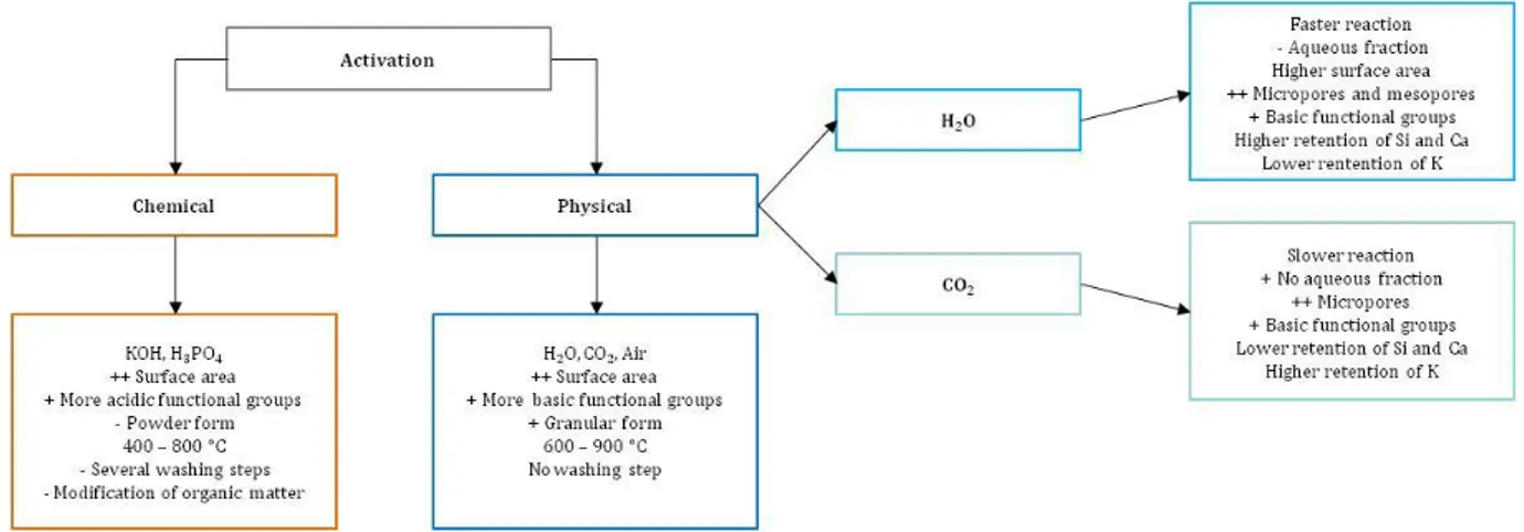
Figure 1-5. Advantages and disadvantages of chemical, physical, steam and CO2 activation processes. ... 38
Figure 1-6. Applications of biogas. ... 53
Figure 2-1. Experimental configuration of pyrolysis and activation pilot. ... 66
Figure 2-2. Temperature profile of pyrolysis. ... 67
Figure 2-3. Description of two-step activation. ... 69
Figure 2-4. Description of one-step or direct activation with CO2. ... 70
Figure 2-5. Description of one-step or direct activation with steam. ... 71
Figure 2-6. Analytical methods applied to each material in order to study its properties. . 72
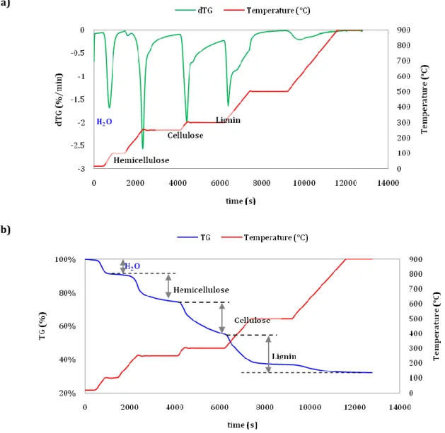
Figure 2-7. Determination of hemicellulose, cellulose and lignin from TG - dTG curves of buckwheat husks. ... 73
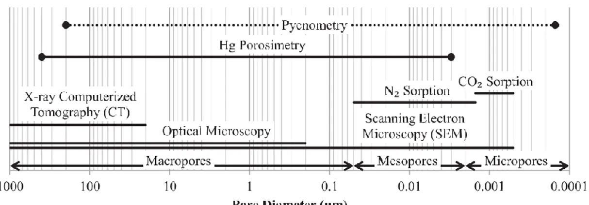
Figure 2-8. Pore size ranges and characterization techniques. Adapted from Brewer et al. [41]. ... 77
Figure 2-9. Types of adsorption isotherms found by nitrogen adsorption-desorption taken from [176]. ... 79
Figure 2-10. Schematic representation of pores types taken from [179]. ... 82
Figure 2-11. Main elements of experimental configuration of syngas and biogas tests. A) and B) Reactor, C) Electrical furnace, D) Gas plate. ... 84
Figure 2-12. Experimental configuration of syngas tests. ... 84
Figure 2-13. Calculation method of performance defined as tar conversion due to presence of chars. ... 87
Figure 2-14. Experimental configuration of biogas tests. ... 89
Figure 2-15. Calculation method of performance defined as adsorption capacity of materials. ... 92
xi
Figure 3-1. TGA analysis curves of BH and MH. ... 96
Figure 3-2. Point of zero charge pH of chars from pyrolysis carried out at 500 °C. ... 99
Figure 3-3. Compressibility of chars during mercury porosimetry analysis: a) BH-Char and b) MH-Char. ... 100
Figure 3-4. SEM image of MH-Char from pyrolysis at 500 °C. ... 101
Figure 3-5. SEM images of chars from pyrolysis: a) BH-Char, b) MH-Char. ... 101
Figure 3-6. Influence of pyrolysis at 500 °C in the geometry of biomass. ... 102
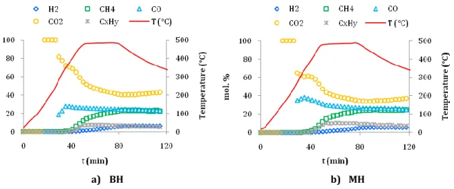
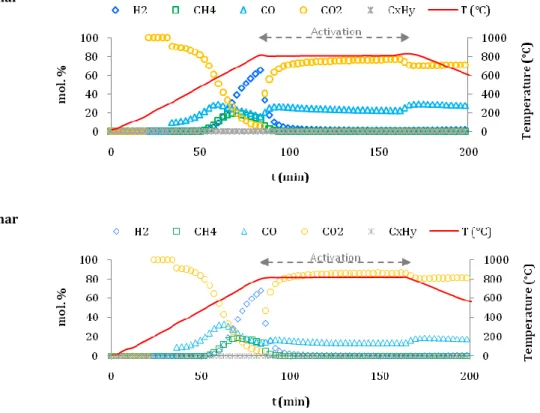
Figure 3-7. Gas composition from pyrolysis of a) BH and b) MH at 500 °C. ... 104
Figure 3-8. Influence of CO2 activation at 850 °C in raw chars. ... 108
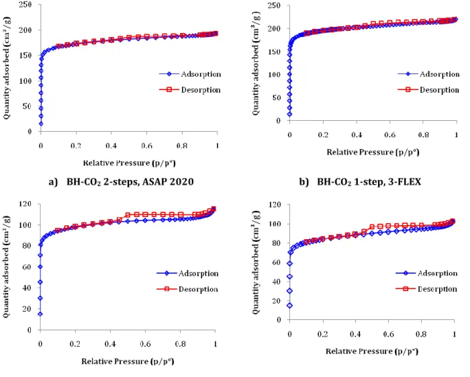
Figure 3-9. N2 Adsorption/Desorption isotherms of a) BH-CO2 2-steps, b) BH-CO2 1-step, c) MH-CO2 2-steps and d) MH-CO2 1-step. ... 111
Figure 3-10. Compressibility of activated chars during mercury porosimetry analysis: a) BH-CO2 and b) MH-CO2. ... 112
Figure 3-11. SEM images of CO2 activated carbons: a) BH-CO2, b) MH-CO2, c) EDX image of MH-CO2. ... 112
Figure 3-12. Limits of mass and energy balances of a) 2-steps and b) 1-step activations.114 Figure 3-13. Gas composition from 2-steps CO2 activation of a) BH-Char and b) MH-Char at 850 °C. ... 116
Figure 3-14. Gas composition from 1-step CO2 activation of a) BH and b) MH at 850 °C. . 116
Figure 3-15. Influence of steam activation at 850 °C in raw chars. ... 120
Figure 3-16. Reactions of Ca(OH)2 and CaCO3 in function of partial pressure of H2O and CO2 adapted from [98]. ... 121
Figure 3-17. N2 adsorption/desorption isotherms of a) BH-H2O and b) MH-H2O. ... 123
Figure 3-18. Compressibility of activated chars during mercury porosimetry analysis: a) BH-H2O and b) MH-H2O. ... 123
Figure 3-19. SEM images of H2O activated carbons: a) BH-H2O, b) MH-H2O. ... 124
Figure 3-20. Relative microporosity and surface area of materials. ... 125
Figure 3-21. Gas composition steam activation of a) BH and b) MH at 850 °C. ... 127
Figure 4-1. Description scheme to differentiate inlet and treated syngas. ... 134
Figure 4-2. Thermal cracking in different syngas matrices at 650 °C, EB = 40 g/Nm3. ... 135
Figure 4-3. Concentration of EB in the outlet stream of the column filled with pyrolysis chars at 650 °C for a simple matrix and a concentration at the inlet of EB = 40 g/Nm3. ... 137
Figure 4-4. Hydrogen released from BH-Char and MH-Char at 650 °C under CO + N2. ... 138
Figure 4-5. Tar composition in simple matrix treated with pyrolysis chars at 650 °C. ... 139
Figure 4-6. Concentration of EB in the outlet stream of the column filled with AC at 650 °C using a simple matrix and inlet concentration of EB of 40 g/Nm3. ... 140
xii Figure 4-7. Weight gain of materials after EB cracking experiments vs performance of
activated carbons in simple matrix at 650 °C. ... 142
Figure 4-8. Tar composition in simple matrix treated with activated carbons at 650 °C. . 144
Figure 4-9. Concentration of EB in the outlet stream of the system at 650 °C using a dry syngas matrix. ... 145
Figure 4-10. Reactivity of calcium oxides at 650 °C in function of partial pressure of CO2 in dry syngas adapted from [98]. ... 146
Figure 4-11. Weight gain of materials after EB cracking experiments vs performance of activated carbons in dry syngas at 650 °C. ... 148
Figure 4-12. Tar composition in dry syngas treated with activated carbons at 650 °C. .... 149
Figure 4-13. Concentration of EB in the outlet stream of the system at 650 °C using a humid syngas matrix. ... 150
Figure 4-14. Comparison of breakthrough curves of a) dry and b) humid syngas at 650 °C and EB = 40 g/Nm3. ... 151
Figure 4-15. Weight gain of materials after EB cracking experiments vs performance of activated carbons in humid syngas at 650 °C. ... 152
Figure 4-16. Tar composition in humid syngas treated with activated carbons at 650 °C. ... 153
Figure 4-17. Comparison of properties of materials for their efficiency in EB cracking at 650 °C for all syngas matrices. ... 155
Figure 4-18. Comparison of fresh and exhausted MH-CO2 and BH-CO2 using SEM, a) and c) fresh samples; b) and d) exhausted samples. ... 157
Figure 4-19. Deactivation rate of materials in different matrices of syngas at 650 °C and EB = 40 g/Nm3, a) MH-CO2, b) MH-H2O, c) BH-CO2, d) BH-H2O. ... 158
Figure 4-20. Tar compounds in produced gas from gasification of exhausted BH-CO2 at 900 °C. ... 159
Figure 5-1. Breakthrough curves of materials at 30 °C in mixture of N2 + H2S. ... 167
Figure 5-2. Adsorption capacity of materials at 30 °C in a mixture of N2 + H2S. ... 168
Figure 5-3. Breakthrough curves of materials at 30 °C in dry biogas. ... 169
Figure 5-4. Adsorption capacity of materials at 30°C in dry biogas. ... 170
Figure 5-5. Breakthrough curves of materials at 30 °C in humid biogas. ... 171
Figure 5-6. Adsorption capacity of materials at 30 °C in humid biogas. ... 172
Figure 5-7. Breakthrough curves of chars at 30 °C in humid biogas. ... 173
Figure 5-8. Influence of porosity distribution in adsorption of H2S from N2 + H2S at 30 °C. ... 174
xiii Figure 5-9. Pore size distribution of steam activated carbons before and after H2S adsorption. ... 176 Figure 5-10. Pore size distribution of CO2 activated carbons before and after H2S adsorption. ... 176 Figure 5-11. Influence of properties of materials in dry conditions... 179 Figure 5-12. Influence of fixed-bed height using BH-CO2 and humid biogas at 30 °C and inlet concentration of H2S of 200 ppm. ... 182 Figure 5-13. Methodology followed for manufacturing bricks from wastes adapted from [205,206]. ... 183 Figure 0-1. Schéma résumé du projet de thèse mettant en évidence les grandes étapes. 228 Figure 6-1. Experimental configuration of syngas treatment pilot. ... 251 Figure 6-2. Calculation method of performance defined as tar conversion due to presence of chars. ... 251 Figure 6-3. Reactions of Ca(OH)2 and CaCO3 in function of partial pressure of H2O and CO2 taken from [37]. In our work: in CO2 activation PCO2 = 0.70 atm; Steam activation PCO2 = 0.085 atm and PH2O = 0.12 atm at 850 °C. ... 252 Figure 6-4. Removal of ethylbenzene due to thermal cracking and materials over time at 650 °C, EB = 40 g/Nm3. ... 252 Figure 6-5. Performance of materials to crack ethylbenzene apart from thermal cracking at 650 °C, EB = 40 g/Nm3. ... 252
1
General introduction
Context of the study
Currently, the world is consuming 99.3 million barrels per day of oil and the demand is expected to increase to 116 million barrels a day by 2030 according to the International Energy Agency [1]. It is agreed that it is necessary to reduce the oil-dependence and to mitigate climate change, thus other alternatives of energy production must be considered. It is well known that a single energy supply method is not sufficient thus combined solutions are required. In that sense, biomass is one of the suitable alternatives to replace fossil fuels since is a carbon-rich material available worldwide. Different thermo-chemical conversion processes are available to convert biomass into energy such as pyrolysis and gasification. Pyrolysis is the thermal decomposition of organic matter in the absence of oxygen that allows obtaining three phases: a combustible gas phase, a liquid phase (oil) and a solid phase (char). Gasification is the process of transforming the solid char and the liquid phase produced by pyrolysis into synthesis gas (syngas) in presence of an oxidizing agent (air, oxygen, steam, carbon dioxide) added in appropriate proportion. Lastly, pyro-gasification is a pyrolysis step followed by a pyro-gasification step and the so-called "gasification" processes are actually pyro-gasification processes in practice, except if they directly gasify coal. Usually in pyro-gasification processes a char phase remains as well. Pyro-gasification is a key process to deal with several major issues worldwide [2]: i) contribute to the future energy supply at an affordable and stable price, ii) deal with the waste generation and pollution, and iii) reduce greenhouse gas emissions.The advantages of pyro-gasification are multiple. It is able to treat wastes that are not directly burned in existing facilities. Most pyro-gasification equipments are able to treat solid wastes with less than 20 % of humidity [3] and some gasifiers can also accept slurry feeds [4]. In addition, this technology is very flexible in terms of the feedstock used (biomass, waste, coal), energy recovery (electricity or biofuel) and capacity (from few kW to several tens MW). Therefore, this diversity is an advantage since it is possible to adapt to the specificities of different local contexts which can contribute to the decentralized energy production. This process is more compact compared to conventional incinerator or boilers, thus this flexibility allows to better fit at local scale. Consequently, this technology is going to grow in the near future as indicated by the Global Syngas Technologies Council [5] which announces that the cumulative worldwide capacity of gasification plants is
2 expected to raise from 150,000 MWth in 2014 to 280,000 MWth in 2018. In addition, the research community is dedicating a lot of effort to the further development and optimization of this technology.
The expected growth of pyro-gasification implies a larger production of char which represents a potential limitation for the development of this process under the principles of circular economy. Currently, resources are taken to manufacture a product which is used and disposed away; this is better known as linear economy. In contrast, the approach of circular economy is to reduce, reuse and recycle. Therefore, fewer amounts of resources are needed, products are manufactured from used materials and after their use they are recycled. In a circular economy, the value of products, materials and resources is preserved in the economy for as long as possible and wastes are minimized. The action plan adopted by the European Commission on 2015 states that the transition to a circular economy requires action in the whole process chain from production to the end life of products involving the creation of markets for waste-derived materials [6]. In addition, the European commission will encourage best practices in the industrial sector and parameters such as durability, upgradability, recyclability will be systematically examined. Consequently, in a circular economy the use of resources involving reuse or various recycling steps should be promoted. For instance, materials from biomass should be reused or recycled several times [7].
According to the report No. 6/2017 of the European Environment Agency, in the circular economy scenario, reuse, redistribution and refurbishment of products have received less attention thus there are no mature strategies in that direction. Most efforts are dedicated to improving the material and energy efficiency, however the inner circles or circular economy such as reuse and recycle have been given less importance. This is a key approach since it limits the waste generation and increases the economy independence of extraction and import of resources. In addition, it has environmental and economic advantages and is recognized as the instrument that allows achieving sustainable growth and development. Therefore closing the loop of products life-cycles by means of reusing and recycling is beneficial for the environment and the economy [8].
Nowadays, chars from pyro-gasification processes are considered residues and don’t have further use, besides the most common application is their implementation as soil conditioners. In Europe, Switzerland is the first country that has officially authorized this use in order to close material cycles [9]. In this regard, the European Biochar Certificate
3 [10] states that char must present carbon content higher than 50 % dry, molar H/C ratio of 0.1 – 0.7 and O/C molar ratio of 0.4. Not all chars can meet these requirements, in particular those with elevated ash content. Besides, there is not a clear trend regarding the impacts of char in soil. For example, some authors have found that the composition of the feedstock and the temperature of pyrolysis determine the phytotoxicity of chars [11]. Moreover, char application rates and frequency remain poorly understood [12]. However, other studies have highlighted the benefits of applying chars in soil such as mitigation of global warming by carbon sequestration and improving soil quality in terms of fertility, pH, soil cation exchange [13].
In line with circular economy, the biorefinery concept should be adopted in order to integrate different technologies and be able to reuse or recycle materials as long as possible. Biorefinery is defined as the sustainable processing of biomass into a spectrum of marketable products and energy according to the IEA Bioenergy Task 42 [14]. In that sense, combined technologies make possible to use the residue from the first process as an input for the second. As happens in an oil refinery, in a biorefinery the raw material is continuously upgraded and refined leading to a cascade of several process [15]. Raw materials for a biorefinery are provided from agriculture, forestry, industries and aquaculture. The products from a biorefinery are material and energy products, the first ones provide energy while the second ones are used for their chemical or physical properties. The most important energy products are gaseous biofuels (biogas, syngas, hydrogen), solid and liquid biofuels. In conclusion, the approach of biorefinery increases the value of biomass as material an energy resource.
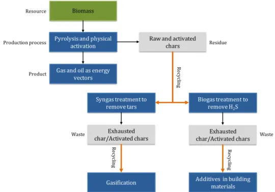
In this project, the principles of circular economy are coupled with the biorefinery concept in order to valorize chars prepared from biomass by thermo-chemical conversion process according to Figure 1-1. Two biomasses are selected and submitted to pyrolysis and physical activation which is assimilated as a pyro-gasification process. In the biorefinery scenario, the raw and activated chars are integrated with other processes such as the syngas and biogas treatment. Then the exhausted chars should be recycled as precursors for gasification or as additives for building materials.
To do so, two wastes from agriculture were selected: buckwheat and millet husks. These wastes have been barely studied in the literature and they can contribute to the development of a circular economy without compromising other well-known alternative valorizations. According to FAO (2016), the total world production of buckwheat is 2.800
4 million tons with a distribution between Europe (510,299 tons), Asia (2,130,344 tons), America (138,113 tons) and Africa (21,325 tons). On the other hand, millet world production is 30,353 million tons concentrated in Asia (16,141 million tons), Africa (13,552 million tons), Europe (332,199 tons), America (291,993 ton) and Australia (36,038 tons). The production of buckwheat and millet grains has experienced an increase of 27 % and 38 % respectively from 2010 to 2016. This increase is explained by the increasing interest in food science given that it contributes to vegan or gluten-free diets.
R ec yc lin g Biomass
Pyrolysis and physical activation
Raw and activated chars
Syngas treatment to
remove tars Biogas treatment to remove H2S
Production process Product R ecy cl in g Exhausted
char/Activated chars char/Activated charsExhausted
Resource
Residue
Additives in building materials
Waste Waste
Gas and oil as energy vectors Gasification R ec yc lin g
Figure 1-1. Schema of the study according to principles of circular economy.
Objective
The objective of this work is to study the possibility of integrating different technologies through the implementation of chars from pyro-gasification in syngas and biogas treatment. In that sense, it is necessary to relate their physical and chemical properties to their efficiency in both applications. This work aims to contribute to the transition to a circular economy by recovering the solid residue of pyro-gasification and using it in other applications. Due to the nature of the initial waste (buckwheat and millet husks) and the different activation methods, resulting materials have very different chemical compositions and physical structures. This variety makes it possible to study the influence of the physical and chemical properties of materials on their purification efficiency. The characterization of materials is carried out in order to obtain a detailed description of their properties (organic composition, mineral species and textural properties). The
5 experiments of syngas and biogas treatment are focused on two main pollutants: tars in syngas and H2S in biogas. Lastly, the exhausted materials must be reuse or recycle in order to avoid waste generation as determined by the principles of circular economy.
This manuscript aims to describe the methodology to achieve the objectives presented above, and to present the main results obtained during these three years of research. This document is composed of five chapters:
Chapter 1 consists of a literature review of the main subjects addressed in this thesis. The purpose of this chapter is to provide a detailed description of chars, methods of production and activation as well as the different alternatives of valorization, with a particular attention paid to their implementation in the syngas and biogas.
Chapter 2 presents the materials and methods used for production and activation of the chars, the characterization of their chemical and textural properties as well as their implementation in syngas and biogas cleaning tests (tar cracking and H2S adsorption). Chapter 3 is dedicated to the preparation and characterization of raw and activated chars. First, the chemical compositions of the materials are exposed. This first step distinguishes two families of materials according to the biomass used. The impact of pyrolysis, CO2 activation and steam activation on the chemical and textural properties is presented. In addition, the mass and energy balances for each process are calculated and different indicators of energy efficiency are proposed.
Chapter 4 presents the purification efficiency of materials in the tar cracking of ethylbenzene. The impact of gas composition is analyzed, and the performance of the materials is compared and related to their physical and chemical properties. The characterization of exhausted samples makes it possible to identify the deactivation mechanism and the nature of the active sites for the cracking reactions of tars. An exploratory study of the life end of exhausted samples is assessed.
Chapter 5 summarizes the main results obtained from hydrogen sulfide removal at room temperature by adsorption on materials. The adsorption capacity of samples is compared and interpreted according to their chemical and textural properties. The impact of the composition of the gas on the H2S adsorption is studied and the involved reaction
6 mechanisms are then discussed. Finally, the ultimate use of samples containing sulfur compounds is proposed.
Introduction
With the aim of integrating different technologies through the recycling of chars from pyro-gasification, multiple topics must be addressed. This first chapter aims to provide the essential information for the understanding of this thesis. The literature review comprises the characteristics of a collection of biomass with different nature which involves organic composition and mineral species that can be found in agricultural wastes. In addition, the different types of pyrolysis are introduced as well as the activation methods that improve the properties of chars from pyrolysis. In the same way, the influence of the oxidizing agent in the activation stage is assessed. Different paths of char valorization are presented paying particular attention to the implementation of syngas and biogas treatment. Accordingly, the composition of syngas and its various pollutants are introduced, and the treatment technologies are presented. Finally, the biogas composition including its several contaminants is described. Likewise, the existing technologies for cleaning biogas are exposed.
1.1. Biomass wastes as char precursor
Biomass is organic matter coming from vegetation and animals and is considered a renewable source of energy. Therefore, biomass is a carbon-rich material found around the world that can potentially contribute to the replacement of fossil fuels. There are several types of biomass such as plant crops, wood, algae and municipal residues. According to the European Commission the biomass is defined as the biodegradable fraction of products, waste and residues from biological origin from agriculture (including vegetal and animal substances), forestry and related industries including fisheries and aquaculture, as well as the biodegradable fraction of industrial and municipal waste (DIRECTIVE 2009/28/EC OF THE EUROPEAN PARLIAMENT AND OF THE COUNCIL of 23 April 2009 on the promotion of the use of energy from renewable sources and amending and subsequently repealing Directives 2001/77/EC and 2003/30/EC).
This work is focused on biomass wastes from plant crops thus; well-known biomasses such as coal or sewage sludge from water treatment plants are excluded. In general, most wastes including biomass residues are disposed in landfills or incinerated. However, biomass wastes are sources of energy that can be recovered through several conversion processes. Conversion
8 technologies are flexible including thermo-chemical processes such as combustion, pyrolysis and gasification whereas biological technologies comprise anaerobic digestion. Availability of biomass wastes from plant crops in France are presented in Table 1-1.
Table 1-1. Crop production in France in 2014 (FAOSTAT).
Crop Production (tons) Crop Production (tons)
Pulses, nes 6 000 Broad beans, horse beans, dry 278 645
Beans, dry 7 500 Sorghum 397 936
Poppy seed 8 000 Oats 443 528
Mustard seed 14 000 Peas, dry 512 094
Lupins 15 020 Pulses 842 259
Oilseeds nes 18 891 Sunflower seed 1 559 100
Lentils 23 000 Maize 1 854 180
Linseed 23 319 Triticale 2 022 500
Olives 23 700 Oilcrops Primary 2 820 272
Millet 40 000 Rapeseed 5 522 980
Hempseed 57 162 Potatoes 8 054 500
Rice, paddy 83 400 Roots and Tubers 8 054 500
Cereals, nes 111 250 Barley 11 770 680
Buckwheat 111 300 Coarse Grain 17 101 227
Rye 128 153 Sugar beet 37 630 688
Grain 221 700 Wheat 38 966 600
Soybeans 227 262 Cereals 56 151 227
Usually, husks and straws remain as wastes after plant crops are processed. Nevertheless, it is important to consider that some of these wastes have already alternative uses and therefore their availability is limited. For example, sunflower and soybean husk are used for animal feeding; oat hulls and oat mill feed are mostly valuable for ruminant and rabbit feeding due to their high fiber content; while rye and barley husks are used for composting.
Figure 1-1. Crop production in France 2014 (potential waste candidates for char production). (FAOSTAT)
9 On the other hand, some of these wastes such as rice husk or hull and corn cobs have been deeply studied in pyrolysis and char production from biomass. Considering these criteria, suitable materials for char preparation available in France reduce to wastes remaining from crop production represented in Figure 1-1. The information provided by the figure shows that wastes from buckwheat and millet crops are available in France and their production is higher compared to other residues.
Biomass composition is defined in terms of cellulose, hemicellulose, lignin and extractives content. A more detailed composition can be given in terms of C, H and O which provide, for most part, its heating value. In general, carbon and oxygen contents of biomass vary in the 40 – 50 % range depending on the origin. However, there are some particular residues such as Cassava peel with higher C (59.3 %) and lower O (28.7 %), contrary to Delorix regia fruit pods with lower C (34.2 %) and higher O (58.9 %) [16]. Biomass also contains small quantities of N, S and Cl. The inorganic part of biomass is composed of Si, Al, Ti, Ca, Mg, Na, K, S, P and other minor elements that are important for its ash characterization. The content of biomass is usually lower than 8 %, nevertheless there are residues with elevated ash content like rice derivates (15 – 17%) [17].
Four references allowed synthesizing the biomass composition for a conglomerate of several agricultural wastes depicted in Table 1-2. The properties of these residues are presented in terms of proximate analysis (moisture, ash, volatiles, fixed carbon), elemental analysis (C, H, N, S, O), cellulose, hemicellulose and lignin contents, as well as higher heating value (HHV).
1.1.1. Moisture content
The moisture content of some agricultural wastes such as sugarcane bagasse, palm fiber and peat is higher than 20 % (Table 1-2), which requires that pyrolysis process is preceded by a drying stage (100–200 °C [18]) in order to eliminate most of the moisture [3]. This step allows less energy consumption during pyrolysis and also limits the water fraction in gas and liquid phases. Thus, it is important to consider this property in order to reduce the energy consumption of the process and maximize the potential value of by-products (gas and bio-oil). In addition, the water content of the bio-oil depends on the initial moisture content of the biomass and water formation during pyrolysis [19]. Therefore, biomass residues with moisture content lower than 20% are preferred in order to minimize the energy demand of the whole process.
10
1.1.2. Cellulose, hemicellulose and lignin content
Biomass chemical composition influences pyrolysis process due to different chemical pathways for cellulose, hemicelluloses and lignin fragmentation [20]. Usually, cellulose is the most abundant component in biomass, accounting for approximately 10 to 45 % as indicated in Table 1-2. In addition, a number of other polysaccharides called hemicelluloses are present in biomass, in the range of 15–35 %. Likewise, lignin is another macromolecular component in biomass, accounting for about 10–30 % weight of the material. Lignocellulosic biomass is also composed by extractives referring to the non-structural components that can be extracted by solvents (e.g., water, ethanol, acetone, benzene and toluene), such as fatty acids, simple sugars, waxes and sterols which account for 0–15 % of the feedstock [19]. According to other authors, cellulose and hemicelluloses determine the amount of carbon oxides produced (CO and CO2) in the gas from pyrolysis, they also contribute to the bio-oil yield, while lignin increases the average molecular weight and viscosity of the bio-oils [19,21]. In addition, lignin favors the char yield thus biomass with high lignin content (> 15%) is preferred to produce chars or activated carbons considering that the higher percentage of fixed carbon is related to higher percentages of lignin [22].
1.1.3. Inorganic composition
Lignocellulosic biomass is known for having inorganic elements such as potassium, magnesium and calcium which are essential nutrients for growth. Major elements present in biomass ash are: Na, K, Ca, Mg, Fe, P, Al and Si [23,24]. Some authors report the inorganic composition as element percentage (Table 1-3) or oxide percentages (Table 1-4) in ashes. The highest contents in ashes, expressed as element or oxides are the Si, K and Ca and in a lesser extent Na and Mg. For example, some biomass ashes are extremely rich in Si: rice and its byproducts contain 90 % of Si, the millet husks have 85 % of Si (or 73 % expressed as SiO2), the bagasse with 61 % of Si and the coconut shells, the palm husks with respectively 69 and 63 % of SiO2. Others are particularly rich in potassium such as the corn cob (43 % as K), the coir pith (39 %), the coconut shell (34 %), the cotton husk (50 % as K2O) and the coffee byproducts (between 37-44 %). Regarding the calcium, the ash from mustard husks exhibit 43 % of CaO and the peat is close to 32 %. The ashes from groundnut shell show respectively 25 % of Ca or CaO. The ashes from subabul wood are the highest concentrated in Ca with 68 %. The ashes from coconut shells are rich in Na (20-22 %) or Na2O (4.8 %) as well as the soya husks with 5 % of Na2O. The magnesium seems particularly present in the ashes from bagasse (22 % of Mg) and from buckwheat husks (17 %), the phosphorus from sunflower husks and pepper waste (9-10% of
11 P2O), the iron from subabul wood (7 % of Fe) and groundnut shells (10 % of Fe2O3), the aluminium from sunflower husks (15 % of Al2O3) and finally the sulfur from mustard husks (14% of sufur as sulphate). According to the provided information, it can be noticed that millet and buckwheat husks have very different inorganic composition.
Some of these elements have demonstrated catalytic effect on the characteristics of pyrolysis products. As others have highlighted, Mg increases the solid content and the presence of high molecular weight compounds in bio-oil which results in higher viscosity [25]. In the same way, Ca decreases the gas yield, decreases the aromatic fraction and acidic compounds and increases polycyclic aromatic hydrocarbons (PAHs) [26]. Other authors have evidenced that release of alkali and alkaline earth metallic (AAEM) species depends on several aspects such as biomass properties, inorganic composition, heating rate and temperature of pyrolysis [27,28]. It seems that pyrolysis at a slow heating rate (10 °C/min) results in minimal (often < 20 %) transformation of AAEM species.
12
Table 1-2. Main characteristics of agricultural wastes. Agricultural
waste
Proximate analysis (wt. %) Ultimate analysis
(wt. %) Cellulose (wt. %) Hemicellulose (wt. %) Lignin (wt. %) HHV (MJ/Kg) Ref Moisture Ash Volatiles Fixed carbon C H N S O
Almond shell 10.0 0.6 80.3 9.1 50.5 6.6 0.2 0.0 42.7 32.5 25.5 24.8 -
[16]
Almond tree pruning 10.6 1.2 72.2 16.0 51.3 6.5 0.8 0.0 41.4 33.7 20.1 25.0 -
Bagasse - 6.2 83.3 - 41.6 5.6 0.0 - 52.9 - - - -
Bamboo 2.4 6.5 69.6 21.4 45.5 4.6 0.2 - - - -
Banana empty fruit bunch 5.2 15.7 78.8 0.2 41.8 5.1 1.2 0.2 51.7 8.3 21.2 19.1 -
Birch 4.4 0.2 - - 48.4 5.6 0.2 - 45.8 - - - -
Cassava peel 11.4 0.3 59.4 28.9 59.3 9.8 2.1 0.1 28.7 - - - -
Cocoa pod husk - - - 42.9 35.3 1.0 -
Coconut shell 8.2 0.1 73.1 18.6 48.6 6.5 0.1 0.1 44.6 19.8 68.7 30.1 -
Corn cob 4.3 0.9 78.7 16.1 46.8 6.0 0.9 - 46.3 - - - -
Delorix regia fruit pods 0.2 2.8 92.0 5.0 34.2 4.5 1.9 0.4 58.9 13.9 24.1 23.4 -
Durian shell 11.3 4.8 - - 39.3 5.9 1.0 0.1 53.7 - - - -
Grape stalk 15.7 10.2 51.1 23.1 46.1 5.7 0.4 0.0 36.6 - - - -
Kola nut pod - - - 38.7 40.4 21.3 -
Olive stone 10.4 1.4 74.4 13.8 44.8 6.0 0.1 0.0 49.1 30.8 17.1 32.6 - Palm shell 8.0 1.1 72.5 18.5 50.0 6.9 1.9 0.0 41.0 29.0 47.7 53.4 - Palm stem 6.1 4.0 72.5 17.5 45.6 5.9 0.8 - 47.7 - - - - Pomegranate seed 5.4 1.8 78.7 14.1 49.7 7.5 4.0 0.7 38.1 27.0 25.5 39.7 - Rice husk - 16.7 65.7 - 36.5 4.8 0.9 - 41.1 - - - - Rice stalk 14.2 14.9 66.3 4.6 40.8 7.7 1.2 0.5 49.9 - - - - Salix 7.3 0.8 - - 48.8 6.2 1.0 - 43.4 - - - - Wallnut shell 11.0 1.3 71.8 15.9 45.1 6.0 0.3 0.0 48.6 40.1 20.7 18.2 - Wheat straw 3.3 3.2 - - 46.5 6.3 0.9 - 46.3 - - - - Woody birch 6.6 0.2 81.2 12.0 48.4 5.6 0.2 - 45.8 - - - - Akhrot shell 8.8 1.2 80.0 18.8 49.8 5.6 0.4 - 42.9 - - - 20.0 [17] Bamboo wood 11.5 2.0 86.8 11.2 48.8 6.3 0.2 - 42.8 - - - 20.5
13
Agricultural waste
Proximate analysis (wt. %) Ultimate analysis
(wt. %) Cellulose (wt. %) Hemicellulose (wt. %) Lignin (wt. %) HHV (MJ/Kg) Ref Moisture Ash Volatiles Fixed carbon C H N S O
Block wood 12.2 2.1 83.3 14.6 46.9 6.1 1.0 - 44.0 - - - 18.3
Casurina wood 12.7 1.8 78.6 19.6 48.5 6.2 0.3 - 43.1 - - - 18.8
Coconut coir pith 19.8 5.2 66.0 28.8 43.4 5.0 1.6 - 44.9 - - - 18.1
Coconut shell 8.3 0.7 77.2 22.1 50.2 5.7 0.0 - 43.4 - - - 20.5
Cotton gin waste 5.0 1.6 83.4 15.0 42.7 6.1 0.2 - 49.5 - - - 17.5
Eucalyptus wood 16.4 3.4 75.4 21.3 46.0 5.8 0.3 - 44.5 - - - 18.6
Groudnut shell 8.1 5.7 72.7 21.6 48.6 5.6 0.6 - 39.5 - - - 19.8
Jawar straw 7.5 8.9 76.0 15.2 42.1 5.6 0.0 - 43.4 - - - 18.0
Jujuba wood 12.5 2.3 83.6 14.1 47.6 6.1 0.2 - 43.8 - - - 19.8
Mango wood 14.1 3.0 85.6 11.4 46.2 6.1 0.3 - 44.4 - - - 19.2
Millet grain waste 5.2 8.4 77.1 14.5 40.6 5.2 0.4 - 45.4 - - - 15.2
Millet straw 5.1 5.3 78.3 16.5 43.7 5.9 0.0 - 45.2 - - - 18.0
Neem wood 12.3 1.9 85.9 12.2 48.3 6.3 0.1 - 43.5 - - - 20.3
Ply wood 13.8 2.1 82.1 15.8 48.1 5.9 1.5 - 42.5 - - - 19.0
Rice husk 8.5 21.2 61.8 17.0 38.5 5.2 0.5 - 34.6 - - - 14.7
Rice husk bran 8.5 18.6 61.8 19.5 38.9 5.1 0.6 - 36.8 - - - 15.3
Rice straw 8.1 20.4 65.7 13.9 35.7 4.6 0.3 - 39.0 - - - 14.9
Subabul wood - dry 7.6 1.2 81.0 18.5 48.2 5.9 0.0 - 44.8 - - - 19.8
Sugarcane bagasse 51.0 3.2 83.7 13.2 45.5 6.0 0.2 - 45.2 - - - 18.7 Wheat straw 8.9 6.9 82.1 11.0 43.0 5.4 0.0 - 44.8 - - - 18.0 Bagasse - 2.9 84.2 - 43.8 5.8 0.4 - 47.1 41.3 22.6 18.3 16.3 [24] Coconut coir - 0.9 82.8 - 47.6 5.7 0.2 - 45.6 47.7 25.9 17.8 14.7 Coconut shell - 0.7 80.2 - 50.2 5.7 0.0 - 43.4 36.3 25.1 28.7 20.5 Coir pit - 7.1 73.3 - 44.0 4.7 0.7 - 43.4 28.6 15.3 31.2 18.1 Corn cob - 2.8 85.4 - 47.6 5.0 0.0 - 44.6 40.3 28.7 16.6 15.7 Corn stalks - 6.8 80.1 - 41.9 5.3 0.0 - 46.0 42.7 23.6 17.5 16.5
14
Agricultural waste
Proximate analysis (wt. %) Ultimate analysis
(wt. %) Cellulose (wt. %) Hemicellulose (wt. %) Lignin (wt. %) HHV (MJ/Kg) Ref Moisture Ash Volatiles Fixed carbon C H N S O
Groundnut shell - 5.9 83.0 - 48.3 5.7 0.8 - 39.4 35.7 18.7 30.2 18.7 Millet husk - 18.1 80.7 - 42.7 6.0 0.1 - 33.0 33.3 26.9 14.0 17.5 Rice husk - 23.5 81.6 - 38.9 5.1 0.6 - 32.0 31.3 24.3 14.3 15.3 Rice straw - 19.8 80.2 - 36.9 5.0 0.4 - 37.9 37.0 22.7 13.6 16.8 Subabul wood - 0.9 85.6 - 48.2 5.9 0.0 - 45.1 39.8 24.0 24.7 19.8 Wheat straw - 11.2 83.9 - 47.5 5.4 0.1 - 35.8 30.5 28.9 16.4 18.0 Sunflower husk 9.1 1.9 69.1 19.9 51.4 5.0 0.6 0.0 43.0 - - - - [29] Cotton husk 6.9 3.2 73.0 16.9 50.4 8.4 1.4 0.0 39.8 - - - - Mustard husk 5.6 3.9 68.6 22.0 46.1 9.2 0.4 0.2 44.7 - - - - Palm fiber 36.4 5.3 46.3 12.0 51.5 6.6 1.5 0.3 40.1 - - - - Pepper waste 9.7 7.4 58.4 24.4 45.7 3.2 3.4 0.6 47.0 - - - - Soya husk 6.3 5.1 69.6 19.0 45.4 6.7 0.9 0.1 46.9 - - - - Groundnut shell 7.9 3.1 68.1 20.9 50.9 7.5 1.2 0.0 40.4 - - - - Coconut shell 4.4 3.1 70.5 22.0 51.2 5.6 0.0 0.1 43.1 - - - -
Coffee (mbuni) husk 11.4 4.1 64.6 20.0 43.9 4.8 1.6 0.1 49.6 - - - -
Coffee (parchment) husk 10.2 0.9 72.0 17.0 46.8 4.9 0.6 0.6 47.1 - - - -
Peat 37.0 4.3 41.0 17.7 57.1 5.9 2.3 0.8 43.1 - - - -
15
Table 1-3. Ash composition of agricultural wastes: mineral elements. Agricultural
wastes
Ash composition of biomass: major elements (wt. %) Ash composition of biomass: trace elements (wt. %)
Ref Al Ca Fe Mg Na K P Si Co Cr Cu Mn Ni S Zn Bagasse - 5.34 0.44 22.03 0.33 9.44 1.00 61.01 - - 0.06 0.03 0.06 0.21 0.06 [24] Coconut coir - 5.55 2.18 6.19 20.45 28.37 0.55 34.79 0.01 0.02 0.79 0.05 0.02 0.74 0.29 Coconut shell 1.28 26.33 2.02 6.82 21.81 34.47 1.65 4.49 0.01 0.01 0.09 0.02 0.23 0.61 0.16 Coir pith 2.48 4.69 1.26 12.16 15.87 39.47 1.76 19.60 0.00 0.00 1.86 0.04 0.03 0.71 0.06 Corn cob - 0.84 0.11 7.78 0.65 43.04 2.05 45.30 - - - 0.09 0.03 0.07 0.05 Corn stalks 5.35 13.11 1.45 16.58 18.09 0.09 5.95 37.50 0.02 0.03 0.09 0.03 0.04 1.58 0.09
Cotton gin waste - 11.80 2.36 15.55 4.10 22.40 2.32 41.05 - 0.02 - 0.12 0.03 0.18 0.07
Groundnut shell 7.13 25.40 2.14 6.95 0.91 34.64 0.54 21.46 0.00 - 0.02 0.09 0.02 0.59 0.10 Millet husk - 3.55 0.58 6.32 0.81 2.19 0.72 85.56 - - - 0.02 0.03 0.18 0.05 Rice husk - 0.76 0.23 0.68 0.06 3.84 0.14 93.62 - - 0.01 0.05 0.01 0.07 0.53 Rice straw - 2.41 0.10 3.18 2.58 2.73 0.38 88.22 - - - 0.23 0.02 0.11 0.02 Subabul wood - 67.54 6.88 13.12 1.03 6.88 1.12 2.19 - - 0.01 0.02 0.01 0.74 0.45 Wheat straw 2.53 7.91 0.14 4.47 8.11 29.86 0.22 45.87 - - 0.01 0.03 0.03 0.81 0.02
16
Table 1-4. Ash composition of agricultural wastes: Oxides.
Agricultural waste Ash composition of biomass wastes: oxides (%wt) Ref
SiO2 Fe2O3 TiO2 P2O5 Al2O3 CaO MgO SO3 Na2O K2O ZnO CuO MnO Na2O
Sunflower husk 17.8 6.4 0.2 9.4 14.5 14.6 8.5 6.8 0.1 21.1 - - - - [29] Cotton husk 10.8 1.9 0.0 4.0 1.3 20.7 7.5 1.7 1.3 49.6 - - - - Coffee husk 3.8 0.2 0.2 4.1 7.5 9.2 ù 0.4 0.6 43.8 - - - - Mustard husk 16.9 0.8 0.1 2.0 1.5 42.8 9.2 14.3 2.0 7.4 - - - - Palm husk 63.2 3.9 0.2 2.8 4.5 - 3.8 2.8 0.8 9.0 - - - - Pepper waste 13.2 2.9 0.1 9.6 7.2 8.6 3.9 9.1 0.9 30.3 - - - - Soya husk 1.7 2.5 0.2 4.9 7.4 21.4 7.1 3.7 5.3 30.5 - - - - Groundnut shell 27.7 10.3 0.1 3.7 8.3 24.8 5.4 10.4 0.8 8.5 - - - - Coconut shell 69.3 6.4 0.0 1.6 8.8 2.5 1.6 0.0 4.8 8.8 - - - -
Coffee (mbuni) husk 13.5 2.2 - 3.7 3.9 10.7 4.0 - 0.4 38.1 - - - -
Coffee (parchment)
husk 16.6 2.4 - 3.4 4.5 9.8 3.7 - 0.5 36.9 - - - -
Peat 24.6 8.2 - 5.4 8.1 31.7 1.2 - 0.4 0.6 - - - -
Millet Husk 73.1 4.2 - 1.6 0.0 10.5 0.0 1.4 - 7.5 - - 0.4 - [30]
Buckwheat Husk 4.0 0.4 - - 0.3 1.0 16.7 - - 22.0 0.1 trace 0.3 0.3 [31]
17
1.2. Char production by thermo-chemical reactions
Char is a solid material formed by the thermo-chemical decomposition of biomass. Chars can be obtained by means of thermo-chemical reactions through several processes such as pyrolysis, gasification and hydrothermal carbonization which are presented below.
1.2.1. Pyrolysis
Pyrolysis is the thermal decomposition of organic matter under inert atmosphere that leads to a solid residue called char, moisture and volatiles of biomass are driven off leading to the formation of liquids (condensable vapors) and gases (non-condensable vapors). More precisely, this decomposition releases most of the non-carbon elements particularly hydrogen, oxygen and nitrogen in the form of gases and tars [16]. The operation also creates rudimentary porosity limited to macropores [32].
Depending on the process conditions, pyrolysis can be divided into six categories, which are shown in Table 1-5.
Table 1-5. Types of pyrolysis [19,33,34]. Type of
pyrolysis Operating condition Reactor types
Liquid (%wt) Gas (%wt) Solid (%wt)
Flash pyrolysis Rapid heating (<0.5s), very small particle sizes (<0.5 mm), temperature (400 - 1000 °C).
Fixed bed reactor, Tubular reactor, Bubbling fluidized bed reactor, Circulating
fluidized bed reactor,
Ablative pyrolyzer, Rotating cones reactor, Auger reactor, Cyclone reactor.
60 - 70 10 -15 15 - 25
Fast pyrolysis
Atmospheric pressure, small particle size (< 3mm), short residence time (0.5 - 2s), moderate temperature (400 - 550 °C) in absence of oxygen.
65 - 75 13 - 25 12 -19
Slow pyrolysis
Low heating rate, moderate temperature (350 - 750 °C), atmospheric pressure, long residence time (5 – 30 min) in absence of oxygen.
30 - 50 15 - 30 30 - 60
Intermediate pyrolysis
Moderate temperature (< 500 °C), moderate vapor residence time (4 - 10s) and atmospheric pressure.
45 - 55 25 - 35 15 - 25 Vacuum
pyrolysis
Moderate temperature (300 - 500 °C), pressure
below atmospheric (< 50KPa). 45 - 60 17 - 27 19 - 27
Ablative pyrolysis
Moderate temperature (450 - 600 °C),
atmospheric pressure, particle size < 3.5 mm. 60 - 80 6 - 10 12 -20
It can be noticed that each type of pyrolysis results in different phase yields. Usually, when the product of interest is the liquid phase fast pyrolysis is used under moderate temperature and very short vapor residence time conditions (0.5-2 s). On the contrary, char is the main product of
18 slow pyrolysis at a slow heating rate (5 – 20 °C/min) [35], longer vapor residence time (5-30 min), and moderate temperature (350-750 °C). At industrial scales, large retorts (batch or continuous), agitated drum kilns, rotary kilns and screw pyrolyzers are used to carry out this process [34].
Operating conditions such as temperature and heating rate influence pyrolysis products. Based on literature, rapid heating and cooling of primary vapor favor high liquid yield, in contrast slow heating leads to a higher char formation considering that secondary pyrolysis reactions are reduced [36,37]. In the same way, higher temperatures result into lower char but higher gas and bio-oil yield because of the stripping of more volatile matter from the char and the increase of secondary cracking reactions of the gas phase [34,38–41]. Temperature not only influences char yield but also the resulting properties of pyrolysis products.
According to Park et al., [39] the lighter fraction of bio-oil composed mostly of water increases with temperature. Likewise, the fraction of H2 and CH4 in the gas phase gradually increases above 400 °C, thus pyrolysis gas at higher temperatures (600 – 700 °C) present higher percentage of H2 and CH4 leading to a superior energetic value of the gas.In fact, in this study the HHV of the gas phase was increased from 4.1 MJ/Kg at 300 °C to 11.5 MJ/Kg at 700 °C. As the yield of pyrolysis products varied with temperature, the energy distribution also did. At 300 °C the energy was distributed as follows: 65 % in the char, 35 % in bio-oil and 3 % in the gas. When temperature was raised to 700 °C, 40 % of energy was contained in the char, 40 % in bio-oil and 28 % in the gas.
1.2.2. Gasification
Gasification is the partial oxidation that transforms organic materials to gaseous products using oxidizing agents (air, oxygen, steam, carbon dioxide). The pyro-gasification is a pyrolysis step followed by a gasification stage and the so-called "gasification" processes are actually pyro-gasification processes in practice, except if they directly gasify char. The desirable product from pyro-gasification process is the gas phase (H2, CO, CO2, N2), however a liquid phase (tars and oil) and a solid phase (char) are also produced. Usually, the yield of char in gasification is lower than pyrolysis (5 – 10 %) [42]. There are different types of gasifiers such as fixed/moving bed, fluidized bed and entrained bed which properties are summarized in Table 1-6.
The fixed bed gasifier also known as moving bed can operate in counter current (updraft) or co-current flow (downdraft) [43,44] while in the entrained bed biomass and gasifying agent are in suspended flow mode. The fixed-bed gasifier presents the largest residence times (15 – 30 min)
19 and the temperature of the outlet gas is in the 400 – 500 °C range. This technology is inexpensive and achieves high carbon conversion however the updraft reactor leads to high tar production while the downdraft requires feed with low ash content limiting its scale up potential.
Table 1-6. Properties of different types of gasifiers [43,45].
Gasifier description Advantages Disadvantages
Fixed/Moving bed Fixed/Moving bed, updraft
Updraft: Gasifying agent is injected at the bottom and fuel is injected at the top Downdraft: gasifying and fuel are injected at the top
Required particle size 2 - 50 mm Gas exit temperature 400 - 500 °C Pressure 0.15 - 2.45 Mpa Residence time 15 - 30 min
Simple, inexpensive process
Operates satisfactorily under pressure High carbon conversion efficiency Low dust levels in gas
High thermal efficiency
Large tar production Potential channeling
Potential bridging, small feed size Potential clinkering
Fixed/Moving bed, downdraft
Simple process
Only traces of tar in product gas
Minimum feed size
Limited ash content allowable in feed Limits to scale up capacity
Potential for bridging and clinkering
Fluidised bed
Fuel and gasifying agent are injected at the bottom or sides
Required average particle size is 8 mm Operation temperature 900 - 1050 °C Residence time 10 – 100 s
Flexible feed rate and composition High ash fuels acceptable Able to pressurize High CH4 in product gas
High volumetric capacity Easy temperature control
Operating temperature limited by ash clinkering
High product gas temperature High tar and fines content in gas Possibility of high C content in fly ash
Circulating fluidised bed
Flexible process
Up to 850 °C operating temperature Corrosion and attrition problems Poor operational control using biomass
Double fluidised bed
Oxygen not required
High CH4 due to low bed temperature
Temperature limit in the oxidizer
More tar due to lower bed temperature Difficult to operate under pressure
Entrained bed
Fuel concurrently react with gasifying agent in suspended (i.e. entrained) flow mode
Require pulverized feedstock, particle size < 1 mm
Operation temperature may exceed 1500 °C
Residence time is in the order of 1 s Pressure 2.94 – 3.43 MPa
Very low in tar and CO2
Flexible to feedstock (accepts both solid and liquid fuels)
Low in CH4
Extreme feedstock size reduction required Complex operational control
Carbon loss with ash Ash slagging
Raw syngas requires significant cooling before being cleaned.
The fluidized bed gasifier operates in the 900 – 1050 °C temperature range with shorter residence times of 10 – 100 s. This technology is able to deal with feedstock with varied composition and high ash content. It can be operated at variable loads (high volume capacity) and the temperature is easily controlled. However, this reactor leads to high tar and particles content and remaining carbon from the feedstock. The entrained bed gasifier requires extreme small solid biomass, but it accept liquid fuels. It operates at very high temperatures and short residence times. This technology presents disadvantages such as the carbon loss with ash, ash slagging and the gas product requires significant cooling.
20 Therefore, the selection of the type of gasifier depends on the type of feedstock (solid, liquid, size and composition), the characteristics of the product gas and the operating limitations related to temperature, pressure and load capacity.
1.2.3. Hydrothermal conversion
Pyrolysis and gasification required limited moisture (<20 %) in the feedstock in order to increase the energy efficiency and fuel conversion. There are several biomass resources that have high moisture content that imposes a drying stage previous to the process to avoid comprising its performance. Hydrothermal conversion is able to overcome this limitation and deals with biomass mixed with water in a close reactor at high pressure. This technology allows the conversion of non-traditional biomass such as: wet animal manures, human waste, sewage sludge, municipal waste, aquaculture and algal residues [46]. Hydrothermal conversion is a cost effective pre-treatment and its advantages are: i) does not require any chemicals, ii) limited equipment corrosion problems, (iii) simple and economical operation [47].
The hydrothermal conversion can be described as follows: at temperature close to 100 °C, the water-soluble portion of the biomass becomes liquid, and above 150 °C hydrolysis takes place. In the meantime, cellulose and hemicellulose, decompose into their monomeric chains. At approximately 200 °C and 1 MPa, solid biomass turns slurry. Finally, at around 300 °C and 10 MPa, liquefaction occurs and the oily product is obtained [48]. Therefore, operating conditions such as temperature and pressure determine the type of hydrothermal conversion of biomass and the distribution of products. Hydrothermal carbonization is carried out in the 180 – 250 °C range of temperature; it operates at pressures up to 20 bar and the processing time varies from 1 to 12 hours.
Hydrothermal process can be classified in three types: carbonization, liquefaction and gasification. In hydrothermal carbonization the main phase is the solid (50 – 80 %) better known as hydrochar, a liquid phase in less proportion (5 – 20 %) and a gas phase (2 – 5 %) [46]. The hydrothermal liquefaction is carried out at temperatures varying between 250 - 400 °C and the desirable product of this process is the oil (40 – 60 %) [49]. Lastly, when hydrothermal conversion is carried out at temperatures above 400 °C it is call hydrothermal gasification whose main product is the gas phase composed of CO, CO2, CH4 and H2[42].
![Figure 1-3. Schematic of oxygen functional groups on the surface of carbons, taken from [78]](https://thumb-eu.123doks.com/thumbv2/123doknet/11624360.304919/50.892.213.681.462.667/figure-schematic-oxygen-functional-groups-surface-carbons-taken.webp)
![Table 1-14. Main impurities of syngas and associated problems adapted from [101,103–108]](https://thumb-eu.123doks.com/thumbv2/123doknet/11624360.304919/57.892.152.745.767.1067/table-main-impurities-syngas-associated-problems-adapted.webp)
![Table 1-16. Tar removal efficiency in various cleaning systems adapted from [103,108]](https://thumb-eu.123doks.com/thumbv2/123doknet/11624360.304919/60.892.95.801.272.518/table-tar-removal-efficiency-various-cleaning-systems-adapted.webp)