HAL Id: hal-01017046
https://hal.archives-ouvertes.fr/hal-01017046
Submitted on 1 Jul 2014
HAL is a multi-disciplinary open access
archive for the deposit and dissemination of
sci-entific research documents, whether they are
pub-lished or not. The documents may come from
teaching and research institutions in France or
abroad, or from public or private research centers.
L’archive ouverte pluridisciplinaire HAL, est
destinée au dépôt et à la diffusion de documents
scientifiques de niveau recherche, publiés ou non,
émanant des établissements d’enseignement et de
recherche français ou étrangers, des laboratoires
publics ou privés.
Frequency analysis of reinforced concrete structures
subjected to accidental impacts
Christophe Rouzaud, Fabrice Gatuingt, Olivier Dorival, Guillaume Hervé,
Nadim Moussallam
To cite this version:
Christophe Rouzaud, Fabrice Gatuingt, Olivier Dorival, Guillaume Hervé, Nadim Moussallam.
Fre-quency analysis of reinforced concrete structures subjected to accidental impacts. 9th International
Conference on Structural Dynamics, Jul 2014, Porto, Portugal. pp.Cle USB. �hal-01017046�
ABSTRACT: The purpose of our study consists in the research of new ways of designing reinforced concrete structures submitted to commercial aircraft impact. We will particularly focus on the shaking resulting from such load case. The cutoff frequency for this type of loading is typically within the to range, which would be refered to as the medium frequency range [1].
The determination of the shaking induced by an aircraft impact on an industrial structure requires dynamic simulation. The response, especially during the transient stage, cannot be completely described using classical finite element method associated with explicit numerical schemes. Indeed, the medium frequency range is often ignored unless the calculation is carried out with a very refined mesh and consequently, a refined time discretization. This could lead to prohibitive computation times.
The linear behaviour is not questioned outside the impact area, however, the non-linearity of the portion of the impacted structure can have a significant influence. The method consists in an initial FFT (Fast Fourier Transform) of the signal loading. The VTCR then ensures an efficient calculation of the response of the structure. The obtained signals are then processed by inverse FFT (IFFT) to reconstruct a time signal and a response spectrum. A new multiscale computational strategy, the Variational Theory of Complex Rays [2], is developed for the analysis of the vibration of structures in the medium frequency regime. Using two-scale shape functions which satisfy the dynamic equation and the constituve relation within each substructure, the VTCR can be viewed as a mean of expressing the power balance at the different interfaces between substructures in a variational form. The solution is searched as a combination of propagative and evanescent waves. Only the amplitude of these waves, which are slowly varying quantities of the solution, is discretized. This leads to a numerical model with few degrees of freedom in comparison with a Finite Element model.
The aim is to develop a robust method to get mid-frequency spectra generated by an aircraft impact on a simplified structure. KEY WORDS: shaking, medium frequency, industrial structure, Variational Theory of Complex Rays (VTCR).
1 INTRODUCTION
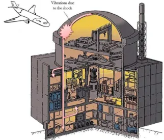
The purpose of our study is to develop new ways for calculating the induced vibrations in reinforced concrete structures submitted to a commercial aircraft impact (see Figure 1). The cutoff frequency for this type of loading is typically within the 40 to 100 Hz range, which would be referred to as the medium frequency range [1].
Taking into account this type of problem and assuming that the structure is appropriately sized to withstand an aircraft impact, the vibrations induced by the shock bring about shaking of the structure. Then the generated waves travel along the containment building, as directly linked with the impact zone, but also in the inner part of the structure due to the connection with the containment building by the raft. The vibrations can therefore induce significant displacements and stresses at the level of equipment and thus the damage caused by bad dimensioning. Our strategy is inscribed in the context of the verification of inner equipment under this kind of shaking. In this type of load case, the impact is a bending problem. This phenomenon induces a non-linear localized area around the impact zone. This area is previously determined through a sensitivity analysis associated with a Taguchi experimental design.
The calculation of the shaking induced by an aircraft impact on an industrial structure requires dynamic studies. The
determination of the response by using classical finite element method associated with explicit numerical schemes requires significant calculation time, especially during the transient stage. This kind of calculation requires several load cases to be analyzed in order to consider a wide range of scenarios. Moreover, the medium frequency range has to be appropriately considered and therefore the mesh has to be very fine, resulting in a refined time discretization.
Figure 1 : Nuclear power plant.
Frequency analysis of reinforced concrete structures subjected to accidental impacts
Christophe Rouzaud1,2,3, Fabrice Gatuingt1, Olivier Dorival1,4, Guillaume Hervé2, Nadim Moussallam31LMT-Cachan, ENS Cachan/UPMC/CNRS/Paris 6 University, 61 avenue du Président Wilson, Cachan 94235, France 2
Université Paris-Est, Institut de Recherche en Constructibilité, ESTP, 28 avenue du Président Wilson, 94230, Cachan, France
3AREVA, 10 rue Juliette Récamier Lyon 69006, France
4Université de Toulouse; Institut Clément Ader (ICA); INSA, UPS, Mines Albi, ISAE 135 av. de Rangueil, 31077 Toulouse
cedex
Email: christophe.rouzaud@ens-cachan.fr, fabrice.gatuingt@ ens-cachan.fr, Olivier.Dorival@isae.fr, gherve@adm.estp.fr, nadim.moussallam@areva.com
2 DESCRIPTION OF THE STRATEGY
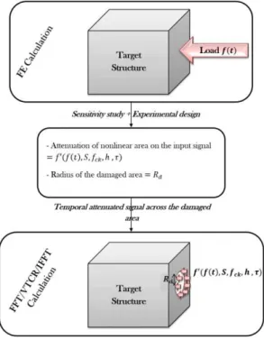
To solve our problem of shock induced vibrations in a reinforced concrete structure the strategy implemented is as follows (see Figure 2). The load is applied on a finite element model of the target structure and its nonlinear response is calculated by finite element method in non-linear case and on a sufficiently short time.
Figure 2 : Global calculation strategy.
The aircraft is replaced by an equivalent force-time function. These data are taken from [3]. The loading diagram can be found using the Riera model [4]. We can present the Riera method as follows: the aircraft impinges perpendicularly on a target considered infinitely rigid and it is assumed that it crashes only at the cross-section next to the target (see Figure 3).
Figure 3 : Model aircraft impacting against a rigid surface. The cross-sectional buckling load decelerates the remaining rigid uncrushed portion. The total impact force is the sum of the buckling load and the force required to decelerate the mass of the impinging cross-section. Since it is a
one-dimensional ideal plastic impact approach, in the model only the buckling load and the distribution of mass are needed. The equation of motion writes:
(1)
where is the mass per unit length of the uncrushed aircraft at impact, the crushed length,
the velocity of
uncrushed portion and the resistance to crushing, i.e. crushing strength.
Equation (1) is used to calculate the current force. The force-time history can thus be determined. A typical force-force-time history, where the impact force and the time function are normalized, is given in Figure 4. In this case, we chose
for the impact velocity and tons for the mass.
Figure 4 : Force as a function of time.
Then the influence of different parameters on the extent of the area of non-linearity is studied. Among these variables, one consider: the thickness of the target ( ), the rate of reinforcement (longitudinal and shear rebars) ( ), the compressive strength of concrete ( ), the loading surface ( ).
The impact of each parameter on the results is also explored through experimental design using the Taguchi methods, as defined in [5]. A sensitivity analysis associated with the experimental design allows us to determine the radius of the damaged area and the attenuation of the nonlinear area on the input signal. The temporal attenuated signal can then be applied at the boundary of the damaged area to obtain the response of the rest of the structure, which behavior remains linear, by a simulation with the VTCR (Variational Theory of Complex Rays). This calculation requires a transformation from time to frequency domain that is achieved by FFT (Fast Fourier Transform). After solving the problem in the frequency domain, a time recomposition is performed by IFFT (Inverse Fast Fourier Transform).
3 DESCRIPTION OF THE VARIATIONAL THEORY OF
COMPLEX RAYS (VTCR)
This work, which uses new computational strategies in dynamics, provides an answer for the steady state of the solution. The problem is solved in the frequency domain. One needs to solve a forced vibration problem over a frequency range which includes the low- and medium-frequency ranges ([6]). The low-frequency and medium-frequency ranges are handled using the Variational Theory of Complex Rays (VTCR) [2].
The reference problem for an assembly of n 3.1
substructures.
We consider the case of homogeneous Kirchhoff-Love’s thin shells which vibrate at a pulsation . The thickness is and the density . Under the assumptions of Kirchhoff-Love, the out-of-plane displacement takes the following form: it is linear in (thickness variable) and a perpendicular to the mean surface stay perpendicular to during the displacement. The displacement of the average surface becomes:
(2)
where is the displacement of the average surface, is the out of plane displacement and the curvature tensor. The average surface of the shell is defined by two independent parameters and . The position of a point on the medium surface is defined by the position vector (see Figure 5).
Figure 5 : Geometry of a shell .
The vector is defined by . The curves
and are the bending lines,
and form a network of orthogonal lines [7]. The base
( ) is then orthogonal. The curvature tensor writes:
[
]( )
(3)
And where and are the radii of curvature of the bending lines.
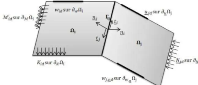
Let shells , with a common border . The actions of the environment are modeled on by imposing displacement on and , rotations on , line stresses on and , and line momentum on . Figure 6 shows the actions of the environment between the field and .
Figure 6 : The reference problem.
The reference problem to be solved is: find such that: Kinematic equations ( ( (4) Where and
The stiffness and damping of the boundary associated with the subdomain and between the subdomains and ([8]) are chosen rigid to simplify our assumptions.
Equilibrium equations on [[ ]] (5) Equilibrium equations on ( ( ∑ ∑ (6) Constitutive relations ( (7)
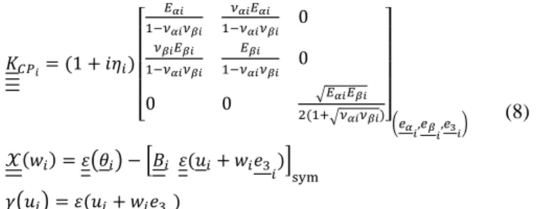
where Hooke’s operator under plane stress assumption, denote densities, denote the structural damping coefficients and operators and are defined as:
[ √ √ ]( ) ( [ ] ( (8)
where the Young’s modulus and the Poisson’s ratio in and direction, the plate’s thickness, the mass density, the frequency, and the damping factor. is the symmetric part of the gradient operator.
The variational formulation associated to the VTCR 3.2
The 1st ingredient of VTCR is a global weak formulation of the boundary conditions in terms of both displacements and forces. The variational formulation can be expressed as: find
such as: (| | ) (| ) (9)
with the following general form:
(| | ) { [∑ ∫ ∑ ∫ ∫ { ∑ ( ∑ ( ∑ ( ∑ ( } ]}(10) (| ) { [∑ ∫ ∑ ∫ ]} (11) where:
the integral part on check on average the imposed displacements on ,
the integral part on satisfy the imposed stresses on ,
the integral part on satisfy the transmission conditions
on the boundary .
designates the real part of a quantity and the conjugate
part. Spaces are the space of admissible fields associated with homogeneous conditions on the structure :
. In our case, .
It is based on a priori independent approximations within the substructures. The constitutive relation (Equation 8) and dynamic equilibrium equation (Equation 10) are exactly satisfied for each substructures to form the corresponding subspace .
It is easy to prove that the variational form is equivalent to the reference problem, provided that:
the reference problem has a solution,
the Hooke’s operator is positive definite,
the damping coefficients are such that ,
The rigid body movements are blocked provided that .
Derivations of two-scale shape functions 3.3
The VTCR uses a two scale approximation of , that exhibits a strong mechanical meaning. The solution is assumed to be properly described locally as the superposition of an infinite number of local vibration modes which can be written in the following manner:
( (
( ( (12)
where both and represent the position vector, (resp. ) being associated with slow variations (resp. to rapid variations). is the complex wave vector associated with the vibration rays in the plane of the shell. In order for these local modes to be admissible, they must be in and satisfy the constitutive and dynamic equilibrium equation. The mechanical waves can be divided into three families (see Figure 7): the P waves (Primary), SH (Secondary Horizontal) and SV (Secondary Vertical) ([9]). We can identify two types of mechanical waves which can describe the membrane effect, the P waves for the pressure effects and the SH waves for shear effects.
Figure 7 : Three families of mechanical waves. 3.3.1 Out-of-plane bending shape functions
For instance, let us consider the out-of-plane bending motions of thin homogeneous shells. According to Kirchhoff’s thin shell theory, the steady-state out-of-plane displacement of the mid-surface of is governed by the following wave equation:
)
( )
By searching the solution of Equation 13 under the wave form Equation 12, one can identify three types of solutions that are related to the shell, the edges of the shell, or the corners of the shell.
A complex interior ray corresponds to a plane bending wave which propagates through the plate in a given direction (see Figure 8).
Figure 8 : Description of interior modes.
Edges and corners modes are evanescent waves. Examples of such modes are shown in Figure 9.
Figure 9 : Interior, edge and corner modes for a homogeneous plate.
3.3.2 The membrane shape functions
Consider the in-plane displacement of a homogeneous thin shell through Kirchhoff-Love model. The rays of vibration must satisfy Equation 8 and Equation 10 to be admissible. The displacement then checks the dynamic equation:
( (14)
The VTCR uses approximations with a high mechanical content. P-waves and SH-waves describes membrane shape functions.
The discretized problem 3.4
The displacement of any point of the substructure is generated by a basis of admissible complex rays. The unknown is the generalized amplitude ( of the basis (an -order polynomial in and a large-wavelength quantity). Accounting for all the directions ⁄ ⁄ and
⁄ in ⁄ ⁄ ⁄ ⁄ leads to an integral over ⁄ ⁄ ⁄ ⁄ .
This integral takes the form:
bending displacement: ( ∫ ( ( ∫ ( ( ∫ ( ( (15)
with , and determined by the dispersion relation from the solution of Equation 13.
membrane displacement: (
∫ (
∫ (
(16)
with and determined by the dispersion relation from the solution of Equation 14.
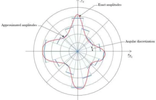
Let us note that admissible space is of infinite dimension since, for instance for interior modes, all directions of propagation are taken into account. To end up with a finite dimension problem that can be solved numerically, one need to discretize into a finite dimension space .
The integral in Equation 15 and Equation 16 can be discretized and one can consider the approximate amplitude
to be constant over each angular sector. The
advantage of this way of doing is that all directions of propagation are still represented in the discretized space, though with an approximation on the amplitude of it (see Figure 10).
Figure 10 : The discretized amplitudes.
The choice of the angular discretization and therefore the number of modes need for solving this kind of problem is related to the number of waves in the structure, on each edges. and to the types of boundary conditions. For example the number of bending waves in the characteristic dimension
⁄ of the shell can be calculated using Equation 43:
√ √ (17) where ⁄ is the wavelength in the direction or , the pulsation, ⁄ √ √ ⁄ the celerity of bending waves, the density, the shell thickness and ⁄ the flexural modulus (for a plate ⁄ ⁄
( ).
The number of wavelength depends on the celerity of the waves: for pressure waves, ⁄ √ ⁄
( and for
shear waves, ⁄ √ √
This discretization is related to several parameters, thus it’s
difficult to define it analytically. Also you can use a "eyes
criterion" to select it. Overall we take a number of rays
between 20 and 100.
4 NUMERICAL EXAMPLE
The VTCR code developed relies on the one developed in [12] for acoustic problems. Adjustments have been made to handle mechanical problems.
First numerical example: one simply supported plate 4.1
In order to study the convergence of the VTCR for plate problems, to validate the associated shape functions and to see the differences with a finite element resolution, let us consider the example [9] given in Figure 11. A simply supported isotropic steel plate with the following mechanical properties is subjected to a point shear loading represented by the red arrow at frequency 2000 Hz:
Young’s modulus = 210 GPa, Poisson’s ratio = 0.3,
mass density = 7800 kg/m3,
damping coefficient= 0.01, thickness of the plate = 0.003 m.
Figure 11 : First example: description of the boundary conditions.
The analytical solution is obtained using the eigenvectors basis of the plate, called . So the analytical out-of-plane displacement is given by:
∑ ∑ (18) where ( ) ( ) (19)
For the exact solution, the infinite sum has to be truncated:
∑ ∑ (20)
Indices and have been chosen with the following assumption: neglected terms have very little influence. We need to take into account √
et
√ .
A reference solution using the finite element code CAST3M [12] was obtained taking around ten linear elements per wavelength for good accuracy. To perform an FE calculation
the element size should depend on the wavelength ([13]). The rule of thumb widely used by engineers [14] consists in taking ten elements per wavelength, but in medium frequency, it is confirmed [15] that an even more refined mesh is required since must remain constant.
VTCR resolution need to add the particular solution (see Equation (22)) corresponding to the solution of an infinite plate subjected to a punctual force to take into account this kind of stress. √ [ √ √ √ ] (21)
where is the distance to and , and the 0th order Bessel functions. The problem is a bending one, thus in this case the membrane vibration modes can be taken to zero. Table 1 shows the out-of-plane displacement obtained with CAST3M, with an analytical solution (see Equation 21) and with the VTCR.
Table 1 : The FE (with Cast3m) solution (left), the analytical solution (middle) and the VTCR solution with dofs
(right). Cast3m Analytical results VTCR 39000 DOFs ( 10 elements/wavelength)
Equation (21) 100 interior modes 4*20 edge modes out -of -plane dis plac ement (m )
One can see that the two solutions are very similar, even though the VTCR was obtained with only 180 DOFs, thanks to its ability to capture analytically the wave phenomena in the rapid scale . One can easily notice the computational efficiency of the VTCR in such a structural vibration problem.
Second numerical example: Civil engineering structure 4.2
In this section the VTCR is used to calculate the medium frequency response of a structure subjected to a sinusoidal loading. We calculate at first the discrete Fourier transform of the load. The VTCR then gives us the frequency response at a chosen point ( ) of the structure specify by the blue cross on Figure 12 for any frequency. The time response is then obtained by the inverse Fourier transform. We therefore consider a concrete structure where the mechanical properties of concrete are calculated according to the rules of Eurocode 2:
concrete B30 =30 MPa, Young’s modulus = 34 GPa, Poisson’s ratio = 0.2, mass density = 2500 kg/m3,
In this study, an hysteretic damping is used. The geometry of the structure is simplified into an assembly of thick plates.
The structure is then subjected to an impact applied at the center of a side wall ( ). This impact produces localized damages on this wall. Here the radius of the non-linearity area is equal to and the temporal attenuated signal in displacement across the damaged area is given by Equation (23). We consider the one-time loading P1 in displacement of the form:
(22)
This loading is modeled by a red arrow in Figure 18. The red and pink lines represent the supports of the structure, respectively, clamped and simple supported.
Figure 12 : Geometry of 3rd numerical example. The computational strategy is as follows. We calculate the discrete Fourier transform of the time load and use it to calculate with the VTCR, the frequency response corresponding to each frequency on a selected point of the structure. The program selects the frequencies having a significant amplitude to describe the good time loading. The time response is then obtained by applying the IFFT to the frequency response.
Figure 13 : displacement applied across the damaged area and the associated Fourier transform.
Two hundred rays are sufficient to properly represent the frequency response. The Table 2 shows the solution obtained in each of four frequencies studied. The boundary conditions are in a good adequacy. This is clearly observable where the load is applied and on the structure supports.
Table 2 : VTCR solution of 3rd numerical example.
Max/per substructures: 102 interior modes, 4*25 edge modes, 50 pressure modes and 50 shear modes 10 Hz 20 Hz out -of -plane dis plac ement (mm ) 30 Hz 40 Hz out -of -plane dis plac ement (mm )
Following the VTCR calculation we can recover the amplitude and the phase of each point of the structure in each frequency and thus reconstruct the time response by IFFT. Then we obtain for the point selected ( ) and designated by a blue cross in Figure 12, the following results (see Figure 14).
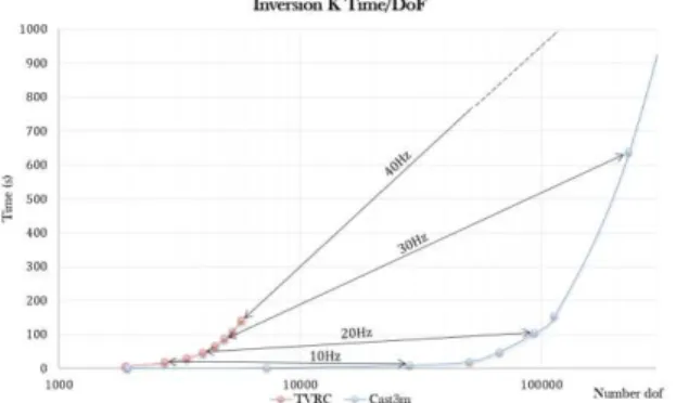
Figure 14 : Displacement amplitude in P2 and the associated inverse Fourier transform, out-of-plane displacement . This study provides us with a very low cost in terms of degrees of freedom used by the VTCR for solving such a problem. Figure 15 shows the difference in CPU time between resolution with VTCR and with CAST3M for this problem. In this figure, the red curve shows different points representing the time required for calculating the solution by increments of
different mesh densities. This density must be thin enough to properly represent the solution.
Figure 15 : Comparison between VTCR and CAST3M in terms of computation time.
5 CONCLUSIONS AND PERSPECTIVES
A new methodology is presented that deals with impact problems and the determination of the shaking induced on this industrial structure. It was illustrated on several examples. A load equivalent to an aircraft impact is applied on a finite element model of the target structure in a non-linear case. So with the non-linear response allows us to determine the radius of the damaged area and the attenuation of the non-linear area on the input signal. We can then apply the temporal attenuated signal at the boundary of the damaged area to obtain the response of the rest of the structure by a simulation with the VTCR. This methodology involves a transformation from time to the frequency domain by FFT. Then a time recomposition is performed by IFFT. Comparisons with finite element calculations provide us with the followings conclusions:
VTCR discretization exhibits a very rich vibrational
content resulting in a very low number of degrees of freedom compared to FEM, at a given frequency,
The FFT-VTCR-IFFT process is an accurate way for
solving the impact problem over a wide time range and a wide frequency range,
The final computation time is far less important than for a
FEM explicit scheme calculation (as soon as the frequency involves medium frequency).
Thanks to the encouraging results obtained for the simple cases presented here, we are able to apply the methodology to the industrial load case of an actual building being impacted by an aircraft. So we need to define the impacted structure. But structures such as nuclear civil engineering may contain floors with a large thickness compared to these dimensions. In this framework we must to study the impact of this thick structures on the response and so if we need to extend the VTCR shapess functions and the VTCR variational formulation to the Reissner-Mindlin's thick shells. An other study must to lead on the large band analysis. Indeed a study one by one frequency can be expensive in computation time. The Proper Generalized Decomposition (PGD) was considered to perform a large band analysis [16]. This method allows to decouple the spatial field to the frequency content and find patterns that can be likened to the eigenmodes of the structure.
REFERENCES
[1] G. Hervé, F. Gatuingt and A. Ibrahimbegovic - On numerical implementation of a coupled rate dependent damage-plasticity constitutive model for concrete in application to high-rate dynamics. Engineering Computations : Int J for Computer-Aided Engineering, 22:583-604. 2005.
[2] Ladevèze P., Arnaud L., Rouch P. and Blanzé C. - The variational theory of complex rays for the calculation of medium-frequency vibrations. Engineering Computations, Vol. 18, pp 193-214. 2001. [3] Bangash M. - Impact and Explosion. Blackwell Scientific Publication.
1993.
[4] Riera J. - A critical reappraisal of nuclear power plant safety against accidental aircraft impact. Nuclear Engineering and Design, 57. 1980. [5] Souvay P. - Les plans d’expériences, Méthode Taguchi. AFNOR. 1994. [6] Ohayon R. and Soize C. - Structural acoustics and vibrations. Academic
Press. 1998.
[7] Laroze S. - Résistance des matériaux et des structures. Tome 1: milieux continus, plaques et coques, Eyrolles, Paris. 1980.
[8] Dorival O., Rouch P. and Allix O. - A substructured Trefftz method for updating joint models in the medium-frequency range. Computational Mechanics, Vol. 42 No. 3, pp 381-394. 2008.
[9] Graff K.F. - Wave motion in elastic solids. Dover New York. 1991. [10] Kovalesky L., Ladevèze P. and Riou H. - The Fourier version of the
Variational Theory of Complex Rays for medium-frequency acoustics. Computer Methods in Applied Mechanics & Engineering, Vol. 225-228, pp 142-153. 2012.
[11] Riou H., Ladevèze P. and Rouch P. - Extension of the variational theory of complex rays to shells for medium-frequency vibrations. J Sound Vib. Vol 272. pp 341-360. 2004.
[12] http://www-cast3m.cea.fr/.
[13] Babuška I., Ihlenburg F., Paik E.T., Sauter S.A. - A generalized finite element method for solving the Helmholtz equation in two dimensions with minimal pollution. Computer Methods in Applied Mechanics and Engineering. pp. 128 : 325-359. 1995.
[14] Deraemaecker A., Babuška I. and Bouillard P. - Dispersion and pollution of the FEM solution for the Helmholtz equation in one, two and three dimensions. Int. J. for Num. Meth. on Engrg., Vol.46, pp.471-499. 1999.
[15] Barbone P.E., Montgomery J.M., Michael O. and Harari I. - Scattering by a hybrid asymptotic/finite element method. Computer Methods in Applied Mechanics and Engineering, Vol.164, pp141-156. 1998. [16] Barbarulo A., Ladevèze P. and Riou H. - A new version of the Proper
Generalized Decomposition applied to acoustical VTCR to obtain predictions over a mid-frequency broad band. Noise and Vibration: Emerging Methods. 2012.