HAL Id: hal-01644893
https://hal.archives-ouvertes.fr/hal-01644893
Submitted on 19 Feb 2018
HAL is a multi-disciplinary open access
archive for the deposit and dissemination of
sci-entific research documents, whether they are
pub-lished or not. The documents may come from
teaching and research institutions in France or
abroad, or from public or private research centers.
L’archive ouverte pluridisciplinaire HAL, est
destinée au dépôt et à la diffusion de documents
scientifiques de niveau recherche, publiés ou non,
émanant des établissements d’enseignement et de
recherche français ou étrangers, des laboratoires
publics ou privés.
The effect of out-of-plane motion on 2D and 3D digital
image correlation measurements
M. A. Sutton, J. H. Yan, V. Tiwari, H. W. Schreier, Jean-José Orteu
To cite this version:
M. A. Sutton, J. H. Yan, V. Tiwari, H. W. Schreier, Jean-José Orteu. The effect of out-of-plane
motion on 2D and 3D digital image correlation measurements. Optics and Lasers in Engineering,
Elsevier, 2008, 46 (10), pp.746-757. �10.1016/j.optlaseng.2008.05.005�. �hal-01644893�
The effect of out-of-plane motion on 2D and 3D digital image
correlation measurements
M.A. Sutton
a,!
, J.H. Yan
a, V. Tiwari
a, H.W. Schreier
b, J.J. Orteu
caDepartment of Mechanical Engineering, University of South Carolina, 300 South Main Street, Columbia, SC 29208, USA b
Correlated Solutions Inc, 109 Kaminer Way, Columbia, SC, USA c
Ecole de Mines D’Albi, Albi, France
Keywords:
Digital image correlation Out-of-plane motion
2D and 3D full-field measurements Displacement
Strain
Camera calibration Image registration
a b s t r a c t
The effect of out of plane motion (including out of plane translation and rotation) on two dimensional (2D) and three dimensional (3D) digital image correlation measurements is demonstrated using basic theoretical pinhole image equations and experimentally through synchronized, multi system measurements. Full field results obtained during rigid body, out of plane motion using a single camera vision system with (a 1) a standard f55mm Nikon lens and (a 2) a single Schneider Kreuznach Xenoplan telecentric lens are compared with data obtained using a two camera stereovision system with standard f55mm Nikon lenses.
Results confirm that the theoretical equations are in excellent agreement with experimental measurements. Specifically, results show that (a) a single camera, 2D imaging system is sensitive to out of plane motion, with in plane strain errors (a 1) due to out of plane translation being proportional toDZ/Z, where Z is the distance from the object to the pin hole and DZ the out of plane translation displacement, and (a 2) due to out of plane rotation are shown to be a function of both rotation angle and the image distance Z; (b) the telecentric lens has an effective object distance, Zeff, that is 50 ! larger
than the 55 mm standard lens, with a corresponding reduction in strain errors from 1250ms/mm of out of plane motion to 25ms/mm; and (c) a stereovision system measures all components of displacement without introducing measurable, full field, strain errors, even though an object may undergo appreciable out of plane translation and rotation.
1. Introduction
Digital image correlation (DIC) generally refers to a class of non contacting methods that acquire images of an object in digital form and perform image analysis to extract sensor plane motions that can be converted into full field measurements on the corresponding object. One of the most commonly used approaches employs random patterns and compares sub regions from ‘‘deformed’’ and ‘‘undeformed’’ images to obtain a full field of sensor plane measurements.
DIC was first conceived and developed in the early 1980s[1 4] for measuring the deformations incurred by a nominally planar object that is subjected to loading resulting in predominantly ‘‘in plane’’ motions. Once the sensor plane motions are deter mined through subset matching, scale factors are used to convert the data into object measurements. The two dimensional (2D) surface strains on the object are extracted using continuum
mechanics principles and estimated gradients in the surface displacement components. Since its inception, the method (designated 2D DIC) has undergone continuous modification and improvement[5 13]. Today, 2D DIC remains an important method for characterizing the mechanical response of homo geneous and heterogeneous materials undergoing nominally planar deformation [14 18], with commercial grade software [10]available to simplify the image analysis component of the measurement process.
As noted previously, 2D DIC theoretically is restricted to (a) planar surfaces, (b) predominantly in plane deformations, and (c) cases where the recording camera can be set perpendi cular to the object surface. In practice, out of plane motions usually are unavoidable. For example, even in a simple tensile experiment, out of plane motions will occur due to factors such as (a) Poisson’s effect, (b) deviations from planarity, (c) small amounts of specimen bending, (d) local necking during the loading process, and (e) deviations from ideal grip constraints, resulting in out of plane rotations and/or translations. In such cases, if a 2D DIC system is employed to determine image dis placement and convert these motions into ‘‘object deformations’’
!Corresponding author. Tel.: +1803 777 7158; fax: +1803 777 0106.
by assuming ideal planar conditions, then the effect of the out of plane motions on the object deformation ‘‘measurements’’ should be understood and, whenever possible, quantified in order to (a) estimate the errors that are embedded in the data and (b) determine whether the embedded errors can be separated and removed from the measurements. Recent work by Haddadi and Belhabib [19]discussed a wide range of factors and their effect on object motion measurements. As part of their study, the authors noted that experimental data indicated (a) a linear relationship between out of plane translation and normal strain1 and (b) a non linear decrease in strain error with increasing image distance, Z. The authors did not include theoretical results for comparison with measurements. Tiwari et al.[20]discussed the effect of translations on strain measurements when using high speed cameras, focusing primarily on planar motions and the effect of image distortions.
In the early 1990s, investigators extended DIC concepts to stereovision systems [21 24]. Designated 3D DIC, a typical stereovision system employs two or more cameras to record digital images of a common object region from two or more viewpoints. Using DIC to perform cross camera subset matching, a calibrated stereovision system theoretically can obtain the true, three dimensional (3D) position of each point on a non planar object. The method has seen remarkable growth in recent years, with applications in aerospace[25,26], micro scale measurements [27], bio materials [28], and fracture mechanics [29 31]. It is important to note that 3D DIC is theoretically capable of extracting accurate, in plane surface deformations, even when the object is undergoing large, three dimensional rigid body rotation and translation.
In this work, the authors have focused on the effects of out of plane motion on 2D DIC and 3D DIC deformation mea surements. After developing the theoretical 2D imaging equations using established pinhole models, the predicted strain errors due to out of plane translations and rotations are presented in Sections 2 and 3, respectively. Section 4 presents details regarding out of plane translation and rotation experiments that were performed so that images are captured simultaneously by both (a) a single camera system (2D DIC) and (b) a two camera stereovision system (3D DIC) to investigate the effect of out of plane motion on 2D DIC and 3D DIC measurements. Section 5 presents results from the experimental studies and Section 6 provides a detailed discussion of the findings. Section 7 presents concluding remarks.
2. Effect of out-of-plane translation on 2D-DIC measurements 2.1. Standard lens systems for single camera measurements
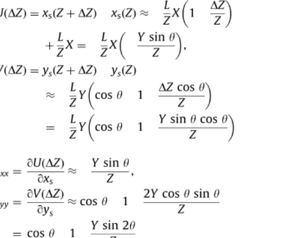
Fig. 1(a) schematically shows the effect of out of plane translation on in plane displacements in the sensor plane for a standard simple lens system. Letting L be the image distance, Z the object distance, and (X, Y) the object in plane dimensions, the in plane image dimensions (xs(Z), ys(Z)) can be determined using established pinhole imaging formulations:
xsðZÞ ¼ L
ZX ¼ MTX; ysðZÞ ¼ L
ZY ¼ MTY (1)
where MT ¼ L/Z is the true, non dimensional initial image plane magnification factor. The image sensor position is defined as (xs, ys) ¼ (XMT, YMT). When the object is translated out of plane byDZ, the image in plane dimensions (xs(Z+DZ), ys(Z+DZ))
are similarly xsðZ þ DZÞ ¼ L Z þ DZX ¼ L Z 1 þDZ Z ! " X & ZLX 1 DZ Z # $ , ysðZ þ DZÞ ¼ L Z þ DZY ¼ L Z 1 þDZ Z ! " Y & ZLY 1 DZ Z # $ (2) where only the first order term in the expansion of (1+(DZ/Z)) 1is retained. The in plane displacement field due to the out of plane translation, DZ, and the resulting strain field can be written as follows: UðDZÞ ¼ xsðZ þ DZÞ xsðZÞ & L ZX DZ Z # $ ¼ xs DZZ # $ , VðDZÞ ¼ ysðZ þ DZÞ ysðZÞ & LZ DZZ # $ Y ¼ ys DZZ # $ (3) !xx¼qUðDZÞ qxs & DZ Z; !yy¼qVðDZÞ qys & DZ Z (4)
DefiningDZ as positive when moving away from the lens, Eq. (4) shows that out of plane translation away from the image plane decreases image magnification and introduces a negative normal strain in all directions.
2.2. Telecentric lens system for single camera measurements For a more complex lens system, such as a combination of elements resulting in an object based telecentric lens, imaging equations (1) and (2) can be employed with some modifications. Specifically, for a telecentric lens, the effect of out of plane motion has been reduced by arranging elements so that light
Fig. 1. Effect of (a) out-of-plane translation and (b) out-of-plane rotation on in-plane displacement fields at the sensor in-plane for a standard single-camera system.
passing through the entrance pupil is nearly parallel to the object axis. In this case, Eq. (4) is modified by replacing physical object distance by an ‘‘effective’’ distance that is many times larger. Thus, for telecentric lenses, the corresponding displacement field has the following approximate form:
UðDZÞ & xsð Z DZ effectiveÞ VðDZÞ & ysð DZ ZeffectiveÞ ) !xx¼ !yy¼ DZ Zeffective (5)
By increasing the ‘‘effective’’ object distance, the recorded image plane displacement field due to out of plane motion will be reduced. Here, the image distance L will be constant in the experimental studies.
3. Effect of out-of-plane rotation on 2D-DIC measurements The effect of out of plane rotation on in plane displace ment fields at the sensor plane for a standard simple lens system is schematically shown inFig. 1(b), where L is the image distance, Z the object distance, (X, Y) the in plane dimen sions of the object,y the rotation angle about the x axis, and DZ the out of plane motion corresponding to the clockwise rotation angley.
Similarly, the in plane displacement field due to out of plane rotation,y(DZ), and the resulting strain field can be written as follows, where only the first order term in the expansion of (1+(DZ/Z)) 1is retained: UðDZÞ ¼ xsðZ þ DZÞ xsðZÞ & L ZX 1 DZ Z # $ þZLX ¼ LZX Ysiny Z # $ , VðDZÞ ¼ ysðZ þ DZÞ ysðZÞ
& LZY cosy 1 DZ cosy Z
# $
¼ LZY cosy 1 Ysiny cos y Z # $ (6) !xx¼ qUðDZÞ qxs & Ysiny Z , !yy¼ qVðDZÞ qys & cos y 1 2Y cosy sin y Z ¼ cos y 1 Ysin 2y Z (7)
Eqs. (6) and (7) show that out of plane rotation with respect to an axis parallel to the horizontal axis of the sensor plane (xs) introduces unequal negative normal strains in xsand ysdirections that are functions of both the rotation angle,y, and offset position from the rotation axis.
4. Experiments
4.1. Out of plane translation and rotation experiments
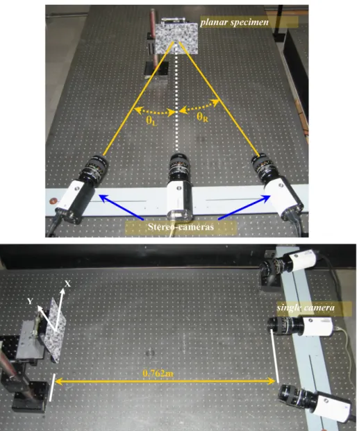
Fig. 2 presents two photographic views of the camera arrangement in the out of plane translation experiments em ployed to simultaneously acquire (a) stereovision images using the two outer cameras and (b) single camera images using the center mounted camera and standard Nikon lens oriented perpendicular to the planar object.Fig. 3shows the single camera
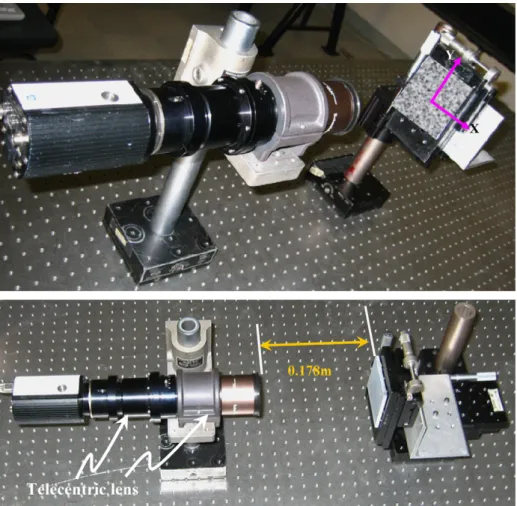
experimental arrangement used to acquire images with a telecentric lens during the out of plane translation. As in the previous experiment, the single camera is oriented perpendicular to the planar object, and the planar object is translated along the optical axis of the single camera.
Fig. 4shows the experimental setup for out of plane rotation with simultaneous (a) stereovision measurements using outer pair of cameras and (b) 2D measurements using the center camera. Initially, the planar object is oriented perpendicular to the optical axis of the center camera. During the rotation experiments, the planar object is rotated about the horizontal X axis shown in Fig. 4.
Table 1 summarizes the vision system parameters used to construct the three optical systems. As shown in Table 1, the true magnification factors are '0.073 and 0.50 for the 2D cameras with standard lens and telecentric lens, respectively. It is noted that a separate experiment setup for out of plane translation was required for the telecentric lens since it has a fixed focal length and a true magnification of 0.50, which made it incompatible with the system geometry shown inFig. 2. Due to this difficulty, the out of plane rotation experiments are per formed on the setup with only standard f55mm lens systems shown inFig. 4.
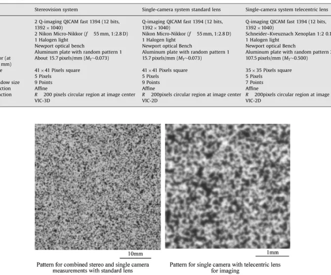
Fig. 5 shows the two random patterns used in this study. The pattern on the left was imaged by the three cameras shown inFigs. 2 and 4, with an in plane scale factor ofE16 pixels/mm. The pattern on the right was imaged by the telecentric lens, which has a fixed true magnification of 0.50 and a scale factor of E108 pixels/mm. The 41 !41 subset size for standard lens systems and 35 ! 35 subset size for telecentric lens system in the analyses were selected to ensure adequate contrast in each subset selected for image matching throughout the region of interest.
4.2. Stereovision calibration
As shown in previous studies [20 31], stereovision systems use multiple camera views to estimate all three components of displacement simultaneously. Hence, the measured 3D dis placement field should be such that the in plane compo nents of displacement are ‘‘independent’’ of the out of plane motion.
Calibration of the stereovision system is performed using 20 images of a translated and rotated planar dot pattern with reasonably well known spacing [20,30,31]. For a stereovision system (stereo rig) calibration, all parameters shown inTable 2 are considered ‘‘intrinsic’’. The parameters shown include:
(
image plane center location, (Cx, Cy), in pixels for each camera;(
the factors (flx, fly) in pixel for each camera, where (lx,ly) are scale factors in the horizontal and vertical directions, respec tively (pixels/mm);(
skew, the deviation from orthogonality between the row and column directions in the sensor plane;(
radial distortion coefficientk1;(
position of pinhole in camera 2 relative to camera 1 (tx, ty, tz) (mm);(
relative orientation of camera 2 with respect to camera 1 (a, b, g) (degrees), where a´ is the relative tilt, b the relative pan angle, andg the swing angle.Inspection of Table 2shows that both the left and the right cameras have an estimated location for the lens center that is shifted by nearly 100 pixels in y direction compared to the geometric center of the sensor plane (696, 520), with a somewhat
higher lens distortion correction coefficient. Though the center location is somewhat anomalous, other parameters, such as the included pan angle between the optical axes of the two cameras, bE371, are in good agreement, with protractor estimate of E381. The relatively small values for the tilt angle, a, and the swing angle,g, are also consistent with visual observations.
It is noted that the distortion factor, k1normalized, represents the contribution of third order radial distortion. The ‘‘normalized’’ version is used to reduce round off error during computations and is defined by the formula k1normalized¼ k1(flx)2 so that corrections in the non dimensional parameter r(flx) 1 at the outer edge of the sensor plane are O(10 2). When converted to pixel units, the corrections at the outer edge of the sensor plane are on the order 0.100 and 0.068 pixels for cameras 1 and 2, respectively.
Though the distortion corrections for cameras 1 and 2 are large near the outer edge, the overall calibration is accurate, with a standard deviation of residuals in the pixel positions for all images of 0.026 and 0.028 pixels for cameras 1 and 2, respectively. The calibration residuals indicate that the calibration is adequate for stereovision measurements, though not as low as seen in previous
experiments, where residuals on the order of 0.012 pixels were obtained.
5. Experimental results 5.1. Out of plane translation
Fig. 6 shows typical horizontal (U) and vertical (V) displace ment fields obtained using (a) a 2D system with standard lens, (b) a 2D system with telecentric lens, and (c) a stereovision system with standard lenses. Since only rigid body out of plane displace ment was applied, the presence of gradientsDU/DxsorDV/Dysin the measured sensor plane displacement fields indicates the potential for strain measurement errors due to out of plane motion. If the gradients are high (low), then the sensitivity of strain measurements to out of plane motion is high (low). Defining W ¼ DZ so that the out of plane displacement toward the camera is positive,Fig. 7presents a line plot for U(X, Y0) for W ¼ 5.5 mm, where Y0corresponds to ys¼ 520 pixels.
Fig. 2. Experimental setup for out-of-plane translation with simultaneous (a) stereovision measurements using outside cameras and (b) two-dimensional measurements using center camera. Specimen was translated and synchronized images were acquired by all cameras.
The measured averageexxand eyy values2 as a function of W for the (a) 2D camera with standard lens, (b) 2D camera with telecentric lens, and (c) stereovision system are shown in Figs. 8 10, respectively.Fig. 11shows the measured strains as a function of W for all three cases. It is important to note that the slope of the linear fit to the measurement data has units of (strain ! 10 6)/mm and represents the amount of strain error per mm of out of plane translation.
It is noted that the standard deviations associated with the measured average strains (exx,eyy) in the region of interest are (a) (100 ! 10 6
, 104 !10 6) for the 2D camera with standard lens, (b) (161 !10 6
, 150 ! 10 6) for the 2D camera with telecentric lens, and (150 ! 10 6
, 115 !10 6) for the stereovision system, representing the spatial variability in the measured normal strain components.
5.2. On out of plane rotation
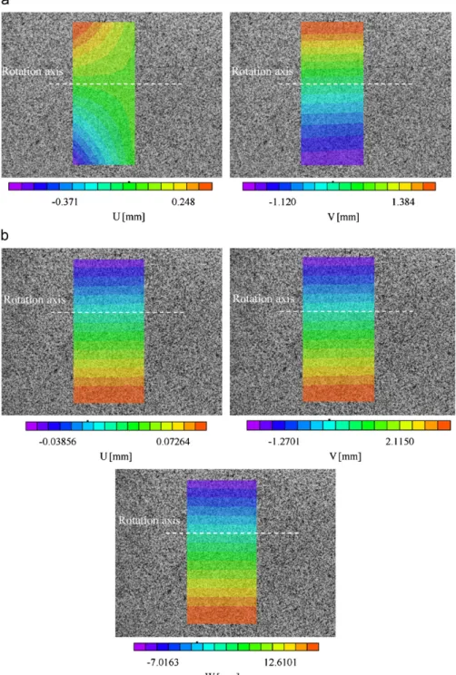
Fig. 12 shows (a) the typical horizontal (U) and vertical (V) displacement fields obtained using a 2D system with standard lens and (b) 3D displacement fields using a stereovision system with standard lenses for an out of plane rotation experiment
Fig. 3. Experimental setup for two-dimensional measurements using single camera with telecentric lens. Specimen was translated out of plane and images were acquired after each motion.
Fig. 4. Experimental setup for out-of-plane rotation with simultaneous (a) stereovision measurements using outside cameras and (b) two-dimensional measurements using center camera. Specimen was rotated and synchronized images were acquired by all cameras.
2
For each out-of-plane motion, the average values are obtained using strain estimates in a region with diameter of 400 pixels and centered at pixel (696, 520).
with rotationyE201. The coordinate system definition is shown in Fig. 4.
Relative to the trends shown in Fig. 12, it should be pointed out that the rotation axis was shifted slightly relative to the vertical centerline (xs0¼ 0 pixel) of the image plane. As a result, the W displacement field shown in Fig. 12(b) is not symmetric relative to the vertical centerline. The estimated position of the rotation axis is shown inFig. 12(b). Defining W ¼ DZ so that the out of plane displacement toward the camera is positive,Fig. 13 presents a line plot for measured W using a 3D stereovision system at different rotation angles, y, where X0 corresponds to xs0¼ 660 pixels.
The 2D DIC values forexxandeyyalong a vertical line (xs0¼ 660 pixels) as a function of distance to the rotation axis for different rotation angles, are shown inFig. 14for a standard lens system. Fig. 15presents typical 3D DIC measuredexxandeyyvalues along a vertical line (xs0¼ 660 pixels) as a function of distance from the rotation axis for yE151; similar results are obtained for all rotation angles.
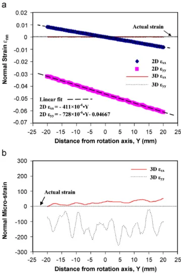
Fig. 16a shows a comparison of measured strains along vertical line (xs0¼ 660 pixels) as a function of distance to the rotation axis at a rotation location E (see Fig. 13) for 2D and 3D DIC systems.Fig. 16b provides details of the strain variations obtained using a 3D DIC system. It is important to note that the slope of the linear fit to the measurement data has units of (strain ! 10 6)/mm and represents the amount of strain error per mm of out of plane motion. With regard to the trends shown in Fig. 16b, the eyy strain measured by the stereovision system is simply the trend along one line; the slight negative strain offset is not the same in all lines with some being shifted to the positive side.
Based on the results shown in Fig. 13 for 3D DIC measure ments, the rotation angley for different rotation positions from A to G can be calculated. Similarly, the rotation angley for different rotation positions from A to G can be obtained from the measured strains using (a) the 2D DIC data shown inFig. 14and (b) the
Table 1
Optical system components
Stereovision system Single-camera system standard lens Single-camera system telecentric lens Cameras 2 Q-imaging QICAM fast 1394 (12 bits,
1392 ! 1040)
Q-imaging QICAM fast 1394 (12 bits, 1392 ! 1040)
Q-imaging QICAM fast 1394 (12 bits, 1392 ! 1040)
Lenses 2 Nikon Micro-Nikkor (f 55 mm, 1:2.8 D) Nikon Micro-Nikkor (f 55 mm, 1:2.8 D) Schneider–Kveuznach Xenoplan 1:2 0.14/11
Lighting 1 Halogen light 1 Halogen light 1 Halogen light
Table Newport optical bench Newport optical Bench Newport optical Bench
Object Aluminum plate with random pattern 1 Aluminum plate with random pattern 1 Aluminum plate with random pattern 2 Scale factor (at
W 0 mm)
About 15.7 pixels/mm (MT'0.073) 15.7 pixels/mm (MT'0.073) 107.5 pixels/mm (MT'0.500)
Subset size 41 !41 Pixels square 41 !41 Pixels square 35 ! 35 Pixels square
Step size 5 Pixels 5 Pixels 5 Pixels
Strain window size 9 Points 9 Points 7 Points
Shape function Affine Affine Affine
Data extraction R 200 pixels circular region at image center R 200pixels circular region at image center R 200pixels circular region at image center
Software VIC-3D VIC-2D VIC-2D
Fig. 5. Random pattern image for (a) combined stereovision and single camera with standard lens (pattern 1) and (b) single camera with telecentric lens (pattern 2).
Table 2
Calibration results for stereovision system
Parameter Camera 1 Camera 2 Camera 1-2 transformation Center x (pixels) 731.9 770.3 Alpha (degrees) )0.45 Center y (pixels) 410.7 417.6 Beta (degrees) +37.79 flx(pixels) 12776.9 12652.3 Gamma (degrees) 10.27
fly(pixels) 12776.9 12652.3 Tx (mm) )525.93
Skew 0 0 Ty (mm) )1.93
k1normalized )0.04846 0.03236 Tz (mm) +184.26
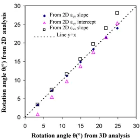
relationship betweenexxandeyyshown in Eq. (7).Fig. 17shows the relationship between the rotation angle obtained from 3D analysis and those from 2D analysis for rotation of the planar target.
6. Discussion
Using Eq (4) and the slope of the best linear fit inFig. 8for the standard lens, the estimated object distance for the 2D system is E0.818 m. This first order estimate is in good agreement with the
physically measured distance ofE0.762 m from the front of the lens to the object.3
Following the same process for the telecentric lens, the data in Fig. 9indicate that the effective object distance isE37.9 m, nearly 50 times larger than measured when imaging with a standard lens. As shown inFig. 9, image defocus occurred for WX5 mm. In
Fig. 6. Typical horizontal and vertical displacement fields obtained using VIC-2D for 2D images and VIC-3D for calibrated stereo pair for out-of-plane displacement toward the camera, W 5.5 mm. (a) Displacement contours, W 5.5 mm for 2D standard lens, (b) Displacement contours, W 5.5 mm for 2D telecentric lens, (c) Displacement contours, W 5.5 mm for 3D standard lenses.
3
Since the object distance used in Eq (4) is measured from the pinhole location (i.e., effective lens ‘‘center’’), the measured distance to the front of the lens is expected to be a lower bound.
Fig. 7. Typical form of measured horizontal displacement, U(X, Y(ys 520 pixels)), along line through image center for W 5.5 mm using all three optical systems. Variability in the measurements is clearly visible in expanded views.
Fig. 8. Measured normal strains using single camera with standard lens and a range of out-of-plane translations. Linear best fit has a slope of 1223me/mm.
Fig. 9. Measured normal strains using single camera with telecentric lens and a range of out-of-plane translations. Linear best fit has a slope of 26.4me/mm.
Fig. 10. Measured normal strains using stereovision system with two standard lenses and a range of out-of-plane translations. Linear best fit toeyyhas a slope approaching zero (1.34me/mm), indicating that out-of-plane translation does not affect the accuracy of the measured, in-plane displacements and strains when using a stereovision system.
Fig. 11. Measured normal strains using all camera systems for out-of-plane translation.
this regime, highly non linear trends were measured with a rapid increase in measured strain. The rapid increase in strain is believed to be primarily due to defocus.4
As shown in the contour plot for stereovision in Fig. 6, the stereovision line plot in Fig. 7and the average strain values in Figs. 10 and 11, a typical stereovision system does not have
discernible displacement gradient in either in plane direction due to out of plane motion. Since a stereovision system simulta neously determines the 3D position before and after experiencing out of plane translation, the data clearly show that the in plane motions measured by a stereovision system are not corrupted by the out of plane displacement component.
Fig. 11 shows that, in comparison to a 2D system using an f55mm lens for imaging, both the 2D system using a telecentric lens for imaging and the stereovision system with standard lenses are insensitive to out of plane motions within the range of focus for each system; the maximum strain errors are, respectively,
Fig. 12. Typical displacement fields obtained using VIC-2D for 2D images and VIC-3D for calibrated stereo pair for rotated target at rotation angle yE201, where U, V, and W are, respectively, horizontal, vertical, and out-of-plane displacements.
4
The measured 2D displacement data obtained from the standard lens and telecentric lens and used to constructFigs. 8 and 9were not corrected for spatial distortion.
E135 me for the telecentric lens at the edge of focus, and E75 me for the stereovision system with standard lenses.
The theoretical prediction of strain error during out of plane translation given in Eq (4) is confirmed by the linear trend ine vs DZ shown inFigs. 7 11. These results clearly show that, once the slope of the linear function is obtained through a set of simple experiments, the effect of out of plane motion on strain accuracy can be predicted.
Previous authors[19]defined an experimental parameter,a, to describe the decrease in strain error that occurs when the object is positioned further from the lens. In this work, theoretical equations clearly show thata is the rational function, 1/Z, a non linear functional form that matches their observations.
As compared with the out of plane translation,Figs. 12,13 and 14 demonstrate that out of plane rotation introduces far more
Fig. 13. Measured out-of-plane displacement by 3D stereovision system versus the distance from the rotation axis at different rotation positions from A to G.
Fig. 14. Measured normal strain by 2D using standard lens versus the distance from the rotation axis at different rotation positions from A to G.
Fig. 15. Typical measured normal strain by 3D stereovision system versus the distance from the rotation axis at rotation position D. Rotation angle isyE151.
Fig. 16. (a) Measured normal strains using both 2D with a standard lens and also a 3D camera systems versus the distance from the rotation axis at rotation position E. (b) Measured normal strain using a 3D stereovision 3D system versus distance from the rotation axis at rotation position at E. Rotation angleyE201.
complex 2D DIC displacement and strain fields. Fortunately, Fig. 17confirms that the theoretical formulae in Eq. (7) accurately describe the strain error components introduced by out of plane rotation.
In contrast to the 2D system results when experiencing out of plane motion, Figs. 15 and 16 once again confirms that a stereovision system with standard lenses is insensitive to out of plane motions within the range of focus, with the maximum strain error less than 300me for the stereovision system with standard lenses.
7. Concluding remarks
A telecentric lens acts very much like a telescope, while retaining high magnification and reasonably good light transmis sion. A well designed telecentric lens also reduces out of plane sensitivity to a manageable level so that out of plane motion will not contribute significantly to in plane strain measurement error. Disadvantages of high quality commercial telecentric lenses are (1) physical size and weight, (2) cost, (3) fixed magnification, and (4) limited depth of focus. The Schneider Xenoplan lens used in these studies was 0.3 m long with a retail cost on the order of $2500 and a 5 mm depth of focus.
The stereovision calibration parameters for both cameras in Table 1indicate a rather large offset of the center location with a corresponding increase in distortion correction. The large number of parameters obtained during the highly non linear calibration process can result in physically unrealistic optimal parameter estimates for a lens camera combination. Even so, the complete set of optimal parameters provides a solution set that will accurately estimate 3D positions for points within the calibration volume. Of course, if one prefers, constrained optimization could be performed, requiring that the center (Cx, Cy) corresponds to the image center. The remaining parameters would then be optimized during the calibration process to obtain a corresponding optimal calibration set that minimizes the error metric.
The combined results in this study indicate that, when using a single camera (2D DIC) to obtain object deformations, relative out of plane motion of the object with respect to the imaging system introduces image plane displacement gradients. If these gradients are large enough, they will corrupt the in plane displacement measurements and make it difficult or impossible
to separate the true deformations for ‘‘pseudo image deforma tions’’ introduced by the rigid body out of plane motion. To minimize the effect of out of plane motion on 2D DIC measure ment, one can increase the distance between the camera and the object when using standard lens according to Eqs. (4) and (7). Another single camera solution is to use a telecentric lens whenever possible.
Another approach suggested by the quality of the data inFig. 17, as well as the demonstrated accuracy of Eqs (4) and (7), is to measure the out of plane displacement at three points on the specimen; dial indicators or laser based range finders are possible options. With this data, it is theoretically possible to estimate the functional form of the strain error for a specific camera system and remove the effects of rigid body, out of plane motion from the measurements.
In practice, out of plane motions are usually not avoidable. For example, most specimens will incur small amounts of out of plane motion during the loading process. Since out of plane translations and rotations are likely to occur simultaneously, in these more complicated cases the best choice seems to be minimizing the error in measurements introduced by out of plane motion. Results confirm that stereovision systems (3D DIC) offer an alternative that simultaneously measures all three components of displacement without introducing in plane dis placement errors.
References
[1] Peters WH, Ranson WF. Digital imaging techniques in experimental stress analysis. Opt Eng 1982;21(3):427–31.
[2] Sutton MA, Wolters WJ, Peters WH, Ranson WF, McNeill SR. Determination of displacements using an improved digital correlation method. Image Vision Comput 1983;1(3):133–9.
[3] He Z-H, Sutton MA, Ranson WF, Peters WH. Two-dimensional fluid velocity measurements by use of digital speckle correlation techniques. Exp Mech 1984;24(2):117–21.
[4] Peters WH, Ranson WF, Sutton MA, Chu TC, Anderson J. Application of digital correlation methods to rigid body mechanics. Opt Eng 1983;22(6):738–42. [5] Chu TC, Ranson WF, Sutton MA. Applications of digital image correlation
techniques to experimental mechanics. Exp Mech 1985;25(3):232–44. [6] Sutton MA, McNeill SR, Jang J, Babai M. Effects of subpixel image restoration
on digital correlation error estimates. Opt Eng 1988;27(10):870–7. [7] Sutton MA, Cheng M, Peters WH, Chao YJ, McNeill SR. Application of an
optimized digital correlation method to planar deformation analysis. Image Vision Comput 1986;4(3):143–50.
[8] Bruck HA, McNeill SR, Sutton MA, Peter WH. Digital image correlation using Newton–Raphson method of partial differential correction. Exp Mech 1989;29(3):261–7.
[9] Sutton MA, Chae TL, Turner JL, Bruck HA. Development of a computer vision methodology for the analysis of surface deformations in magnified images. In: ASTM STP-1094, Proceedings of MICON-90 on advances in video technology for micro-structural evaluation of materials, 1991. p. 109–32. [10] VIC2D and VIC3D. Correlated Solutions Incorporated, 120 Kaminer Way
Parkway Suite, Columbia, SC 29210, USA,/www.correlatedsolutions.comS. [11] Schreier HW, Braasch J, Sutton MA. Systematic errors in digital image
correlation caused by intensity interpolation. Opt Eng 2000;39(11):2915–21. [12] Lu H, Cary PD. Deformation measurements by digital image correlation: implementation of a second-order displacement gradient. Exp Mech 2000; 40(4):393–400.
[13] Schreier HW, Sutton MA. Effect of higher order displacement fields on digital image correlation displacement component estimates. Exp Mech 2002;42(3): 303–11.
[14] Lagattu F, Brillaud J, Lafarie-Frenot MC. High strain gradient measurements by using digital image correlation technique. Mater Charact 2004;53:17–28. [15] Lockwood WD, Tomaz B, Reynolds AP. Mechanical response of friction stir
welded AA2024: experiment and modeling. Mater Sci Eng 2002;A323: 348–53.
[16] Reynolds AP, Duvall F. Digital image correlation for determination of weld and base metal constitutive behavior. Welding J 1999;78(10):355s–60s. [17] Lockwood WD, Reynolds AP. Simulation of the global response of a friction
stir weld using local constitutive behavior. Mater Sci Eng 2003;A339(1–2): 35–42.
[18] Yan J, Sutton MA, Reynolds AP, Samer A, Horsley D. Characterization of heterogeneous response of pipeline steel weld using digital image correlation. In: Proceedings of the 2006 SEM annual conference and exposition on experimental and applied mechanics, June 4–7 2006, St Louis, Missouri, USA, 2006, vol. 1. p. 90–6.
Fig. 17. The relationship between the rotation angle from 3D analysis and those from 2D analysis for the rotation of planar target.
[19] Haddadi H, Belhabib S. Use of rigid-body motion for the investigation and estimation of the measurement errors related to digital image correlation technique. Opt Lasers Eng 2008;46:185–96.
[20] Tiwari V, Sutton MA, McNeill SR. Assessment of high speed imaging systems for 2D and 3D deformation measurements: methodology development and validation. Exp Mech 2007;47(4):561–79.
[21] Luo PF, Chao YJ, Sutton MA. Application of stereo vision to 3-D deformation analysis in fracture experiments. Opt Eng 1994;33(3):981–90.
[22] Luo PF, Chao YJ, Sutton MA, Peters WH. Accurate measurement of three-dimensional deformations in deformable and rigid bodies using computer vision. Exp Mech 1993;33(2):123–32.
[23] Faugeras OD. Three-dimensional computer vision: a geometric viewpoint. Cambridge, MA: MIT Press; 1993.
[24] Helm JD, McNeill SR, Sutton MA. Improved 3-D image correlation for surface displacement measurement. Opt Eng 1996;35(7):1911–20.
[25] Helm JD, Sutton MA, McNeill SR. Deformations in wide, center-notched, thin panels: part I: three dimensional shape and deformation measurements by computer vision. Opt Eng 2003;42(5):1293–305.
[26] Helm JD, Sutton MA, McNeill SR. Deformations in wide, center-notched, thin panels: part II: finite element analysis and comparison to experimental measurements. Opt Eng 2003;42(5):1306–20.
[27] Schreier HW, Garcia D, Sutton MA. Advances in light microscope stereo vision. Exp Mech 2004;44(3):278–88.
[28] Sutton MA, Ke X, Lessner SM, Goldbach M, Yost M, Zhao F, Schreier HW. Strain field measurements on mouse carotid arteries using microscopic three-dimensional digital image correlation. J Biomed Mater Res A 2008;84: 178–90.
[29] Sutton MA, Helm JD, Boone ML. Experimental study of crack growth in thin sheet 2024-T3 aluminum under tension–torsion loading. Int J Fract 2001; 109(3):285–301.
[30] Yan J-H, Sutton MA, Deng X, Cheng C-S. Mixed mode fracture of ductile thin-sheet materials under combined in-plane and out-of-plane loading. Int J Fract 2007;144(4):297–321.
[31] Sutton MA, Yan JH, Deng XM, Cheng C-S, Zavattieri P. 3D digital image correlation to quantify deformation and COD in ductile aluminum under mixed-mode I/III loading. Opt Eng 2007;46(5):051003.