HAL Id: hal-01820068
https://hal.insa-toulouse.fr/hal-01820068
Submitted on 23 Nov 2018
HAL is a multi-disciplinary open access
archive for the deposit and dissemination of sci-entific research documents, whether they are pub-lished or not. The documents may come from teaching and research institutions in France or abroad, or from public or private research centers.
L’archive ouverte pluridisciplinaire HAL, est destinée au dépôt et à la diffusion de documents scientifiques de niveau recherche, publiés ou non, émanant des établissements d’enseignement et de recherche français ou étrangers, des laboratoires publics ou privés.
Chatter in interrupted turning with geometrical defects:
an industrial case study
Sébastien Seguy, Lionel Arnaud, Tamás Insperger
To cite this version:
Sébastien Seguy, Lionel Arnaud, Tamás Insperger. Chatter in interrupted turning with geometri-cal defects: an industrial case study. International Journal of Advanced Manufacturing Technology, Springer Verlag, 2014, 75 (1-4), pp.45-56. �10.1007/s00170-014-6120-0�. �hal-01820068�
CHATTER IN INTERRUPTED TURNING WITH
GEOMETRICAL DEFECTS: AN INDUSTRIAL
CASE STUDY
1*Sébastien SEGUY, 2Lionel ARNAUD, 3Tamás INSPERGER
1Université de Toulouse; INSA; ICA (Institut Clément Ader); 135 avenue de
Rangueil, F-31077 Toulouse cedex 4, France
2Université de Toulouse; ENIT (École Nationale d’Ingénieurs de Tarbes); LGP
(Laboratoire Génie de Production), 47 avenue d’Azereix, BP 1629, F-65016 Tarbes cedex, France
3Department of Applied Mechanics, Budapest University of Technology and
Economics, H-1521 Budapest, Hungary
*Corresponding author. Tel.: +33 05 61 17 11 80 [email protected] (S. SEGUY) L. ARNAUD [email protected] T. INSPERGER [email protected]
Abstract
In this paper, machine tool chatter arising in an interrupted turning process is investigated in a strong industrial context with a complex flexible part. A detailed analysis of the real cutting process is performed with special respect to the geometrical defects of the part in order to highlight the source of machine tool vibrations. The analysis is completed by simple models to estimate the forced vibrations in interrupted turning, the gyroscopic effect, and the mode coupling using a new simplified formulation. Then, a new dynamical model with interrupted cutting and geometrical inaccuracies – runout and orientation of eccentricity – is presented. Stability analysis of this model is performed by the semi-discretization method, an improved technique for analyzing delay-differential equations. The use of all these models on a given machining configuration allows comparing several vibration mechanisms. Thus, behavior’s specificities are highlighted, especially the influence of eccentricity runout on stability. A sensitivity analysis shows the effect of the value and the orientation of the geometrical defects for low speed conditions. Then this result are extrapolated to high-speed conditions to look for possible new stable cutting conditions and shows a period doubling flip instability, never described before in turning operations. The main focus of this paper is developing and exploring a stability model for interrupted cutting in turning with geometrical defects. The complexity of the industrial context led to methodically compare different chatter and vibration mechanisms, this approach can be generalized to other industrial contexts.
Keywords
Interrupted turning, Chatter, Stability, Semi-discretization, Geometrical defects, Industrial context.
CHATTER IN INTERRUPTED TURNING WITH
GEOMETRICAL DEFECTS: AN INDUSTRIAL
CASE STUDY
Abstract
In this paper, machine tool chatter arising in an interrupted turning process is investigated in a strong industrial context with a complex flexible part. A detailed analysis of the real cutting process is performed with special respect to the geometrical defects of the part in order to highlight the source of machine tool vibrations. The analysis is completed by simple models to estimate the forced vibrations in interrupted turning, the gyroscopic effect, and the mode coupling using a new simplified formulation. Then, a new dynamical model with interrupted cutting and geometrical inaccuracies – runout and orientation of eccentricity – is presented. Stability analysis of this model is performed by the semi-discretization method, an improved technique for analyzing delay-differential equations. The use of all these models on a given machining configuration allows comparing several vibration mechanisms. Thus, behavior’s specificities are highlighted, especially the influence of eccentricity runout on stability. A sensitivity analysis shows the effect of the value and the orientation of the geometrical defects for low speed conditions. Then this result are extrapolated to high-speed conditions to look for possible new stable cutting conditions and shows a period doubling flip instability, never described before in turning operations. The main focus of this paper is developing and exploring a stability model for interrupted cutting in turning with geometrical defects. The complexity of the industrial context led to methodically compare different chatter and vibration mechanisms, this approach can be generalized to other industrial contexts.
Keywords
Interrupted turning, Chatter, Stability, Semi-discretization, Geometrical defects, Industrial context.
3B
1. Introduction
The productivity of machining operations is often limited by vibrations. Especially, the self-excited vibration – or chatter – degrades the surface finish of the part, increases the tool wear and reduces the spindle lifespan. However, this phenomenon is not new, already in 1907 F.W. Taylor wrote: “Chatter is the most obscure and delicate of all the problem facing the machinist, and in the case of castings and forgings of miscellaneous shapes probably no rules or formula can be devised which will accurately guide the machinist in taking the maximum cuts and speeds possible without producing chatter” [1]. The chatter is generally
induced by the time delay between two consecutive part revolutions. By the effect of some small external disturbance, the tool start damped oscillation relative to the workpiece, and the surface roughness is undulated. For the next revolution – in turning – the chip thickness is modulated. The equations of motion modeling such mechanism are typically delay-differential equations (DDE). This regenerative mechanism is well known and presented first for turning process [2,3]. Since these works, many researchers have improved the knowledge by the well know stability lobe representation and its adaptation to special cases [4-8].
Several complementary methods to simulate chatter exist in the literature. The most powerful, potentially, are numerical methods using time domain simulation of the equation of motion. These methods may simulate phenomenon at the scale of the cutting tooth, or even at the scale of the tip of the tool, for surface roughness prediction [9]. Methods using finite elements to model the tool-part contact are promising, but remain limited by the complexity of the mechanical models and by the long time simulation for realistic machining operations. Currently, they still do not provide the expected comprehensive approach [10] and simplified model must be used. Thus, since the early 2000's, various approaches based on the analysis of the stability of models using delay-differential equations have been presented [11,12]. These approaches are powerful for the detection of classical Hopf instability, but they can also detect period doubling (also called flip) instability. This last instability is typical for highly interrupted cutting, like for milling with small radial engagement [13]. In particular, the semi-discretization method developed and improved by Insperger and Stépán seems to be a reliable and a powerful technique [14-16], and has been successfully applied to the analysis of different cutting processes [17-21].
The stability of turning process was often modeled by systems to 1 Degree-Of-Freedom (DOF), 2 DOF or 3 DOF mass-spring-dampers. With this modelling, analytical predictions have been developed for orthogonal cutting, to plot stability diagrams [22,23]. Minis et al. [24] used the Nyquist criterion as an alternative approach to obtain the chatter free conditions. However, this approach can be applied only to 1 DOF models. Two DOF models were developed for the case where the workpiece and the tool are flexible [25]. Chandiramani and Pothala [26] presented a 2 DOF model of the cutting tool, which involves the non-linearity when the tool leaves the cut due to large chatter amplitudes. Control of chatter in
case of a 1 DOF model was analyzed in [27]. The turning process is also analyzed by the non-linear dynamics of a state-dependent delay model, in order to mitigate the chatter by Nonlinear Energy Sink [28]. A numerical continuation technique is developed that can be used to follow the periodic orbits of a system with implicitly defined state-dependent delays [29]. Dombovari et al. [30] presented a model of orthogonal cutting to analyze large amplitude motions. The model was formulated as a delay differential equation and included the regenerative effect and the non-linearity when contact between the cutting tool and the workpiece is lost.
Models have been developed for stability analysis of some special cases of boring process in [31,32]. These classical approaches use a 1 or 2 DOF models and derive the classical stability lobe for perfect process, i.e. without geometrical defect and without interrupted cutting. Budak and Ozlu [33] extended the model to a multi-DOF systems. The effects of the three cutting angles, the insert nose radius and the dynamics of the components were included in the cutting system in all directions in a 3 DOF model. The case of interrupted turning was presented theoretically in the work of Szalai and Stépán [34]. Like for milling operations, the highly interrupted turning leads to a period doubling instability for certain parameter combinations. In practice, there are several geometrical defects, which influence the dynamics and sometimes destroy the simple structure of the stability lobes. One of them is the eccentricity where the geometric axis of the turning part differs from the rotation axis. However, this defect was only analyzed for milling process stability [35], and 1-period (or cyclic fold) bifurcation arises including runout [36]. To the best knowledge of the authors [37], relatively little work has been published on interrupted turning, and nothing for turning with flexible workpiece including geometrical defects.
This article focuses on the stability analysis of interrupted turning with geometrical defects where the workpiece is flexible. Various vibration mechanisms are investigated to explain the experimental results: forced vibrations related to interrupted cutting forces, regenerative vibrations related to surface undulation and delay, mode coupling vibrations between two orthogonal eigenmodes and gyroscopic effect for high spindle speed [37]. A new dynamical model is developed to describe the effect of the eccentricity of the workpiece, as the runout effect was clear during experiments. Theoretical stability predictions
are obtained using the semi-discretization method. The article is organized as follows. The industrial context and cutting test analysis are presented in Section 2. The model of interrupted turning with geometrical defects is described in Section 3. Simulation results are discussed in Section 4. Finally the study is concluded in Section 5.
4B
2. Experimental approach
This section presents the experimental approach developed with all the specifications, constrains of mass production and the results obtain in this context. First, the industrial context of experimental analysis is presented, then the modal analysis is conducted, then the geometrical inaccuracies – runout – are analyzed, and finally the stability is investigated with frequency analysis.
10B
2.1. Industrial context
The Ford Aquitaine Industries factory manufactures automatic transmissions for the U.S. market. Automatic transmissions are composed of the following parts: input shaft (connected to the motor), the inverter (clutch), various planetary gearboxes with clutches and brakes associated with different gear ratios, the oil pump (which supplies the pressure for controlling the clutches and brakes), the hydraulic control valve and finally the output shaft which transmits motion to the wheels. The current study deals with the vibrations during the machining of a ring element, which supports a shaft passing through the oil pump. This ring element is made of bronze and serves as a guide, but must also allow oil circulation through its angular sectors (Fig. 1). The manufacturing process is fully automated. The assemblage generates geometrical defects between the support and the ring, therefore the diameter of mounting on the lathe and the diameter of the ring are not exactly concentric. These defects – the value and the orientation of eccentricity – are slightly different for different assemblies due to manufacturing tolerances. The support of the pump is not a body of revolution because of the gear pump. In order to machine the various surfaces, a special mandrel is used to shift the rotation center and to keep equilibrated the system during machining (Fig. 2). The adjustable eccentricity of the mandrel may generate flexibly, increases the overhang part and generate runout on the machine.
In this real industrial problem, all the constraints of mass production are imposed, i.e. limited time for on-site experiments and unavoidable on-site measurement inaccuracies.
11B
2.2. Modal analysis
Before machining, hammer impact tests are made on the following items: ring hollow shaft support, workpiece, tool, spindle. Since the tool is found to be rigid compared to the other elements, its stiffness and frequency response is neglected in the study. The corresponding frequency response functions (FRF) of the workpiece is obtained by a hammer impact tests using an instrumented hammer (2302-10, Endevco), a velocimeter (VH300+, Ometron) and a data acquisition system (Pulse, Brüel & Kjær). It became clear that the hollow shaft is by far the most flexible element, this result is also confirmed by a simplified finite element calculations. Fig. 2 shows the setup of the frequency response measurement. For the hollow shaft, two very close frequencies are find at approximately 1800 Hz along the x axis and 1850 Hz along the y axis, with a stiffness of 15 N/µm and a damping ratio of 0.7%. Since the system is not axisymmetric, the difference between the FRF in different radial directions (e.g. in the x and y directions) can clearly be explained. The modal parameters are collected in Table 1. Finite element analysis of a simplified geometry of the pump support assembly with the hollow shaft and the ring provided a frequency very close to the one obtained by impulse test with accuracy less than 10 Hz. In fact, a simple cantilever beam model also provides the same frequency with accuracy around 50 Hz.
12B
2.3. Geometrical defects analysis
Each assembly contains 3 machined parts. Every day 10 assemblies out of 1200 are scraped due to their non-conformability, moreover the need for visual inspection of all the workpieces also increases the manufacturing costs. The complexity of the manufacturing process is also an important aspect. Each of the 3 workpieces of the assembly is produced through 2 or 3 groups of machining operations, each of them involving 3 or 4 machines tools resulting in about 50 different combinations for each workpiece and thus 50×50×50 possible combinations for the assembled products. Thus systematic analyses of the defects in each operation step on each assembly are practically impossible. An
identification of the numerous factors that are the possible sources of the vibration has been developed [38].
In this study, it is shown that there is no simple correlation between geometrical defects, at various stage of the process, and the vibrations observed. The main geometrical defects are the concentricity and the perpendicularity (Fig. 3), but the combination of these defects does not explain systematically the onset of vibrations.
Moreover, a very detailed study of the manufacturing process over several weeks has shown that operators were able to make some subtle adjustments, improving slightly the quality of the production. Unfortunately it is not possible to determine exact procedures because these adjustments are done below the graduated scales on the machines. For example, such subtle adjustments on tool height and concentricity of the workpiece holder may reduce the scrap ratio below 1% for a while, but unfortunately it was almost impossible to reduce the average scrap ratio to less than 1%.
Comparison to another similar machining processes in the factory, not subjected to vibrations, has shown that stiffness of the workpiece-tool-machine system is probably also an important factor, but again it does not explain the occurrence of the vibrations alone.
Finally, because this machining process is at very high level of production, it is not realistic to consider major modifications of the process to reduce the vibration, because the cost associated would be too high. Practically, a preliminary study shown that a small adjustment on the cutting angle resulted in a major improvement of the scrap ratio even if the real source of the problem has not been clearly identified at this stage [38]. The aim of this paper is to try to go further in the analysis of the phenomenon.
13B
2.4. Stability problem and frequency analysis
The spindle speed is 2200 rpm (Vc = 131 m/min), radial engagement during semi-finishing is 0.12 mm, during semi-finishing is 0.05 mm. At the beginning, the process was designed for a single-step finishing with 0.17 mm radial pass, but because of vibrations it has never been possible and semi-finishing has been introduced. The lead angle of the tool is = 95°, the axial and the radial cutting angles are
-8°, respectively, the nose radius is r = 0.8 mm, diamond insert PC50 is
used with no lubrication (dry machining).
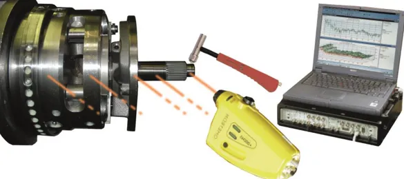
The optical analysis of the vibrations on the machined surface allows approximating the associated frequencies (Fig. 4). By measuring the number of vibration marks on one of the four sectors and by extrapolation over the non-machined sectors, one can count around 50 marks per revolution. Considering that the workpiece spindle speed is 2200 rpm this marks corresponds to a frequency of 1833 Hz. The helix associated to these marks is due to the fact that the number of vibration cycles per workpiece revolution is not an integer, thus a phase shift appear during machining and create the helix. Some workpieces showed rapid variations of this helix angle, this demonstrate that dynamic behavior may vary quickly along the machining.
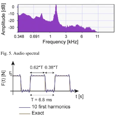
Acoustic measurement during machining showed the same main frequency, around 1850 Hz, illustrated in Fig. 5. During machining the frequency slightly increase but only around 0.2%. The same vibration frequency was measured by a laser velocimeter at the rotating workpiece, and by a piezoelectric accelerometer on the spindle.
3. Model of interrupted turning with geometrical
defects
This section presents the modeling approach developed in order to explain and reduce the vibrations during interrupted turning with geometrical defects. First, the forced vibrations in interrupted turning are estimated by a simple model, then a simple gyroscopic model is presented, after the mode coupling is studied, and finally a new dynamic modeling for interrupted turning is presented.
3.1 Forced vibrations in interrupted turning
First, forced vibrations in interrupted turning are investigated in order to explain the vibration problem. With the cutting parameters and according to the tool manufacturer, the tangential and the radial force components are respectively about 30 N and about 5 N. During the initial development process, cutting forces were estimated at 150 N and 20 N. Due to presence of too frequent vibrations, the finishing was divided in two steps (Section 2.4). It may be noted that a force of 10
N corresponds to a static bending of about 0.7 µm, which is the same order as the amplitude of the machining grooves (of the order of 1 µm).
In interrupted turning, the cutting forces are not constant. In order to show the various harmonics of the main cutting force, the Fourier expansion of a typical interrupted cutting force is considered as an illustration. Only the first 10 harmonics (Fig. 6), are kept, and the following expression was found:
𝐹(𝑡) = 0.62𝐹0[1 + 0.95 𝑐𝑜𝑠 (2𝜋𝑡𝑇 ) − 0.35 𝑐𝑜𝑠 (4𝜋𝑡𝑇 ) − 0.14 𝑐𝑜𝑠 (6𝜋𝑡𝑇 ) + 0.26 𝑐𝑜𝑠 (8𝜋𝑡𝑇 ) − 0.06 𝑐𝑜𝑠 (10𝜋𝑡𝑇 ) − 0.13 𝑐𝑜𝑠 (12𝜋𝑡𝑇 ) + 0.13 𝑐𝑜𝑠 (14𝜋𝑡𝑇 ) +
0.02 𝑐𝑜𝑠 (16𝜋𝑡𝑇 ) − 0.11 𝑐𝑜𝑠 (18𝜋𝑡𝑇 ) + 0.06 𝑐𝑜𝑠 (20𝜋𝑡𝑇 )], (1) where F0 is the mean value of the cutting force.
Compared to experiments, no harmonic of the shock passing frequency (2200 rpm with 4 sector of cut) 146.6 Hz is present from 1800 to 1850 Hz (nearest harmonics are n°12 (a12) and n°13 (a13) at 1760 Hz and 1906 Hz, respectively). In addition,
the coefficients are very low for both harmonics closest (respectively -0.08 and 0.01). Considering the maximum resonance, the forced displacement dmax is expressed as follow:
𝑑𝑚𝑎𝑥 = 𝑎𝑘2𝜉12𝐹 , (2)
with a 10 N radial force, the forced displacement would be 3.8µm. Although resonance effect has the capability to generate the observed defects, we will investigate other vibration mechanisms. First we will naturally investigate gyroscopic effect to try to explain a possible frequency shift that would lead to resonance.
3.2 Gyroscopic effect
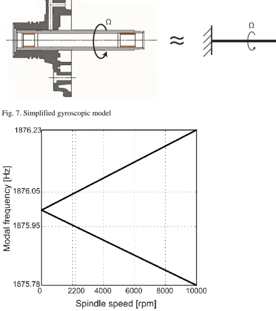
As mentioned is Section 2.2, the system can be modeled by a simple rotating flexible beam of length L as shown in Fig. 7.
The equation of motion for a rotating beam can be classically expressed as follow, including the gyroscopic effects:
[𝑚 0 0 𝑚] { 𝑞̈1 𝑞̈2} + Ω [0 −𝑎𝑎 0 ] { 𝑞̇1 𝑞̇2} + [𝑘 00 𝑘] { 𝑞1 𝑞2} = {00}, (3) where Ω is spindle speed and qi is the modal displacement in the i directions, i.e. transverse to the axis of the cantilever. The mass m is defined by
where 𝜌 is the density, S is the section of the beam and 𝛷(𝑥) is the modal shape. The stiffness k reads
𝑘 = ∫0𝐿12𝐸𝐼𝛷̈(𝑥)2 𝑑𝑥, (5)
where E is the modulus of elasticity and I is the moment of inertia. The coefficient a is
𝑎 = ∫ 2𝜌0𝐿 𝐼Φ̇(𝑥)Φ(𝑥)𝑑𝑥. (6)
The function is classically approximated using the modal shape of first mode of the non-rotating beam.
The classical analytical treatment of the Eq. (3) gives the following two vibrations frequencies: 𝜔1 = √𝜔02+𝑎2𝛺2 2𝑚2 (1 − √1 + 4𝑚2𝜔 02 𝑎2𝛺2 ) , (7) 𝜔2= √𝜔02+𝑎 2𝛺2 2𝑚2 (1 + √1 + 4𝑚2𝜔 0 2 𝑎2𝛺2 ). (8)
The corresponding Campbell diagram can be seen in Fig. 8. As it can be seen, the separation of the dual mode of bending in two modes, by gyroscopic effect is negligible, less than +/- 0.0125% at 10000 rpm.
As a conclusion the gyroscopic effect cannot explain a sufficient shift in frequency to lead to resonance. We will then now study the mode coupling effect, well-known as primary chatter, to try to explain the phenomenon observed.
3.3 Mode coupling effect: primary chatter
The first explanation of the phenomenon of the mode coupling effect was given by Tlusty et al. [3]. Because exact calculation is quite complex we may approximate the magnitude of the phenomenon. Let’s suppose that the movement of the flexible part is elliptical, as described in Fig. 9. During the C to D path energy is dissipated because the movement is against the cutting force. Then during the D to C path energy is gained, and more than what dissipated because the cutting force is greater. At the same time some energy is always dissipated by the damping of the system. Thus vibrations are the result of equilibrium between damping loss and cutting force energy provided during oscillations.
The damping force energy W1 during one cycle is approximated by:
with c the damping, V the average velocity and L the path length of the displacement.
The length of the ellipse is approximated by 𝜋(∆𝑥 + ∆𝑦) and if we consider that the modes are quite orthogonal and with similar amplitudes, the expression of W1 is approximated by:
𝑊1 ≈ 2𝑚𝜉𝜔0𝜋(Δ𝑥+Δ𝑦)2𝜋 𝜔0
𝜋(Δ𝑥 + Δ𝑦). (10)
The cutting force energy W2 during one cycle is expressed by:
𝑊2 = ∮𝑒𝑙𝑙𝑖𝑝𝑠𝑒𝐹𝑥𝑑𝑥 + 𝐹𝑦𝑑𝑦 , (11) with,
𝑥 = ∆𝑥𝑐𝑜𝑠𝜃 ; 𝑦 = ∆𝑦𝑠𝑖𝑛𝜃 ; 𝑑𝑥 = −∆𝑥𝑠𝑖𝑛𝜃𝑑𝜃 ; 𝑑𝑦 = ∆𝑦𝑐𝑜𝑠𝜃𝑑𝜃. (12) If we consider a linear cutting law:
𝐹𝑥= −𝐴𝑝𝐾𝑡(𝑦0+ 𝑦) ; 𝐹𝑦 = −𝐴𝑝𝐾𝑟(𝑦0+ 𝑦). (13) Substituting (12)-(13) in Eq. (11), W2 is expressed by:
𝑊2 = ∫ −𝐴02𝜋 𝑝𝐾𝑡(𝑦0+ ∆𝑦𝑠𝑖𝑛𝜃)(−∆𝑥𝑠𝑖𝑛𝜃)𝑑𝜃 + ∫ −𝐴02𝜋 𝑝𝐾𝑟(𝑦0+
∆𝑦𝑠𝑖𝑛𝜃)∆𝑥𝑐𝑜𝑠𝜃𝑑𝜃. (14)
If we consider that Fy component has a null energy during one cycle and that Fx component is linear with x, W2 is approximated by
𝑊2 ≈ 𝐴𝑝𝐾𝑡∆𝑥∆𝑦 𝜋. (15)
With Ap the length of the cutting edge engaged (along z axis) and Kt the tangential cutting force coefficient (i.e. in x direction).
The equilibrium condition of energy, is
𝑊1 = 𝑊2. (16)
Assuming that ∆𝑥 ≈ ∆𝑦, which is a large simplification of course but ∆𝑥 and ∆𝑦 must anyway be in the same order of magnitude for the coupling effect to take place, so it comes:
2𝑚𝜉𝜔0 2𝜋∆𝑥2𝜋 𝜔0
2𝜋Δ𝑥 ≈ 𝐴𝑝𝐾𝑡∆𝑥∆𝑦 𝜋. (17)
The maximal depth of cut without primary chatter is then: 𝐴𝑝 ≈4𝑚𝜉𝜔0
2
𝐾𝑡 , (18)
with the parameters collected on Table 1 and Table 2, the limit depth of cut is ≈ 1.5 mm. This approximation shows that in our context primary chatter could probably not appear. More over according to [3], the modes coupling may occur
only when the orientation of the lower frequency mode is between the cutting force and the normal of the machined surface. In our context, with a near axisymmetric system, the modes are near x and y axis and the radial cutting force is toward the workpiece, it is thus quite impossible to reach this condition thus to have primary chatter.
3.4 Mechanical model
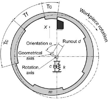
The mechanical model of the turning process is shown in Fig. 10. A preliminary study showed that the gyroscopic effect is negligible (Section 3.2), therefore, the part can be described by a 1 DOF system (Table 1, Section 2.2), in the x direction. The dynamic model is defined by the following equation:
𝑚𝑥(𝑡)̈ + 𝑐𝑥(𝑡)̇ + 𝑘𝑥(𝑡) = 𝐹𝑥(𝑡) , (19)
where m is the modal mass, c is the damping, k is the stiffness, and Fx(t) is the cutting force. The cutting force is expressed by a linear cutting law:
𝐹𝑥(𝑡) = 𝐴𝑝(𝑡)𝐾𝑡𝑔(𝑡)(𝑥(𝑡) − 𝑥(𝑡 − 𝜏)) , (20)
where Ap(t) is the depth of cut, which is time-dependent due to the runout, Kt is the tangential cutting coefficient and is the regenerative time delay:
𝜏 =60Ω , (21)
where Ω is the spindle speed in rpm. Function g(t) is a T-periodic screen function, it is equal to 1 if the tool is cutting, and 0 if the tool is vibrating freely:
𝑔(𝑡) = { 1 if mod (𝑡, 𝑇) ≤ 𝑇𝑐1 0 if mod(𝑡, 𝑇) ≤ 𝑇𝑐1+ 𝑇𝑓1 1 if mod(𝑡, 𝑇) ≤ 𝑇𝑐1+ 𝑇𝑓1+ 𝑇𝑐2 ⋮ 0 if 𝑇 − 𝑇𝑓4 < mod(𝑡, 𝑇) ≤ 𝑇 , (22)
where mod(t,T) denotes the modulo function (e.g. mod(12, 5) = 2), 𝑇𝑐𝑖 and 𝑇𝑓𝑖, 𝑖 = 1,2 … 𝑛 are the periods of cutting and free motions associated to the angular sectors shown in Fig. 10, and 𝑇 = ∑4𝑖=1(𝑇𝑐𝑖+ 𝑇𝑓𝑖) is the rotation period of the workpiece. The scaled values tci and tfi are summarized in Table 2. Note that T is the rotation period, which is equal to the regenerative delay .
The eccentricity is described by two parameters: d is the absolute value of the runout and is the orientation angle of the runout compared to the onset of the machined segments. The actual time-dependent depth of cut can be expressed as: 𝐴𝑝(𝑡) = 𝐴𝑝,𝑖𝑑− 𝑑 𝑐𝑜𝑠 (𝛺2𝜋60 𝑡 − 𝛼), (23)
where 𝐴𝑝,𝑖𝑑 is the axial depth of cut in the ideal case without any eccentricity. This new mechanical model contains all the parameter for analysis of stability in interrupted turning process with geometrical inaccuracies, i.e. runout and orientation of eccentricity.
4. Theoretical stability predictions
This section presents the theoretical predictions. First, the semi-discretization method is presented and the specifications are highlighted. Then the stability study is conducted in the case of real industrial case, and finally the results are extrapolated to the high-speed domain to high light the appearance of flip lobes, in turning, which is new.
4.1 Semi-discretization method
The semi-discretization method is presented according to [15], it’s a well-known method, validated in many configurations machining [16]. Eqs. (19) and (20) imply: 𝐱̇(𝑡) = 𝐀(𝑡)𝐱(𝑡) + 𝐁(𝑡)𝑢(𝑡 − 𝜏), (24) 𝑢(𝑡) = 𝐂𝐱(𝑡), (25) with 𝑥(𝑡) = (𝑥(𝑡)𝑥̇(𝑡)) , 𝐴(𝑡) = (𝐴𝑝(𝑡)𝐾𝑡𝑔(𝑡)0 1 𝑚 − 𝜔0 2 −2𝜁𝜔 0) , 𝐵(𝑡) = ( 0 𝐴𝑝(𝑡)𝐾𝑡𝑔(𝑡) 𝑚 ), 𝐂 = (1 0),
where 𝜔02 = 𝑘/𝑚 is the dominant angular natural frequency of the workpiece and 𝜁 = 𝑐/(2𝑚𝜔0) is the damping ratio. Eqs. (24) and (25) form a delay-differential equation with periodic coefficients. Note that the period of the system is equal to the regenerative delay, i.e., 𝐀(𝑡) = 𝐀(𝑡 + 𝜏) and 𝐁(𝑡) = 𝐁(𝑡 + 𝜏). The stability is analyzed by the first-order semi-discretization method [15,16]. The approximate semi-discrete system for Eq. (24) reads
𝐲̇(𝑡) = 𝐀𝑗𝐲(𝑡) + 𝐁𝑗(𝛽1(𝑡)𝑣(𝑡𝑗−𝑟+1) + 𝛽0(𝑡)𝑣(𝑡𝑗−𝑟)) , 𝑡 ∈ [𝑡𝑗, 𝑡𝑗+1], (26)
𝑣(𝑡) = 𝐂𝐲(𝑡), (27)
where 𝑡𝑗 = 𝑗Δ𝑡, Δ𝑡 = 𝜏/𝑛 is the discretization step, n is an integer approximation parameter and
𝐀𝑗 = 𝟏 Δ𝑡∫ 𝐀(𝑡)d𝑡, 𝑡𝑗+1 𝑡𝑗 𝐁𝑗 = 𝟏 Δ𝑡∫ 𝐁(𝑡)d𝑡, 𝑡𝑗+1 𝑡𝑗 𝛽1(𝑡) =𝑡 − 𝜏 − (𝑗 − 𝑛)Δ𝑡Δ𝑡 , 𝛽0(𝑡) =𝑡 − 𝜏 − (𝑗 − 𝑛 + 1)Δ𝑡Δ𝑡 .
The system (26)-(27) can be solved as an ODE over the discretization interval [𝑡𝑗, 𝑡𝑗+1] resulting in the discrete map
𝑦(𝑡𝑗+1) = 𝑃𝑗𝑦(𝑡𝑗) + 𝑅𝑗,0𝑣(𝑡𝑗−𝑟) + 𝑅𝑗,1𝑣(𝑡𝑗−𝑟+1), (28) where 𝐏𝑗 = e𝐀𝒋Δ𝑡, 𝐑𝑗,0= − ∫ 𝑠 − 𝜏 + (𝑛 − 1)Δ𝑡 Δ𝑡 e𝐀𝒋(Δ𝑡−𝑠)𝐁𝑗d𝑠 Δ𝑡 0 , 𝐑𝑗,1 = ∫ 𝑠 − 𝜏 + 𝑛Δ𝑡 Δ𝑡 e𝐀𝒋(Δ𝑡−𝑠)𝐁𝑗d𝑠 Δ𝑡 0 . If 𝐀𝑗 is a regular matrix then the above integration gives
𝐑𝑗,0= (𝐀𝑗−1+
1
Δ𝑡(𝐀𝑗−2− (𝜏 − (𝑟 − 1)Δ𝑡)𝐀𝑗−1)(𝐈 − e𝐀𝒋Δ𝑡)) 𝐁𝑗, 𝐑𝑗,1 = (𝐀𝑗−1+ 1
Δ𝑡(−𝐀𝑗−2− (𝜏 − 𝑟Δ𝑡)𝐀𝑗−1)(𝐈 − e𝐀𝒋Δ𝑡)) 𝐁𝑗. Using state-augmentation, the discrete time system can be written as an
𝐳(𝑡𝑗+1) = 𝐆𝑗𝐳(𝑡𝑗), (29) with 𝐳(𝑡𝑗) = 𝑐𝑜𝑙 (𝐲(𝑡𝑗) 𝑣(𝑡𝑗−1) 𝑣(𝑡𝑗−2) … 𝑣(𝑡𝑗−𝑛)) and 𝐆𝑗 = ( 𝐏𝑗 𝐂 0 ⋮ 0 𝟎 0 1 ⋯ 𝟎 ⋯ 0 ⋯ 𝐑𝑗,1 0 0 ⋮ ⋱ ⋮ 0 ⋯ 1 𝐑𝑗,0 0 0 ⋮ 0 ) , (30)
Multiple repeated applications of Eq.(30) with initial state 𝐳(𝑡0) gives the Floquet transition matrix for the semi-discrete system (26)-(27) in the form 𝚽 = 𝐆𝑗𝐆𝑗−1… 𝐆0. Actually, 𝚽 provides a finite dimensional approximation of the
infinite-dimensional monodromy operator of the original system (19)-(20).
The stability of the approximate system (26)-(27) can be assessed by the eigenvalue analysis of matrix 𝚽. If all the eigenvalues are inside the unit circle of the complex plane, then the system (24)-(25) is asymptotically stable. Since semi-discretization preserves asymptotic stability of the original system (19)-(20), the method can be used to construct approximate stability charts.
4.2 Stability analysis in industrial context
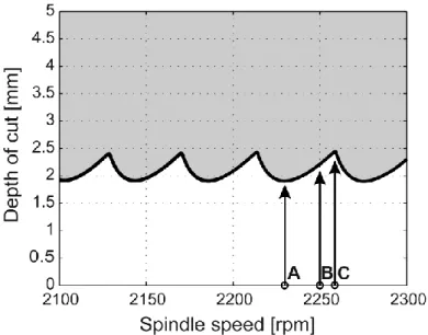
Stability charts are determined for interrupted turning without geometrical defects with the dynamic and cutting coefficient from Table 1 and Table 2. The approximation parameter for the semi-discretization method is r = 300. This parameter was selected in order to have good approximation for lower spindle speeds. The stability lobes – made with a 200×150 grid resolution of the parameter plane – are shown in Figure 11. The unstable, chatter domains are denoted by grey shading.
In this industrial context, the spindle speed of the lathe is limited to 2300 rpm, which is associated with the 50th Hopf lobe. It is not typical in the literature to
encounter regenerative spindle speeds around the 50th Hopf lobe [37]. At these spindle speeds, there are about 20 rpm difference between a maximum and a minimum stable depth of cut, which corresponds to less than 1% of the spindle speed. The vertical position of the optimal area is shifted proportionally to the modal frequency, which may vary from about 0.5% of a workpiece to another. The impacts of geometrical defects (eccentricity and orientation) are now studied through 3D graph representations, on the area of the 50th Hopf lobe. Three characteristic spindle speeds are investigated (Fig. 11):
* 2230 rpm corresponding to the minimal depth of cut (point A), * 2250 rpm corresponding to a medium depth of cut (point B), * 2259 rpm corresponding to the maximal depth of cut (point C).
For each case, the critical depths of cut were determined for several eccentricity and orientation using the semi-discretization method.
The results for a spindle speed of 2230 and 2250 rpm are presented in Fig. 12 in 3D plot form. The diagram was constructed by computing the maximal depth of cut, without chatter, over a 50×46 sized grid of eccentricity and orientation parameters. Without geometric defect, the critical depth of cut is maximal. The effect of the orientation defect is negligible, because the critical depth of cut is always the same for various orientations between 0° and 90°. On the other hand, the value of the eccentricity has an important impact on the process stability. Three areas are present on the contour plot (Fig. 12). For small defects, up to 3 mm, the process stability is not affected. For a defect between 3 and 6 mm, the critical depth of cut decreases quite linearly. If the defect is higher than 6 mm, then it’s impossible to machine the part without chatter.
Finally, Fig. 13 presents also a similar contour plot for a spindle speed of 2259 rpm. The limiting value of the eccentricity is increased to 8 mm, just because of the spindle speed chosen.
On the area of the 50th lobe, based on the above numerical studies, it can be concluded that the most critical parameter is the value of the eccentricity, and the dependence on the defect orientation is negligible.
The results show that regenerative effect cannot explain the observed phenomenon, which showed the occurrence of chatter even for a few micrometers of eccentricity. However, since the effect of the geometrical defects has been quite rarely studied in interrupted cutting, the authors investigated the spindle speed range at around the first and the second stability lobes, even if experimental data were out of reach, because it is worth investigating the flip lobes, never described before in turning,
4.3 Extrapolation of the stability properties to the high-speed domain
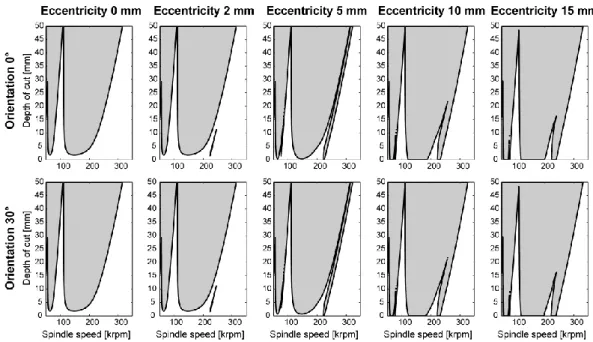
In this section, the effect of geometrical defects is investigated on the area of the first Hopf lobe, corresponding to High Speed Machining cutting conditions. In this case the separation of the dual mode of bending in two modes, by gyroscopic effect is negligible, less than +/- 0.36% at 300000 rpm. The stability lobes are plotted for various eccentricity and two defects orientation for extremely large spindle speeds Fig. 14.
Similarly to low spindle speed machining, the influence of the defect orientation on stability is negligible. As shown in Fig. 14, the stability lobes are the same for orientations of 0° and 30°. Complementary simulations have generalized this result for any orientation between 0° and 90°.
The important impact of the eccentricity is presented on Fig. 14, for 0, 2, 5, 10 and 15 mm values.
– First, the eccentricity reduces the lower limit of stability lobes. For example, for a speed of 150 krpm, with no eccentricity, the critical depth of cut is 2.5 mm, but with a defect of 5 mm, the critical depth of cut decreases practically to zero. Note that the tool is still cutting even if the nominal depth of cut is zero, since the actual depth of cut is not zero due to the relatively large eccentricity, which is commensurate to the depth of cut. Similarly to low speed machining, the defect of eccentricity has great impact on the process stability.
– Secondly, the eccentricity generates a special kind of instability next to the first Hopf lobe, similar to the well know flip lobe on interrupted milling [11]. This new instability is not generated by the interruption of the cutting, because without eccentricity the new unstable area is not show on the stability lobe (Fig. 14). It is rather related to the eccentricity of the workpiece. At small eccentricity values, an unstable island are born very similarly as it was shown in [34]. Then, for larger eccentricities, the island opens up and forms a stability lobe similarly to the period doubling stability lobes of low radial immersion milling or interrupted turning.
7
5. Concluding remarks
In this work, the stability of interrupted turning process with geometrical defects is investigated in a practical perspective of mass production.
A detailed analysis of the real cutting process is performed with special respect to the geometrical defects of the part in order to highlight the source of machine tool vibrations. Simplified models were developed for modelling the forced vibrations in interrupted turning, the gyroscopic effect and the mode coupling effect – primary chatter. These simplified formulations can be easily transposed in industrial applications because practically any of these vibration mechanisms may be the source of problems but complete investigations are usually out of reach in an industrial context.
A new stability modeling for interrupted turning is proposed. The model is based on the semi-discretization method, improved by the important aspect of interrupted cutting and geometrical inaccuracies (value and orientation of eccentricity). A sensitivity analysis of this model showed that the stability of the machining process is mainly sensitive to the value of the eccentricity, while the orientation of the defect from the interrupted cutting zones has no influence. The extrapolation in High Speed Machining, i.e. around the first stability lobe, show that a new zone of instability appears similarly to the flip lobes of low radial immersion milling or interrupted turning. This instability is only generated by the eccentricity and it’s not related to the interruption of the cutting process. These flip lobes have never been reported before in turning.
This global approach with improved models (forced vibrations, gyroscopic effect, and primary chatter) and a new regenerative interrupted model including geometrical defects can be used to build a systematic approach for analyzing
vibrations in other industrial contexts with geometrical defects. The authors emphasize the fact that in industrial contexts several vibration mechanisms are in competition and must be systematically compared, and that geometrical defects must be taken into consideration.
Acknowledgments
The authors acknowledge the French Ministry of Science and the Hungarian National Science Foundation under grant OTKA-K105433 for their financial support. Ford Aquitaine Industries provided the research opportunity.
References
[1] Taylor FW (1907) On the art of cutting metals. Trans ASME 28:31–350, §634A.
[2] Tobias SA, Fishwick W (1958) Theory of regenerative machine tool chatter, Engineer 205:199–203 238–239.
[3] Tlusty J, Polacek M (1963) The stability of the machine tool against self-exited vibration in machining, Proceedings of the International Research in Production Engineering Conference, ASME Press, Pittsburgh 465–474.
[4] Altintas Y, Budak E (1995) Analytical prediction of stability lobes in milling. CIRP Ann-Manuf Techn 44:357–362.
[5] Budak E (2006) Analytical models for high performance milling, Part I: cutting forces, structural deformations and tolerance integrity. Int J Mach Tools Manuf 46:1478–1488.
[6] Budak E (2006) Analytical models for high performance milling, Part II: process dynamics and stability. Int J Mach Tools Manuf 46:1489–1499.
[7] Gourc E, Seguy S, Arnaud L (2011) Chatter milling modeling of active magnetic bearing spindle in high-speed domain. Int J Mach Tools Manuf 51:928–936.
[8] Mousseigne M, Landon Y, Seguy S, Dessein G, Redonnet JM (2013) Predicting the dynamic behaviour of torus milling tools when climb milling using the stability lobes theory. Int J Mach Tools Manuf 65:47–57.
[9] Paris H, Peigné G, Mayer R (2004) Surface shape prediction in high speed milling. Int J Mach Tools Manuf 44:1567–1576.
[10] Lorong P, Coffignal G, Cohen-Assouline S (2008) Simulation du comportement dynamique d'un système usinant : modélisation de l'interaction outil/matière en présence d'une pièce flexible. Mec Ind 9:117–124.
[11] Insperger T, Mann BP, Stépán G, Bayly PV (2003) Stability of up-milling and down-milling, part 1: alternative analytical methods. Int J Mach Tools Manuf 43:25–34.
[12] Bayly PV, Halley JE, Mann BP, Davies MA (2003) Stability of interrupted cutting by temporal finite element analysis. J Manuf Sci Eng 125:220–225.
[13] Khasawneh FA, Bobrenkov OA, Mann BP, Butcher EA (2012) Investigation of period-doubling islands in milling with simultaneously engaged helical flutes. J Vib Acoust 134:021008.
[14] Insperger T, Stépán G (2004) Uptaded semi-discretization method for periodic delay-differential equations with discrete delay. Int J Numer Meth Eng 61:117–141
[15] Insperger T, Stépán G, Turi J (2008) On the higher-order semi-discretizations for periodic delayed systems. J Sound Vib 313:334–341.
[16] Insperger T, Stépán G (2011) Semi-discretization for time-delay systems – Stability and Engineering applications, Springer.
[17] Mann B.P, Insperger T, Stépán G, Bayly P.V (2003) Stability of up-milling and down-milling, part 2: experimental verification. Int J Mach Tools Manuf 43:35–40.
[18] Insperger T, Stépán G (2004) Stability analysis of turning with periodic spindle speed modulation via semidiscretization. J Vib Control 10:1835–1855.
[19] Zatarain M, Muñoa J, Peigné G, Insperger T (2006) Analysis of the influence of mill helix angle on chatter stability. CIRP Ann-Manuf Techn 55:365–368.
[20] Seguy S, Insperger T, Arnaud L, Dessein G, Peigné G (2011) Suppression of period doubling chatter in high-speed milling by spindle speed variation. Mach Sci Technol 15:153–171.
[21] Seguy S, Dessein G, Arnaud L, Insperger T (2010) Control of chatter by spindle speed variation in high-speed milling. Adv Mater Res 112:179–186.
[22] Altintas Y, Weck M (2004) Chatter Stability of Metal Cutting and Grinding. CIRP Ann-Manuf Techn 53:619–642.
[23] Olgac N, Sipahi R (2005) A Unique Methodology for Chatter Stability Mapping in Simultaneous Machining. J Manuf Sci Eng 127:791–800.
[24] Minis IE, Magrab EB, Pandelidis IO (1990) Improved Methods for the Prediction of Chatter in Turning Part 3: A Generalized Linear Theory. J Eng Ind 112:28–35.
[25] Chen CK, Tsao YM (2006) Stability analysis of regenerative chatter in turning process without using tailstock. Int J Adv Manuf Technol 29:648–654.
[26] Chandiramani NK, Pothala T (2006) Dynamics of 2-dof regenerative chatter during turning. J Sound Vib 290:448–464.
[27] Lehotzky D, Insperger T (2012) Stability of turning processes subjected to digital PD control. Period Polytech-Mech Eng 56:33–42.
[28] Gourc E, Seguy S, Michon G, Berlioz A (2013) Chatter control in turning process with a nonlinear energy sink. Adv Mater Res 698:89–98.
[29] Insperger T, Barton DAW, Stépán G (2008) Criticality of Hopf bifurcation in state-dependent delay model of turning processes. Int J Nonlin Mech 43:140–149.
[30] Dombovari Z, Barton DAW, Wilson RE, Stepan G (2011) On the global dynamics of chatter in the orthogonal cutting model. Int J Nonlin Mech 46:330–338.
[31] Rigal J, Pupaza C, Bedrin C (1998) A model for simulation of Vibrations During Boring Operations of Complex Surfaces. CIRP Ann-Manuf Techn 47:51–54.
[32] Lazoglu I, Atabey F, Altintas Y (2002) Dynamic of Boring Processes: Part III - Time Domain. Int J Mach Tools Manuf 42:1567–1576.
[33] Budak E, Ozlu E (2007) Analytical Modeling of Chatter Stability in Turning and Boring Operations: A Multi-Dimensional Approach. CIRP Ann-Manuf Techn 56:401–404.
[34] Szalai R, Stépán G (2006) Lobes and Lenses in the Stability Chart of Interrupted Turning, J Comput Nonlinear Dynam 1:205–211.
[35] Schmitz TL, Couey J, Marsh E, Mauntler N, Hughes D (2007) Runout effect in milling: Surface finish, surface location error, and stability. Int J Mach Tools Manuf 47:841–851.
[36] Insperger T, Mann BP, Surmann T, Stépán G (2008) On the chatter frequencies of milling processes with runout. Int J Mach Tools Manuf 48:1081–1089.
[37] Siddhpura M, Paurobally R (2012) A review of chatter vibration research in turning. Int J Mach Tools Manuf 61:27–47.
[38] Arnaud L, Dutilh V, Dessein G, Saussol A (2008) Arnaud M Analyse et réduction des vibrations d’usinage d’une pièce automobile produite en grande série. XVI Symposium VIbrations, SHocks & NOise VISHNO, Paris.
List of Figures Captions
Fig. 1. Sectional view of the transmission (a), support of the pump (b), ring workpiece (c) and detail about machined surface (d)
Fig. 3. Geometrical defects of the workpiece
Fig. 4. Visual analysis of the part by micrography
Fig. 5. Audio spectral
Fig. 7. Simplified gyroscopic model
Fig. 9. Movement during mode coupling
Fig. 11. Classical stability lobes for the industrial context, without geometrical defect
Fig. 12. Map of stability, influence of the geometrical defects (eccentricity and orientation) on the maximal chatter free depth of cut. Left: 2230 rpm (Pt. A). Right: 2250 rpm (Pt. B)
Fig. 14. Stability lobes with geometrical defects (eccentricity and orientation) at High Speed Machining, around the first lobe
List of Tables
Table 1 Modal parameters identified
m k 0
0.1135 kg 0.7 % 15×106 N/m 11498.4 rad/s
Table 2 Cutting parameters
tci tfi Kt