Science Arts & Métiers (SAM)
is an open access repository that collects the work of Arts et Métiers Institute of
Technology researchers and makes it freely available over the web where possible.
This is an author-deposited version published in: https://sam.ensam.eu Handle ID: .http://hdl.handle.net/10985/11241
To cite this version :
Wael YOUNES, Eliane GIRAUD, Fredj MONTASSAR, Philippe DAL SANTO, Sjoerd VAN DER VEEN - Creep Forming of an Al-Mg-Li Alloy for Aeronautic Application - 2016
Any correspondence concerning this service should be sent to the repository Administrator : archiveouverte@ensam.eu
Creep Forming of an Al-Mg-Li Alloy for Aeronautic
Application
Wael Younes
1,2, a), Eliane Giraud
2, b),
Montassar Fredj
2, Philippe Dal Santo
2and
Sjoerd van der Veen
3,c)1
IRT Jules Verne, Chemin du Chaffault, 44340 Bouguenais – France
2 LAMPA, ENSAM, 2 boulevard du Ronceray, 49035 Angers, Cedex 01 – France
3Airbus Structures Research, Materials & Processes, ESCRNM, 18 rue Marius Terce, 31300 Toulouse - France
a)
wael.younes@irt-jules-verne.fr
b) eliane.giraud@ensam.eu c) sjoerd.van-der-veen@airbus.com
Abstract. Creep forming of Al-Mg-Li alloy sheets is studied. An instrumented bulging machine is used to form a double
curvature panel at a reduced scale. The deformation of the work-sheet is ensured by a 7475 aluminum alloy lost sheet deformed by a gas pressure applied on its upper surface. A numerical model using the ABAQUS software is developed in order to obtain the pressure law and to ensure the forming conditions during the cycle. This model is validated by comparing experiments and numerical results in terms of deformed shape and thickness evolution.
INTRODUCTION
Creep forming process is more and more used in aircraft industries to elaborate large double curvature panels in aluminum alloys essentially [1]. This process includes generally three main stages. In the first stage, the sheet is placed on a die and is heated until a specific temperature. This temperature can correspond to a solution temperature (solution forming process) or an ageing temperature (creep age forming process) of the alloy. During the second stage, the sheet is deformed to conform to the shape of the die. Vacuum between the sheet and the die is generally used to perform the deformation. Supplement pressure, by using a gas pressure or a punch, can also be applied on the upper surface of the sheet to force close contact with the die surface. Strains introduced in the sheet remain generally elastic due to the use of not severe curvature for the part. In the third stage, after a given holding time at the temperature, the part is cooled and some springback occurs leading to a final shape between the undeformed shape and the die shape. The holding time at high temperature allows stress relaxation as well as microstructural changes such as precipitation at ageing temperature. Creep forming process has numerous advantages such as low residual stresses (due to stress relaxation) or low forming stresses (which are inferior to the yield point of the alloy).
In this paper, the elaboration, by creep forming, of a double curvature panel from the nose of an aircraft is studied. The considered part is a smaller version of the real one (i.e. 10% of the initial part) and is made of aluminum-magnesium-lithium alloy. This type of alloy is quite interesting for aeronautic applications due to the enhancement of the structure lightening as well as the strengthening of the alloy compared to classical aluminum alloys [2]. The forming of the part is performed at high temperature (350°C), which corresponds to the solution treatment temperature of the alloy. An instrumented bulging demonstrator developed by the LAMPA is used [3]. As shown in Fig. 1, a double curvature die is fixed on a support tool, placed inside the furnace. The work-sheet is put
freely on the die. The lost sheet is placed on the top surface of the support tool, at few millimeters above the work-sheet. The system is clamped by the furnace closure. Thus, during the forming process, a gas (i.e. argon) pressure is applied on the upper side of the lost sheet. During the cycle, the deformation of the lost sheet induces the conforming of the work sheet to the die shape. In this study, a 7475 aluminum sheet of 2mm in thickness is chosen as lost sheet, due to its performances in superplastic forming.
(b) Lower part of the furnace
(a) General sketch of the bulging machine (b) Elements present in the forming zone
FIGURE 1. Sketch of the creep forming process used in this study
MATERIALS CHARACTERIZATION AND MODELING
Mechanical Behavior of the Lost Sheet
The superplastic behavior of 7475 aluminum alloy has already been studied by Yang et al. [4] but at temperatures higher than 450°C. It exhibits a great superplastic behavior at a temperature of 517°C and for strain rates lower than 1.10-4/s. For temperatures lower than 517°C, the alloy losses its superplastic characteristic but the strain at failure remains sufficiently high to allow its use as lost sheet for the studied application. Data obtained by Srivastava et al. [5] after experimental campaigns performed at 350°C on a 7xxx aluminum alloy are used in this study to predict the flow stress of the lost alloy.
A classical material law (equation 1) is used to predict the behavior of the lost sheet. K is a constant of the material, m and n corresponds to the strain rate sensitivity of the alloy and the strain hardening, respectively. It is assumed that the alloy exhibits no strain hardening during its plastic deformation (i.e. n=0). By using the experimental data of [5], K and m can be identified.
Creep Behavior of the Al-Mg-Li Alloy
Experimental Procedure
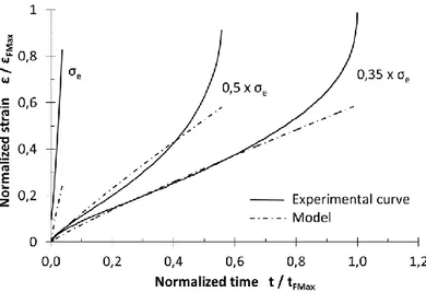
A Gleeble 3500 machine is used to perform creep experiments at a temperature of 350°C. Specimens are taken in a rolled plate, 2mm in thickness, supplied by Constellium. They are sustained to a constant stress until their failure by monitoring in real time the tensile strength applied on them. An extensometer is used to measure the deformation. Specimens are heated by Joule effect with a heating rate of 10K/s until the test temperature. The temperature is measured by a K-type thermocouple welded in the central part. Experiments are started after a holding time of 20s to ensure a homogeneous temperature within the gauge length of the sample (±5°C around the test temperature). This holding time is also sufficient to allow the solution treatment of the alloy. The charge is applied with a rate about 5MPa/s and until values which remain inferior to the yield stress σe of the alloy i.e.: 𝜎𝑒, 0,5 × 𝜎𝑒and0,35 × 𝜎𝑒.
Experimental Results
Time-strain curves obtained for each experimental configuration are shown in Fig. 2. The results are normalized by the time at failure tFMax and strain at failure εFMax obtained for the lowest applied stress (i.e. 0,35 × 𝜎𝑒). It can be
noticed that: (i) primary creep is negligible, (ii) strain at failure and time at failure decrease when increasing the stress level and (iii) tertiary creep is reached quite rapidly whatever the configuration i.e. for time inferior to 1h. Fracture surface shows dimples and underlines the formation of cavities during creep deformation.
FIGURE 2. Time-strain normalized curves obtained by performing creep experiments at high temperature on an Al-Mg-Li alloy
(solid lines) and by applying the Bailey-Norton law (dotted lines)
Modeling of the Creep Behavior of the Al-Mg-Li Sheet
The law of Bailey-Norton (equation 2) is employed to describe the creep behavior of the alloy. A, n and m are material parameters (with: A > 0, n > 0 and -1 < m ≤ 0) which are identified following the procedure given by Maximov el al. [6]. This model allows predicting the secondary creep so that the creep damage (or tertiary creep) is neglected. A comparison between experimental curves and modeled curves are given in Fig. 2. It can be noted that the secondary creep is well predicted by the law for the lowest applied stresses. When the applied stress during creep deformation is equal to the yield stress, creep damage occurs at an early stage leading to some errors in the prediction.
NUMERICAL SIMULATION OF THE FORMING PROCESS
Numerical Model
The numerical model used to simulate the forming process is shown in Fig. 3a. The die is modeled by a discrete rigid surface. The Al-Mg-Li flange and the 7475 lost sheet are meshed using linear shell elements with reduced integration (S4R element in ABAQUS). The average dimension of the elements is about 8, 10 and 12mm for the work sheet, the die and the lost sheet, respectively. Surface to surface contacts with hard contact and coulomb friction are used for the flange to die, the flange to lost sheet and the lost sheet to die interfaces. In a first approach, a global friction coefficient of 0.1 is chosen for all contacts. The exterior edges of the lost sheet and the reference point of the die are fixed (Fig. 3b). The deformed flange is stabilized by the initial contact condition with the die. A pressure condition is applied on the top face of the lost sheet. The pressure amplitude is controlled by a Fortran subroutine to ensure a strain rate of about 5.10-5 s-1. The material behaviors are modelled by creep laws implemented in user subroutines. The lost sheet material law is coupled to the pressure control algorithm. The solving process uses the implicit time integration scheme of ABAQUS Standard with creep analysis steps (*visco).
(a) (b)
FIGURE 3. Numerical model of the forming process
Numerical Results
(a) Strain developed in the lost sheet (7475 alloy) (c) Contact play between the Al-Mg-Li sheet and the die
(b) Stress developed in the work sheet (Al-Mg-Li alloy) (d) Pressure law applied on the lost sheet
Figure 4 shows the main numerical results obtained by applying the model described above. The maximal strain developed in the lost sheet (Fig. 4a) is about 21%. This strain remains inferior to the strain at failure of this alloy under the considered thermomechanical conditions, which should allow forming without fracture of the sheet. The Al-Mg-Li sheet shows maximal stress level inferior to its yield stress (Fig. 4b). Contact between the work-sheet and the die is relatively good (Fig. 4c): the gap between these two elements is inferior to 0,3mm, which underlines the good forming of the part. The pressure law which controls the deformation of the lost sheet is given in Fig. 4d. The pressure increases continuously until a maximal value of 18 bar. The first contact between the lost sheet and the work sheet occurs after 650s. The work sheet matches the die after 8500s. The pressure is maintained until a forming time of 10800s to allow the relaxation of the work sheet: stress relaxation is thus about 20%.
VALIDATION OF THE NUMERICAL SIMULATION
Experimental forming of a double curvature part using the machine described in Fig. 1 as well as the pressure law given in Fig. 4d is realized. The lost sheet has a diameter of 290mm whereas the work sheet has a diameter of 178mm. The deformed sheets obtained after the forming are shown in Fig. 5a: the central zone of the lost sheet has been deformed by the gas pressure and the Al-Mg-Li has been integrally deformed and shows the double curvature. The springback of the work sheet is not important: as shown in Fig. 5b, the work sheet matches the die shape.
(a) (b)
FIGURE 5. Parts obtained after the creep forming with a free bulging machine
Good agreement is found between experimental and numerical results in terms of displacement at the dome apex of the lost sheet, thickness evolution in the work sheet and deformed shapes.
The measured displacement at the dome apex of the lost sheet (Fig. 6a) increases then keeps a constant value, which underlines the fact that the sheets have reached the die. Some errors are present compared to the numerical displacement: the increase in pole displacement is more important for the numerical simulation. This can be due to the material parameters used for the lost sheet taken from literature data.
The thickness evolution range, in the numerical part as well as in the experimental part, is about 0,01mm from the center to the edge of the part. The measured gap at the central point between the work sheet and the die is in the same range that the numerical one (i.e. 0,15mm).
A comparison between the numerical and experimental deformed shape is shown in Fig. 6b. The deformed shell mesh has been exported like a points cloud from ABAQUS to the CAD software CATIA V5. The experimental shape has been designed from points measured with a tridimensional machine. A good agreement between the obtained shapes is found with an average error of curvature radii of 2% in their central zones. The maximum errors between the mid-surface of the measured shape and the deformed shell mesh are localized on their edges. These errors can be due to the modelling of the final step of the process (cut of pressure, cooling, …) which will be improved in future works.
(a) Displacement at the dome apex of the lost sheet (b) Deformed shapes comparison
FIGURE 6. Comparison between experimental and numerical results
CONCLUSION AND PERSPECTIVES
Creep forming, using a lost sheet, of a double curvature panel in Al-Mg-Li alloy has been investigated. The creep behavior of the Al-Mg-Li alloy at high temperature has been studied and modeled using the Bailey-Norton law. The mechanical behavior of the lost sheet has also been modeled with a classical law using literature data. A numerical model has then been developed to predict the forming of the work-sheet a well as the pressure law to apply on the lost sheet during the process. The forming of a double curvature part has finally been performed by using a bulging machine and comparison between experiments and numerical results shows a good agreement. Future works will consist in: (i) modifying the numerical model to take a more complex creep model into account in order to predict creep damage, (ii) using the numerical model to predict the creep forming of a part at an industrial scale.
ACKNOWLEDGMENTS
This paper is part of the METAFOR project managed by IRT Jules Verne (French Institute in Research and Technology in Advanced Manufacturing Technologies for Composite, Metallic and Hybrid Structures). The authors wish to associate the industrial and academic partners of this project; respectively ACB, STELIA, AIRBUS, CONSTELLIUM, ENSAM.
REFERENCES
1. L. Zhan, J. Lin and T.A. Dean, Int. J. Machine Tools & Manufacture 51, 1-17 (2011) 2. R.J.H. Wanhill, Int. J. Fatigue 16, 3-20 (1994).
3. Y. Aoura, D. Ollivier, A. Ambari, P. Dal Santo, J. Mater. Proces. Tech. 145, 352-359 (2003)
4. J. Yang, S. Boude, E. Giraud and P. Dal Santo, “The strain rate sensitivity and constitutive equations including damage for the superplastic behavior of 7xxx aluminum alloys”, in 11th International Conference on Numerical Methods in Industrial Forming Processes-2013, AIP Conference Proceedings 1532, pp. 623-629
5. V. Srivastava, J.P. Williams, K.R. McNee, G.W. Greenwood, H. Jones, Mater. Sci. Eng. A382, 50-56 (2004) 6. J.T. Maximov, G.V. Duncheva, A.P. Anchev and M.D. Ichkova, Comp. Mater. Sci. 83, 381-393 (2014)