Science Arts & Métiers (SAM)
is an open access repository that collects the work of Arts et Métiers Institute of
Technology researchers and makes it freely available over the web where possible.
This is an author-deposited version published in: https://sam.ensam.eu
Handle ID: .http://hdl.handle.net/10985/10305
To cite this version :
Franck SCUILLER - Study of a supercapacitor Energy Storage System designed to reduce frequency modulation on shipboard electric power system - In: 38th Annual Conference on IEEE Industrial Electronics Society, Canada, 2012-10 - IECON 2012 - 2012
Any correspondence concerning this service should be sent to the repository Administrator : archiveouverte@ensam.eu
Study of a Supercapacitor Energy Storage System
designed to reduce frequency modulation on
shipboard electric power system
Franck Scuiller
Institut de Recherche de l’Ecole Navale, French Naval Academy BCRM BREST - EN / GEP
CC 600 - 29240 BREST Cedex 9 - FRANCE franck.scuiller@ieee.org
Abstract—On a shipboard electric power system, in steady-state operations, the electric grid disturbances due to powerfull periodic pulsed loads are estimated by the voltage and frequency modulations. Energy Storage System (ESS) with fast discharge ability allows to reduce the stress on the grid components and to meet the design standard requirements. This paper focuses on the sizing and simulation of a supercapacitor ESS (SC ESS). Regarding the chosen topology, the SC bank is directly connected to the grid converter (without DC bus stage) because reliability, efficiency and ability to ensure other functions (as voltage sag mitigations) are expected. Regarding the SC ESS management, the DC voltage is controlled at any time and SC ESS charge and discharge are ordered by stepping the reference DC voltage to minimal value or maximal value. Furthermore SC ESS charge/discharge cycle is synchronized with the pulsed load with a smooth time advance in order to compensate the lower power rise of the ESS in comparison with the one of the pulsed load. The results obtained with the shipgrid simulator are convincing: the frequency modulation is significantly reduced (by more three times) and becomes compliant with the standard requirement. Regarding the generator side, the governor torque variations are strongly mitigated.
I. INTRODUCTION
Every electric power systems are subject to voltage fluc-tuations due to load or generation configuration changes. In particular, marine electric power system usually integrate load whose power level is significant relative to the generator power (particularly in case of electric propulsion). Consequently marine electric power systems are also subject to frequency change. To ensure safe operations, standards impose to limit the voltage and frequency excursion in transient and steady-state operations. For electric power system of NATO warship, the STANAG-1008 standard is usually applied [1]. For ship-grid, the pulsed loads (as radar or sonar) can be particularly embarrassing [2]: for conventional governors (as diesel for ex-ample), the pulsed loads appear as periodic fast varying power demands that can not be balanced without speed fluctuations. Consequently, when the pulsed load is running, the generators can be always in transients which can stress prime-mover and exciter actuators. Regarding the power quality, frequency and voltage modulation troubles can occur which can lead to sensitive load mis-operations and grid instability. For the
generator side, it can be shown that mechanical inertia or nominal power increase does not allow efficiently reducing the frequency variations and voltage dip due to the pulsed loads: genset oversizing is useless [3]. Consequently, energy storage systems (ESS) with fast discharge ability are often the only solution to efficiently compensate the pulsed loads and then to significantly alleviate the frequency and voltage disturbances. In [3], the ability of a pulsed power compensator to make a shipgrid compliant with the STANAG standard is demon-strated. However the simulations reported in this study are based on a perfect energy storage: storage type, charge and discharge dynamic and storage level control are not taken into account. In this paper, a supercapacitor ESS is sized and simulated in order to better estimate the effective dynamic performances of such a pulsed power compensator. The paper is divided into three parts. By introducing a simple shipgrid case study, the first part aims to clearly illustrate the difficulty for the designer to correctly predict the compliance of the grid with STANAG standard when pulsed loads are integrated. The choice of a particular supercapacitor ESS is justified. In the second part, the supercapacitor bank is sized by considering the pulsed load characteristics. In the last part, the control strategy of the SC ESS is analysed and tested with a dedicated ESS simulator. Finally the SC ESS model is integrated into a complete shipgrid simulator (where the generator is voltage and speed regulated) and the SC ESS performances are more accurately estimated.
II. PROBLEM ANALYSIS
A. Frequency and voltage disturbances due to pulsed load
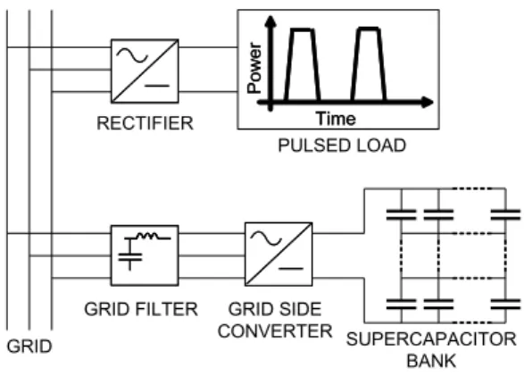
In order to clearly illustrate the problematic of this paper, a simplified shipboard system is defined and simulated by using Matlab/Simulink with the SimPowerSystem Toolbox [4]. Depicted by figure 1, the ship grid integrates:
∙ a 1250kVA diesel-alternator that is speed and voltage regulated to maintain the grid frequency at 60Hz and the grid phase-to-phase voltage at 440V (RMS)
∙ a linear load of 600kW with a power factor of 0.8 (inductive load)
∙ a 200kW pulsed load
The pulsed load is supposed to have the following character-istics:
∙ peak power of 200kW
∙ pulse length of 0.5s
∙ duty cycle of 10% (the pulsed load periodicity is then 5s)
∙ maximum power slope lower than 20MVA/s
The model consists in a diode rectifier that supplies a perfect current source ordered to simulate the pulsed power. The step current order is first-order filtered to make the pulsed power slope lower than 20MVA/s.
Fig. 1. Simplified shipgrid simulated with Matlab/Simulink SPS
This simple shipgrid must comply with military standard STANAG 1008 [1]. According to this standard, the regular repeated power demanded by the pulsed loads can lead to excessive voltage and frequency modulations. Voltage and frequency modulations measure the time periodic variations that are longer than one-cycle time of the AC grid. The modulation of signal𝑥 can be mathematically defined by the following expression:
𝑚𝑥= 𝑥𝑚𝑎𝑥2𝑥− 𝑥𝑚𝑖𝑛
𝑛𝑜𝑚 (1)
In relation (1),𝑥 denotes:
∙ the frequency for the calculation of the frequency mod-ulation
∙ the rms or peak line-to-line voltages for the calculation of the voltage modulations
To meet STANAG 1008 requirements, the frequency and voltage modulations must be lower than 0.5% and 2% respec-tively. Regarding the ship grid design, STANAG 1008 advises limiting the pulsed loads reactive power 𝑄𝑝𝑢𝑙𝑠𝑒 and active power 𝑃𝑝𝑢𝑙𝑠𝑒 regarding the total generators power supply
𝑆𝑠𝑢𝑝𝑝𝑙𝑦 at the occurrence of the pulse:
{
𝑄𝑝𝑢𝑙𝑠𝑒< 0.065𝑆𝑠𝑢𝑝𝑝𝑙𝑦
𝑃𝑝𝑢𝑙𝑠𝑒 < 0.25𝑆𝑠𝑢𝑝𝑝𝑙𝑦 (2)
The recommendations can be unsufficient as for the case studied in this paper. This statement is illustrated by figure 2-a that locates the pulsed power point in (apparent power, power factor) plan. Whereas the pulse power point belongs to the allowed aera (that is drawn according to relation (2)), figure 2-b shows that the pulsed load leads to an excessive modulation of about0.7% (according to the simulation).
0 0.05 0.1 0.15 0.2 0.25 0.3 0 0.1 0.2 0.3 0.4 0.5 0.6 0.7 0.8 0.9 1
Pulse Load Apparent Power (pu, relative to Supply Power)
Pulse Load Power Factor
Allowed Aera
Forbidden Aera
(a) Case study pulsed load in STANAG 0 1 2 3 4 5 6 7 8 910 11 12 13 14 15 16 0.99 0.992 0.994 0.996 0.998 1 1.002 1.004 1.006 1.008 1.01 Time (s) Frequency (pu, 60Hz)
(b) Overmodulation example due to pulsed load
Fig. 2. Case study pulsed load rating power agreement with STANAG limitations despite grid frequency overmodulation (0.7% versus 0.5% allowed)
B. Common pulsed power compensator systems
In order to alleviate the disturbances, the standard also suggests to store kinetic or electrical energy to supply the pulsed loads. The common device is sketched out in figure 3. This kinetic energy storing system is based on a flywhell that mechanically separates the grid from the pulsed load. In charging mode, the flywhell is driven by an induction machine connected to the grid with charging switches. On discharging mode, the flywhell supplies a dedicated synchronous machine that supplies the pulsed load through a rectifier. Clearly studied and simulated in [5], this kind of system is quite efficient to reject voltage and frequency disturbances due to pulsed load operations. The flywhell system is generally sized to compensate several consecutive pulses without being restored between two pulses. This design choice improves the overall performances of the system because the stored energy is high. Unfortunately this design choice also increases the volume and the weight of the system. Hence the common system is heavy and requires maintenance. It can be useful to look for more performant solutions that take advantage on power electronic improvements. That is why an original ESS is looking for in this paper.
Fig. 3. Common pulsed load system layout integrating a dedicated flywhell compensator
C. Choice of a parallel supercapacitor compensator
An ESS compensator can be connected in series with the pulsed load or in parallel. In this paper, the ESS is wanted to be electrically separated from the pulsed load: this requirement means that the pulsed load and the compensator are not supplied from the same breaker. The choice of a parallel compensator beside a series compensator is then natural (whereas for dedicated pulsed load compensators, series topology seems better than parallel topology as stated
in [6]). Parallel compensation makes easier to design the ESS to ensure other functions as reactive power compensation and harmonic filtering.
Flywhell and supercapacitor ESS are competitive for the case study in terms of power range and cycling ability. Regarding charge and discharge dynamic, flywheel systems have a time response shorter than supercapacitor, which is particularly advantageous to compensate short duration pulsed loads: in [6], it is claimed that time response of flywhell energy storage systems are only limited by the power electronics. However, the minimal time response of supercapacitors is about 0.5s, which can be sufficient for the present application. For flywheel or supercapacitor storage, the connection to the grid is similar: it consists of a grid filter and a bi-directional power rectifier that generate a DC bus.
Differences concern the way to connect and then to control the ESS. As the flywheel system is necessarily associated with a rotating machine, an inverter is added for drive purpose: a back-to-back topology is then obtained. Such a device is anal-ysed and simulated in [7]. This kinetic energy storage system is electrically independant from the pulsed load in opposition to the common device described in figure 3 (that is also based on a flywheel storage). For this study, supercapacitor storage is prefered to flywhell storage: a simplified maintenance and a better reliability are expected because there is no mechanical part.
In this study, the topology sketched out by figure 4 is foreseen. The supercapacitor storage directly constitutes the DC bus as in some Uninterruptable Power Supplies [8]. In comparison with the common solution where a chopper is inserted between the DC bus and the SC storage, the removing of the chopper stage favours the efficiency. However, with this topology, the full discharge of the ESS is not possible because the DC voltage must always remain sufficiently high to control the power transfer between the grid side and the DC side. For the case study, this drawback can actually be considered as an advantage: taking into account the minimal time response of supercapacitor (about 0.5s) and the high power rise of the pulsed load, to rate the system for partial discharge can mitigate the slight too low dynamic of the supercondensator. On a pratical point of view (and as it can be seen in figure 4), a supercapacitor storage is usually made with several elementary supercapacitors (so-called cells) connected in series and parallel to form a bank. To make possible the SC direct connected topology, the SC bank must behave as a module. A supercapacitor module is a device that integrates several cells with a balancing system [9].
III. SUPERCAPACITOR BANK SIZING
A. ESS design specifications from pulsed load characteristics
The supercapacitor Energy Storage System (SC ESS) is designed to compensate the pulsed load described in subsec-tion II-A. The main useful parameters of the pulsed load are summarized by the following relationship:
𝑃𝑝𝑢𝑙𝑠𝑒 = 200𝑘𝑊 𝑡𝑑= 0.5𝑠 𝑇 = 5𝑠 (3)
Fig. 4. Parallel direct supercapacitor based compensator layout with storage system directly connected on the DC bus
Consequently, the SC ESS must be sized in order:
∙ to provide to the grid the needed compensation power𝑃𝑑 during 𝑡𝑑= 0.5𝑠 when the pulsed load is running
∙ to take from the grid its required restoring power𝑃𝑐when the pulsed load is in pause (between two pulses) By introducing a supposed average efficiency for the ESS denoted𝜂𝐸𝑆𝑆, if the ESS is described in receptor convention, the discharge power 𝑃𝑑 and the charge power 𝑃𝑐 can be expressed by considering the main pulsed load parameters listed in (3): ⎧ ⎨ ⎩ 𝑃𝑑= −𝑃𝜂𝑝𝑢𝑙𝑠𝑒 𝐸𝑆𝑆 𝑃𝑐=𝑃𝜂𝑝𝑢𝑙𝑠𝑒 𝐸𝑆𝑆 𝑡𝑑 𝑇 − 𝑡𝑑 (4) B. Supercapacitor model
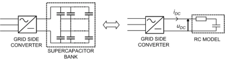
The voltage across the supercapacitor storage system is quite high: the phase-to-phase grid voltage is 440V which leads to a minimal DC voltage bus equal to 750V. In this paper, the SC bank forms a module. Hence the load between the different supercapacitors is supposed perfectly balanced. Consequently the series and parallel connections of the whole supercapacitors are modelized with a single supercapacitor.
First-order RC model is the more simple way to simulate a supercapacitor bank. For the present study, the main drawback of such a model is its inability to capture the nonlinear rise and fall of supercapacitor voltage after the charging and discharging modes [10]. However the simplicity of this model is particularly attractive in a global simulation that aims to estimate frequency and voltage transients in a shipgrid. Besides, according to [11], although RC model can not reflect the long-term behavior of the supercapacitor, it can be used to simulate fast varying power operations. Finally, for sizing and simulation purposes, the supercapacitor bank is modelized by a capacitor in series with a resistor as shown by figure 5: the resistor (usually called equivalent series resistor) models the supercapacitor ohmic losses and the capacitor models the storage.
Fig. 5. RC model for the supercapacitor bank
C. Supercapacitor sizing
The required supercapacitor value is calculated by con-sidering the simple RC model. The supercapacitor voltage corresponds to the DC bus voltage𝑢𝐷𝐶. If𝐶𝑆𝐶 is the super-capacitor value,𝑅𝑆𝐶 the associated resistor, 𝑖𝐷𝐶 the current through the supercapacitor and 𝑞 the supercapacitor charge, the voltage equation that describes the DC bus behaviours is:
𝑢𝐷𝐶= 𝑅𝑆𝐶𝑖𝐷𝐶+𝐶𝑞
𝑆𝐶 (5)
The capacitor is assumed to be discharged with constant current 𝐼𝑆𝐶,𝑑 during time 𝑡𝑑 from maximum DC voltage
𝑈𝐷𝐶,𝑚𝑎𝑥 to minimun DC voltage 𝑈𝐷𝐶,𝑚𝑖𝑛. By expressing
capacitor charge change with current current discharge, equa-tion (5) becomes:
𝑈𝐷𝐶,𝑚𝑖𝑛− 𝑈𝐷𝐶,𝑚𝑎𝑥= 𝑅𝑆𝐶𝐼𝑆𝐶,𝑑+𝐼𝑆𝐶,𝑑𝐶 𝑡𝑑
𝑆𝐶 (6)
By introducing the time constant 𝜏𝑆𝐶 = 𝑅𝑆𝐶𝐶𝑆𝐶, the required supercapacitor is:
𝐶𝑆𝐶 = 𝑈𝐼𝑆𝐶,𝑑(𝜏𝑆𝐶 + 𝑡𝑑)
𝐷𝐶,𝑚𝑎𝑥− 𝑈𝐷𝐶,𝑚𝑖𝑛 (7)
Discharge current 𝐼𝑆𝐶,𝑑 can be estimated from the required ESS discharge power𝑃𝑑 (see equation (4)) and grid phase to phase RMS voltage𝑈: 𝐼𝑆𝐶,𝑑= √ 2 3 𝑃𝑑 𝑈 (8)
The final relationship to estimate the required supercapacitor value is then: 𝐶𝑆𝐶 = √ 2 3 ∣𝑃𝑑∣ 𝑈 𝜏𝑆𝐶+ 𝑡𝑑 𝑈𝐷𝐶,𝑚𝑎𝑥− 𝑈𝐷𝐶,𝑚𝑖𝑛 (9)
Time constant𝜏𝑆𝐶 must be lower as possible. For supercapac-itor technology,0.5𝑠 seems to be the minimum time response. The analysis of some supercapacitor datasheet (as [12]) shows that it seems possible to design a module for the pulsed power compensation studied in this paper. Concerning the voltages, to chose𝑈𝐷𝐶,𝑚𝑖𝑛= 750𝑉 and 𝑈𝐷𝐶,𝑚𝑎𝑥= 1500𝑉 allows to obtain a maximal theoretical state of discharge of 75%, which is acceptable. With the assumption of a time constant𝜏𝑆𝐶 of about0.5𝑠, the required supercapacitor is about 0.61𝐹 .
IV. ESSMODELING AND SIMULATION
A. Control strategy analysis
The ESS must behave as a fast varying power generator. Hence it is interesting to control the ESS actuator (the AC/DC converter) with active and reactive power reference (as it was done in the preliminary study done in [3]). Active and reactive power references are direcly converted into grid filter current references. In the grid voltage dq frame, the dq reference current are given by the following relationship:
⎧ ⎨ ⎩ 𝑖𝑞= √ 2 3 𝑃 𝑈 𝑖𝑑= √ 2 3 𝑄 𝑈 if 𝑣𝑑𝑞= 𝑈 √ 2 3𝑞 (10)
According to (10), 𝑖𝑞 current clearly determines the active power exchange between the AC side (grid side) and the DC side (energy storage side). If the converter is perfect, the DC curent directly relates to𝑖𝑞 current and𝑞 modulation function
𝑚𝑞:
𝑖𝐷𝐶= 32𝑚𝑞𝑖𝑞 (11) When the ESS is discharging, DC current is negative and the supercapacitor voltages decreases whereas, in charging mode, DC curent is positive and the supercapacitor voltage increases. To perfectly control the active power exchange and to ensure safe charge and discharge operations, it is necessary to control the energy storage level of the supercapacitor banks at any time. Consequently, a DC voltage controller is integrated. The ESS active power is thus delivered by changing the DC voltage bus reference.
The supercapacitor bank is sized with the assumption of a discharge at constant DC current between the maximum DC voltage (1500V) and the minimum DC voltage (750V). To achieve the supercapacitor discharge at the rated power
𝑃𝑑 = −200𝑘𝑊 during 𝑡𝑑 = 0.5𝑠, the reference DC voltage
must be stepped from 𝑈𝐷𝐶,𝑚𝑎𝑥 to𝑈𝐷𝐶,𝑚𝑖𝑛 during𝑡𝑑. After discharging, the reference DC voltage must be stepped from
𝑈𝐷𝐶,𝑚𝑖𝑛to𝑈𝐷𝐶,𝑚𝑎𝑥. With such a strategy, it is necessary to
secure the supercapacitor bank and to avoid too fast restoring operation. Consequently the DC current discharge ordered by the DC voltage controller must be limited. According to relation (11), this limitation can be achieved by limiting the reference current 𝑖𝑞,𝑟𝑒𝑓. The mininal current (low saturation) is calculated by considering the rating discharge power of the compensator whereas the maximal current (high saturation) is calculated by considering the rating charge power of the compensator.
B. Energy Storage System simulation
In a first step, a dedicated ESS simulator is performed for three goals:
∙ to define and tune the voltage and current controllers
∙ to test the ESS storage system charge and discharge strategy
Developped with Matlab/Simulink, this dedicated simulator is depicted in figure 6. The quantities are expressed in the grid dq frame and the converter is assumed to be perfect (perfect switch, no losses, sinusoidal modulation). The grid filter block and the supercapacitor block constitute the physical part of the system: they introduce the state variables to be controlled that are the grid current and the DC voltage. The current controller drives the AC/DC converter in order to follow the current references:
∙ 𝑖𝑑 reference is directly calculated from relation (10) considering the requiring reactive power defined in the strategy block
∙ 𝑖𝑞 reference is calculated by the DC voltage controller in
order to follow the DC voltage reference that defines the wanted power exchange defined in the strategy block. Both voltage and current controllers are PI type with anti-windup saturations. For the voltage controller, the saturation current are calculated by considering the rating charge and discharge powers (as explained at the end of subsection IV-A).
SUPERCAPACITOR BANK i DCV_DC STRATEGY Q_ref V_DC_ref GRID VOLTAGE vd grid vq grid GRID FILTER vd grid vq grid vd sct vq sct id iq DIRECT CURRENT REFERENCE vq grid Q_ref id_ref DC VOLTAGE SENSOR V_DC V_DC_mes DC VOLTAGE CONTROLLER V_DC_ref V_DC_mesiq_ref DC CURRENT CALCULATION m_q iq i_DC CONVERTER m_d m_q V_DC vd SCT vq SCT AC CURRENT CONTROLLER id_ref iq_ref id_mes iq_mes V_DC_mes m_d_ESS m_q_ESS
Fig. 6. ESS simulator with DC voltage and grid current controllers The dedicated ESS simulator is used to check if the required discharge (−200𝑘𝑊 for 0.5𝑠) and charge power (to restore during 4.5𝑠) from the compensator can be realized with the control strategy previously describeb. Figure 7-a shows the effective DC voltage versus the reference DC voltage. A quite high number of charge/discharge cycle (10 cycles) is simulated in order to check if the SC ESS is perfectly restored between two pulses: the results are correct because the minimal DC voltage (at the end of discharge) always stays higher than the minimal allowed voltage (750𝑉 ) and remains constant. Figure 7-b depicts the corresponding ESS active power (the reactive power capability is not used): the required discharge power is fastly attained for any discharge order. The actual charge power (33𝑘𝑊 ) is smoothly higher that the ideal charge power (23𝑘𝑊 ) owing to the margin taken to compensate the losses and to ensure a full restoring. Finally, this simulations show that both SC sizing and associated control strategy seem right.
C. Overall electrical ship grid simulation
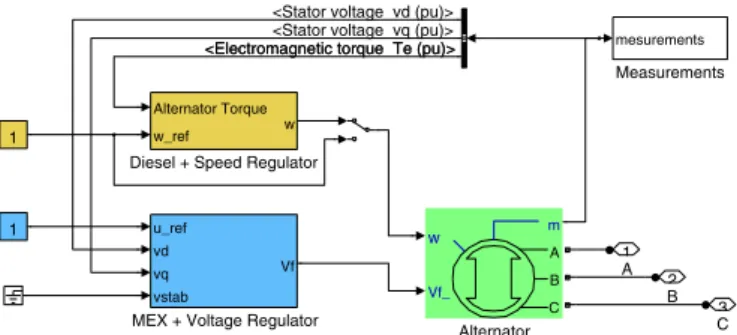
In this subsection, the performances of the SC ESS are more accurately assessed: the compensator model is integrated into the shipgrid case study simulator introduced in figure 1. In particular, this simulator computes a speed and voltage regulated diesel-alternator model that is sketched out by figure
0 5 10 15 20 25 30 35 40 45 50 55 60 600 700 800 900 1000 1100 1200 1300 1400 1500 1600 Time (s) Voltage (V) Reference DC voltage Effective DC voltage
(a) DC voltage reference and effective DC voltage 0 5 10 15 20 25 30 35 40 45 50 55 60 −200 −180 −160 −140 −120 −100 −80 −60 −40 −20 0 20 40 Time (s) Power (kW)
(b) SC ESS active power
Fig. 7. DC voltage and SC ESS active power estimated with the dedicated ESS simulator
8. Consequently the frequency modulation mitigation due to the compensator can be estimated (whereas it is impossible with the dedicated ESS simulator).
C3 B2 A 1 1 1 Measurements mesurements
MEX + Voltage Regulator
u_ref vd vq vstab
Vf
Diesel + Speed Regulator
Alternator Torque w_ref w Alternator Vf_ m A B C w
<Stator voltage vd (pu)> <Stator voltage vq (pu)> <Electromagnetic torque Te (pu)> <Electromagnetic torque Te (pu)>
Fig. 8. Diesel generator simulator with speed and voltage regulators The SC ESS model is integrated into the global shipgrid simulator depicted in figure 9. Some modifications are neces-sary as to compute the Park transform in order to synchronize the ESS AC/DC converter with the grid voltage imposed by the generator. The converter is still considered perfect: in particular (and mainly for time calculation reason), the PWM effects are not taken into account.
powergui Continuous A B C + − A B C a b c A B C a b c A B C a b c A B C a b c STRATEGY V_DC_ref Q_ref PULSE LOAD − + PASSIVE LOAD A B C INIT GRID FILTER A B C a b c GENERATOR A B C AC / DC CONVERTER V_DC_ref Q_ref A B C + −
Fig. 9. View of the complete ship grid simulator (with the SC ESS)
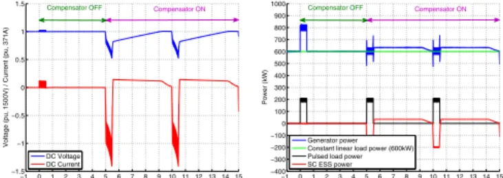
The pulsed load is activated from time0𝑠 to the end of the simulation and the SC ESS is controlled to compensate the pulsed load from time5𝑠 to the end of the simulation. Figure 10-a shows the DC voltage and DC current variations obtained with the shipgrid simulator. Both voltage and current behave as predicted. In particular, the average DC current during dis-charge is close to the value used to size the supercompensator bank (see relation (8)). The DC voltage variation complies
with the one obtained in the dedicated simulator (see figure 7-a). The SC ESS charge/discharge cycle is synchronized with the pulsed load with a smooth time advance (0.03𝑠) in order to compensate the lower power rise of the ESS in comparison with the one of the pulsed load. The benefit of this strategy is illustrated by figure 10-b that draws the power variations of the components of the grid: a satisfying dynamic balance between the ESS and the pulsed load is obtained. Figure 11-a and figure 11-b show the speed and the torque of the diesel: with the SC ESS, diesel torque and speed variations are clearly smoother and mitigated. This statement leads to a significant reduction of the frequency modulation from 0.7% to 0.2%. It can be noted that the voltage modulation complies the standard requirement with or without the SC ESS: it is lower than 1%.
−1 0 1 2 3 4 5 6 7 8 9 10 11 12 13 14 15 −1.5 −1 −0.5 0 0.5 1 1.5 Time (s)
Voltage (pu, 1500V) / Current (pu, 371A)
DC Voltage DC Current
Compensator OFF Compensator ON
(a) DC voltage and DC current (SC ESS side) −1 0 1 2 3 4 5 6 7 8 910 11 12 13 14 15 −400 −300 −200 −100 0 100 200 300 400 500 600 700 800 900 1000 Time (s) Power (kW) Generator power Constant linear load power (600kW) Pulsed load power SC ESS power
Compensator OFF Compensator ON
(b) Dynamic power sharing between the grid components
Fig. 10. DC voltage and current and grid power balance
−1 0 1 2 3 4 5 6 7 8 9 10 11 12 13 14 15 0 0.1 0.2 0.3 0.4 0.5 0.6 0.7 0.8 0.9 1 Time (s)
Diesel Torque (pu, 5.3kNm)
Compensator OFF Compensator ON
(a) Diesel torque variation
−1 0 1 2 3 4 5 6 7 8 910 11 12 13 14 15 0.99 0.992 0.994 0.996 0.998 1 1.002 1.004 1.006 1.008 1.01 Time (s) Frequency (pu, 60Hz) Standard limit
Compensator OFF Compensator ON
(b) Diesel speed (grid frequency) vari-ation
Fig. 11. Simulated diesel torque and speed variation
V. CONCLUSION
In this paper, a parallel SC ESS with SC direcly connected to the grid converter is sized and simulated to compensate a pulsed power load. The SC ESS dynamic performances are estimated by performing a simulation of a simple ship grid that integrates a voltage and speed regulated generator. The goal is to state about the frequency modulation reduction that can be obtained with the SC ESS. Regarding the SC ESS management, the DC voltage is controlled at any time and SC ESS charge and discharge are ordered by stepping the reference DC voltage to minimal value or maximal value. Furthermore SC ESS charge/discharge cycle is synchronized
with the pulsed load with a smooth time advance in order to compensate the lower power rise of the ESS in comparison with the one of the pulsed load. The results obtained with the shipgrid simulator are convincing: the frequency modula-tion is significantly reduced (by more than three times) and becomes compliant with the standard requirement. Regarding the generator side, the governor torque variations are strongly mitigated.
These results must be reinforced. The supercapacitor model could be improved in order to capture the non linear rise and fall of the voltage. Concerning the SC ESS topology, it would be interesting to compare the present topology with the more usual topology that integrates a chopper between the DC bus and the SC: SC sizing and control would be different. In this paper a parallel compensator is wanted in order to use it for other functions as reactive power compensation and voltage sag mitigation for example. The possibility of performing these aditionnal functions should be clearly stated by further simulations which probably leads to modify the control strategy of the SC ESS.
REFERENCES
[1] “Characteristics of shipboard low voltage electrical power systems in warships of the nato navies,” NATO Standardisation Agreement STANAG 1008, ed.9, August 2004.
[2] M. Steurer, M. Andrus, J. Langston, L. Qi, S. Suryanarayanan, S. Woodruff, and P. Ribeiro, “Investigating the impact of pulsed power charging demands on shipboard power quality,” in Electric Ship
Tech-nologies Symposium, 2007. ESTS ’07. IEEE, May 2007, pp. 315 –321.
[3] F. Scuiller, “Simulation of an energy storage system to compensate pulsed loads on shipboard electric power system,” in Electric Ship
Technologies Symposium (ESTS), 2011 IEEE, april 2011, pp. 396 –401.
[4] SimPowerSystem References, Online only ed., The MathWorks, Inc., September 2007.
[5] S. Kulkarni and S. Santoso, “Impact of pulse loads on electric ship power system: With and without flywheel energy storage systems,” in
Electric Ship Technologies Symposium, 2009. ESTS 2009. IEEE, 2009,
pp. 568 –573.
[6] R. S. Weissbach, G. G. Karady, and R. G. Farmer, “Dynamic voltage compensation on distribution feeders using flywhell energy storage,”
IEEE Transactions on Power Delivery, vol. 14, no. 2, pp. 465–471,
April 1999.
[7] H. Toliyat, S. Talebi, P. McMullen, C. Huynh, and A. Filatov, “Advanced high-speed flywheel energy storage systems for pulsed power applica-tions,” in Electric Ship Technologies Symposium, 2005 IEEE, 25-27 July 2005, pp. 379–386.
[8] I. Galkin, A. Stepanov, and J. Laugis, “Outlook of usage of supercapaci-tors in uninterruptible power supplies,” in Baltic Electronics Conference,
2006 International, oct. 2006, pp. 1 –4.
[9] S. Smith and P. Sen, “Ultracapacitors and energy storage: Applications in electrical power system,” in Power Symposium, 2008. NAPS ’08. 40th
North American, sept. 2008, pp. 1 –6.
[10] L. Shi and M. Crow, “Comparison of ultracapacitor electric circuit models,” in Power and Energy Society General Meeting - Conversion
and Delivery of Electrical Energy in the 21st Century, 2008 IEEE, july
2008, pp. 1 –6.
[11] Y. Wang, “Modeling of ultracapacitor short-term and long-term dynamic behavior,” August 2008.
[12] “Bc series ultracapacitor, datasheet,” on Maxwell Technology website http://www.maxwell.com, March 2012.