Science Arts & Métiers (SAM)
is an open access repository that collects the work of Arts et Métiers Institute of Technology researchers and makes it freely available over the web where possible.
This is an author-deposited version published in: https://sam.ensam.eu
Handle ID: .http://hdl.handle.net/10985/9938
To cite this version :
Romain PIQUARD, Alain D'ACUNTO, Pascal LAHEURTE, Daniel DUDZINSKI - Micro-end milling of NiTi biomedical alloys, burr formation and phase transformation - Precision Engineering - Vol. 38, n°2, p.356-364 - 2014
Any correspondence concerning this service should be sent to the repository Administrator : archiveouverte@ensam.eu
Micro-end milling of NiTi biomedical alloys, burr formation and phase
transformation
R. Piquard, A. d’Acunto, P. Laheurte, D. Dudzinski 5
LEM3 UMR CNRS 7239 Arts et Métiers ParsTech
Université de Lorraine
4, Rue Augustin Fresnel, 57070 Metz-France 10
Keywords: NiTi shape memory alloys, micro-milling, burrs, phase transformation ABSTRACT
15
This paper focuses on burr formation in micro-end milling of two Nickel-Titanium shape memory alloys (SMA), an austenitic and a martensitic NiTi. Phase transformation during machining was also examined.
The experimental design approach was used to study the effect of cutting parameters on burr formation. The studied parameters were cutting speed, feed per tooth, depth and width of cut, 20
machining strategy and initial material phase of the NiTi alloy. Different types of burrs were formed during micro-end milling of NiTi alloys; it was observed that top burrs are the most important. The height of top burrs can reach values close to those of the depth of cut. Burrs were observed and characterized using a Scanning Electron Microscope (SEM), confocal and optical microscopes. The affected layer under the machined surface, and phase transformation 25
were investigated by using SEM.
The results of the analysis of variance showed a significant formation of burrs, deeply influenced by the feed per tooth and width of cut. An increase in the feed per tooth and a decrease of width of cut tend to decrease the height and width of the top burr. In a thin layer under the machined surface, phase transformation was observed for the martensitic NiTi. 30
1. Introduction
Shape memory alloys (SMA's) are metals, which exhibit two very unique properties, pseudoelasticity and the shape memory effect (SME). The Nickel-Titanium (NiTi) alloys are one type of these materials; they present additional advantages such as biocompatibility, high 35
ductility, high strength to weight ratio, good fatigue and corrosion resistance, high damping capacities[1]. Due to their properties, NiTi alloys are used in medical, dental and micro-mechanics applications.
The high ductility, the high degree of strain hardening of NiTi alloys, their unconventional strain-stress behaviour lead them to be difficult to process, more particularly difficult to 40
machine by using conventional techniques . Shaping is therefore mostly realized by Electro discharge machining [2–4] or waterjet machining [5], or laser machining [6]. A recent paper of M.H. Elahinia [7] gives a large review of manufacturing and processing of NiTi parts. As pointed by Lin et al. [2], these special machining techniques have some technical limits and study and understand the conventional machining characteristics of NiTi SMAs remains an 45
important goal.
Wu et al. [1] presented a first investigation on the machinability of a NiTi shape memory alloy. By using a mechanical cutting test, they compared the behaviour of three different materials: a NiTi alloy, a 304 stainless steel and a TiAl intermetallics. The mechanical cutting tests were carried out by using a precision saw with a diamond blade with a rotation speed 50
and an applied load digitally controlled. Due to their high ductility, some adhering cut fragments of NiTi alloy and 304 stainless steel were observed on the blade. For a same cutting area, the cutting time was greater for these two materials. In addition, the authors measured the hardness profile in the machined subsurface. The NiTi exhibited a severe hardening effect near the machined surface. By using scanning electron microscope, ploughing grooves and 55
deposited worked material fragments were observed on the NiTi machined surface. A similar study was performed by Lin et al, [2] they compared the machining characteristics of two NiTi alloys during the same mechanical cutting test as previously, but also during drilling tests.
The machinability of NiTi shape memory alloys was also examined by Weinert and Petzoldt 60
[8], [9], with turning and drilling experiments. The turning tests concerned a β-NiTi alloy, performed under dry and wet conditions for various cutting speed values. According to their experimental results, the authors proposed to distinguish three stages to describe the machinability of this alloy. At low cutting speeds (≤60m/min), the cutting forces were very
high and as a consequence the tool wear was elevated with a high notch wear. Using emulsion 65
as lubricant reduced cutting forces and tool wear only for the lowest cutting speed value of 20m/min. In the second stage (60 ≤ VC ≤ 130m/min), the cutting forces and the tool wear appeared to be unaffected by the cutting speed value and by the cutting fluid. In the third range (VC >130m/min), the cutting forces and the tool wear increased significantly for dry conditions. Due to its high ductility, a large burr formation occured when machining NiTi 70
alloys. At the beginning of the cutting process, the width of the burr was less than the feed rate and then it increased rapidly to attain higher values. In the same way, the height of burr might grow up to several millimetres. They found that the cutting depth should be limited to the tool cutting edge radius. When the cutting depth exceeded the cutting edge radius high notch wear occured. It must be noted that a poor chip breaking was an additional problem 75
when turning TiNi alloy. After turning tests, drilling and deep drilling were performed. Low cutting speed and high feed caused an increase of the microhardness in the machined subsurface due to workhardening.
Micro-end milling of a β-NiTi shape memory alloy was then examined by Weinert and Petzoldt [10]. The cutting tools were solid carbide end milling cutters with a diameter of 80
0.4mm; all the tools were coated with a TiAlN layer. The machining tests were performed both under dry and wet conditions with an ester oil for minimum quantity lubrication (MQL). In a first step, the cutting forces were measured, and it was noted that when applying a width of cut of ae= 40µm, the passive axial force was very high in comparison with the active force (cutting and feed components). Surface quality and the tool condition were then examined for 85
optimal cutting conditions. It was demonstrated that in comparison to dry machining, MQL reduces the NiTi-adhesions and the flank wear on the end milling cutter. Under MQL, high surface quality was obtained; however large burr formation was observed. The burr formation can be reduced by increasing radial engagement ae and depth of cut ap to 20 µm, but an increasing of depth of cut leads to a radial deflection of the tool depicted by scanning the 90
machined surface topography.
Taking into account of its low thermal influence on phase transformation temperatures of NiTi SMAs, Biermann et al. [11] pointed on the advantage of machining by micro-milling. Five-axis ball end micro-milling tests with various tool inclinations were performed; and, micro deep-hole drilling experiments were discussed. TiAlN coated cemented carbide ball 95
end mills with a diameter of 1.0 mm were used. A simulation algorithm was proposed to optimize tool inclination; it was based on the geometric analysis of the various engagement of the cutting edge
In this paper, the focus is on burr formation in micro-end milling of an austenitic and of a martensitic NiTi alloys. After a brief review giving an overview of burr formation in 100
machining and machining, an experimental investigation of burr formation in micro-end-milling is presented. The influence of cutting conditions is particularly studied on the size of the observed top burrs. In addition, the affected layer and phase transformation under the machined surface were explored. The machining tests were performed by following the Design of experiments approach and the results are discussed using analysis of variance. 105
2. Burr formation, a brief review
The definition but also the description of burrs are not unique, they depend strongly on the machining process, mechanical properties of the work material or their type of formation. In this study, a burr is considered as an accumulation of material on the edges of a workpiece. 110
According to Gillespie [12], three different mechanisms of burr formation can occur:
• Poisson burr: the material is bulged on the free surfaces, due to high compression and plastic deformation;
• Tear Burr: comes from the removal of the chip on the piece, similar to punching burrs; • Rollover Burr: due to bending of the material, often the last chip on the exit surfaces which 115
is still attached.
Other formation mechanisms exist but lead to a lack of material at the edge (due to crack propagation).
Fig. 1 : The three main mechanisms of burr formation [12], [13]
120
These mechanisms do not necessarily occur on all edges of the workpiece. In face milling, eight burr locations were identified by Hashimura et al. [14]; entrance and exit burrs, top and side burrs are distinguished. This classification is included in the following of this paper, in Fig. 5.
Weinert and Petzoldt [8] proposed a qualitative model of burr formation in turning NiTi alloy, the geometry of top burrs was defined by two parameters, the height and width of burr (respectively hb and wb). Depending on the relative value of the burr width with respect to the feed rate, two stages were distinguished. In the first one, the width of the burr is smaller than 130
the feed that conducts to a full removal of burr at each workpiece rotation. For the second stage, the width of burr is larger than feed, conducting to a partial removal of burr at each workpiece rotation and adding a burr growth by bulging of material. It was observed that the transition from stage 1 to stage 2 is due to an increase of tool wear.
135
Olvera and Barrow [15] presented a study on burr formation in square shoulder milling of AISI 1040 steel. The results of experimental study showed that a decrease of feed per tooth leads to an increase of top burr height and that for down-milling, the height of burr decreases more steeply than in up-milling.
140
Lee and Dornfeld [13] proposed to minimize burr formation through the cutting speed and feed per tooth in the case of stainless steel by machining holes using micro-mills. The lifetime was defined as the number of machined holes before a sudden increase of the height of burrs. With the results of this work, the height of burr appears to decrease with a decrease of the cutting speed and an increase of the feed per tooth.
145
Lekkala et al. [17] presented a study on burr formation in micro-milling of slots using the design of experiments approach and analysis of variance. Factors studied were the diameter of the tool, the axial engagement, the number of teeth, the spindle speed, feed rate and feed rate×number of teeth interaction. The studied responses were the height and thickness of burrs in a stainless steel and an aluminum alloy. For a 95% significance level, burr height was 150
influenced by tool diameter, axial engagement, number of teeth, feed rate, and the considered interaction. An increase in feed rate tended to decrease the height of burrs. In up-milling, burrs seemed torn. Finally, the author proposed an analytical modelling (physical and geometrical) of the height of exit burrs based on the continuity of the mechanical work and presented results in agreement with experimental results with an accuracy between 0.65 and 155
25%.
3.1.Work materials 160
The machined materials were a martensitic and an austenitic NiTi shape memory alloys (SMA). As pointed out by Kong et al. [5], phase transformation plays a major role in the behaviour of a NiTi shape memory alloy (SMA). The ability of NiTi alloys to recover large amounts of plastic strain is due to the martensitic phase transformation initiated at certain 165
conditions of stress and temperature.
The characteristic temperatures transformations of the two machined materials were measured in Differential Scanning Calorimetry (DSC) apparatus where the specimens were subjected to a complete thermal cycle (heating and cooling) between -120 °C and +120 °C with a rate of 10 °C/min. From the DSC curves, the transformation start and finish temperatures were 170
determined by the intersection of a base line and the tangent to a peak, Fig. 2. The R-phase is a martensitic intermediate phase in the Martensite-Austenite transformation of the NiTi alloy.
Fig. 2 : DSC curves for (a) austenitic NiTi; (b) martensitic NiTi.
Tab. 1 : Characteristic temperatures transformations of the two machined materials measured in DSC
175
apparatus.
Materials Ms (°C) Mf (°C) As (°C) Af (°C) Rf (°C)
Martensitic NiTi 40.3 15.4 59 84.5
As the transformation temperatures and stresses are linked, martensite ↔ austenite transformation may occur for the two NiTi alloys during machining depending on stresses and temperature of cutting process.
180
3.2.Experimental set-up
Milling tests were performed on a Röders RXP 200DS CNC (3,000 - 60,000 rpm) 5-axis high speed machining center. Tools used were referenced by NS TOOL as MX 225 with a diameter of 0.8 mm, two teeth, a helix angle of 25° and a TiAlN coating. The machining 185
procedure followed these steps:
- After a spindle warm-up of 30 minutes, the specimen was surfaced to get the upper plane (reference for the depth of cut) with an end mill (Hitachi HYPS 2020) with a diameter of 2 mm, by sweeping along the Y-axis of the machine tool. Before machining, the tool was measured by the laser system of the CNC.
190
- Slots were machined along the Y-axis with a milling cutter with a diameter of 0.8 mm with full diameter engagement and a depth of 200 µm by Z-levelling steps of 10 µm. - After another warm-up of 30 minutes, the cutting tests were performed on the sides of
the previous slots (shouldering), with the operating conditions proposed in the design of experiments. Before any change of cutting speed value, the spindle was again 195
submitted to a warm-up.
Spindle warm-up was necessary to reduce thermal expansion and thus to control the depth of cut. In order to minimize the tool wear effect on burr formation, the tool was changed after machining four square shoulders. Following Weinert and Petzoldt [10], MQL was applied. A minimum volume of an ester oil (1.6 ml/min) mixed with compressed air (6 bar) was fed to 200
the cutting zone.
3.3.Experiment design
Design of experiments approach (DOE) was employed to study burr formation during micro-milling of TiNi alloys. The input parameters were the cutting conditions and the work 205
materials; the output parameters were the geometrical characteristics of the produced burrs. With Weinert and Petzoldt [10] and following previous works reported in Aurich et al. [11], the burr geometry was defined in its cross-sectional profile, Fig. 3; and described by the following parameters:
The burr height hb defined by the distance between the workpiece surface and the 210
highest point in the cross sectional section;
The burr thickness tb measured above the burr root; The total burr width wb.
The observation and measurement of burrs after micro-milling correspond to a long process and the DOE approach was justified to reduce the number of cutting tests.
215
Fig. 3 : Geometrical characteristics of burr defined in its cross-sectional profile
A half factorial design was used for input parameters which were the depth of cut ap, width of cut ae, cutting speed Vc, feed per tooth fz, strategy (up and down-milling) and material phase. The associated low and high levels of these parameters are listed in Tab. 2. The selected 220
values were chosen to cover a range around the cutting conditions used in previous works and briefly presented in the introduction. In addition to the effects of input parameters on burr formation, six interactions were studied:
- Material phase and cutting speed, - Material phase and depth of cut, 225
- Material phase and feed per tooth, - Feed per tooth and width of cut, - Strategy and width of cut,
These interactions might be influent on burr formation, due to: (1) the dependency of cutting 230
conditions on work material (for the first three interactions), (2) the possible effect of the cross section of uncut chip (for the fourth and fifth ones), and (3) the variation of cutting forces and chip flow rate during the cutting process (for the last interactions). Thus the model considered can be written:
𝑦 = 𝑀 + +𝐸𝐼− 𝐸𝐼+ . 𝐼 𝐼 + 𝐼 𝑡 𝐸𝐼−𝐽 − 𝐸𝐼−𝐽 + 𝐸𝐼+𝐽 − 𝐸𝐼+𝐽 + 𝐽 𝐼,𝐽 + 𝐼 𝑡 𝐸𝐼−𝐽 −𝐾− 𝐸𝐼−𝐽 +𝐾− 𝐸𝐼+𝐽 −𝐾− 𝐸𝐼+𝐽 +𝐾− 𝐽 𝐼 𝑡 𝐸𝐼−𝐽 −𝐾− 𝐸𝐼−𝐽 +𝐾− 𝐸𝐼+𝐽 −𝐾− 𝐸𝐼+𝐽 +𝐾− 𝐽 𝐾 𝐼,𝐽 ,𝐾 (1) 235
Where𝑦 is the theoretical response, M is the average, [I] the vector associated to a parameter which is equal to 10 when the parameter is at the lowest level and to 01 when it is at the highest level, EI is the effect of the parameter I (the sign giving the level), EIJ and EIJK are the effect of interactions.
Tab. 2 : input parameters and their associated levels
240
Parameters Level - Level +
Strategy Up-milling Down-milling
Depth of cut (µm) 50 100
Cutting speed (m/min) 30 60
Material NiTi austenitic martensitic
Feed per tooth (µm/tooth) 6 12
Width of cut (µm) 100 200
Results were analysed based on analysis of variance (ANOVA) and Fisher-Snedecor test for a significance level of 95%. In order to find the appropriate array and to analyse rapidly the results, the software Nemrodw® was used.
An experimental 26-2 array (16 experiments) shown in Tab. 3, with 1 repetition for a total of 245
32 experiments, was chosen in order to improve the level of confidence with a limited number of experiments.
Tab. 3 : Detail of the 26-2 array of design of experiments
N°Exp Strategy Depth of cut Cutting speed Material Feed per tooth Width of cut
µm m/min µm µm
1 Up-milling 50 30 Austenite 12 100
2 Down-milling 50 30 Austenite 6 100
3 Up-milling 100 30 Austenite 6 200
5 Up-milling 50 60 Austenite 12 200 6 Down-milling 50 60 Austenite 6 200 7 Up-milling 100 60 Austenite 6 100 8 Down-milling 100 60 Austenite 12 100 9 Up-milling 50 30 Martensite 12 200 10 Down-milling 50 30 Martensite 6 200 11 Up-milling 100 30 Martensite 6 100 12 Down-milling 100 30 Martensite 12 100 13 Up-milling 50 60 Martensite 12 100 14 Down-milling 50 60 Martensite 6 100 15 Up-milling 100 60 Martensite 6 200 16 Down-milling 100 60 Martensite 12 200 3.4.Burr characterization 250
Concerning burr measurements, average height of burrs was measured using white light confocal interferometer Leica DCM3D; width was measured using Scanning Electron Microscope Jeol JSM-7001F; and thickness using optical microscope Zeiss Axio Imager M1m after polishing entrance surface, Fig. 4. Height and width can also be measured with 255
optical microscope, but these values are representative of a specific section; with the two other measurement systems, an average dimension was found along the square shoulder.
260
Fig. 4 : Three measurement systems
4. Results and discussions
4.1.Preliminary observations
After performing the milling tests of the design of experiments, the machined samples were 265
first observed with Scanning Electron Microscope. Locations and size of burrs were identified. Twelve locations were distinguished; Fig. 5 gives an example of burrs obtained
during experiments 3 and 4. They correspond to the eight locations described by Hashimura [14]; in addition up-milling and down-milling entrance and entrance side burrs were differentiated; and tip burrs were added. Tip burrs may be related to exit burr for cutting 270
direction according to Olvera and Barrow [15], they are created by the end-mill tip on the lowest edge of the square shoulder. Top burrs (4 and 10), exit side burr in down milling (5) and entrance side burr in down milling (8) are the most significant. Top burrs obtained in up-milling (4) present a large curvature; whereas top burrs obtained in down-up-milling (10) are lightly bent. Moreover, top burrs in up-milling (4) are torn along the edge, and those in down-275
milling (10) are continuous with cracks on the top. From the preliminary observations, it appeared that the top burrs were mostly affected by the parameters of DOE, whereas the exit side burrs and entrance side burrs which were only dependent of strategy. That was the reason why only top burr were studied in the DOE.
Fig. 5 : Entrance and exit of tests n°3 and n°4
End-mills were then observed after machining four square shoulders, using SEM with EDS analysis, to verify that tool wear was negligible. Fig. 6 shows a representative tool wear 285
pattern on rake face. The dimensions of the wear zone where the tungsten are about 100µm length along the cutting edge and approximately 10µm width corresponding to the upper levels of depth of cut and feed per tooth. It can be observed that the coating has been removed in a large part of this zone and that nickel and titanium elements are present on tool rake face,
representative of a slight alloy deposition; however, not any cutting edge degradation is 290
depicted and it may be confirmed that the tool life limit had not been reached.
Fig. 6: EDS analysis of tool wear and material deposit
4.2.Effect on microstructure 295
For the austenitic NiTi, no modification of the microstructure in the subsurface is visible on the Fig. 7a. Only stress induced martensite is observed in all the sample thickness; sign of important plastic deformation during the initial forming process (drawing). Stress induced martensite was also generated during the machining process as it can be seen in 300
Fig. 7a, just below the machined surface (about 10 µm).
For the martensitic NiTi sample (Fig. 7b), there is a zone of approximately 20 µm under the machined surface which was affected by a martensite - austenite phase transformation due to the heating during the machining process; that means that no return to the martensitic state after cooling occurred. These observations were confirmed by Knoop 305
hardness measurements in the machined under layer and in the core of the sample; the austenite being harder than martensite (190 ± 4 HK and 245 ± 5 HK, respectively).
Fig. 7: Cross sections of the two specimens (a) Austenitic NiTi, (b) Martensitic alloy; and microstructure
310
after machining.
4.3.Results of DOE
The quantitative characterization of burr formation through the burr cross-sectional profile description (parameters hb, wb and tb), and based on the results of DOE using analysis of 315
variance are now discussed. The results of ANOVA are presented on Tab. 4 (a), (b) and (c); for each parameter and each chosen interaction, the statistics are given through the average value M, the effect value (corresponding to the highest level), the significance of the parameter and its probability P of being not significant. Normality is verified by plotting standard deviations versus residual values, Fig. 8. The plots are arranged approximately along 320
a straight line this means that residuals follow a normal distribution.
Tab. 4 : ANOVA for burr dimensions
325
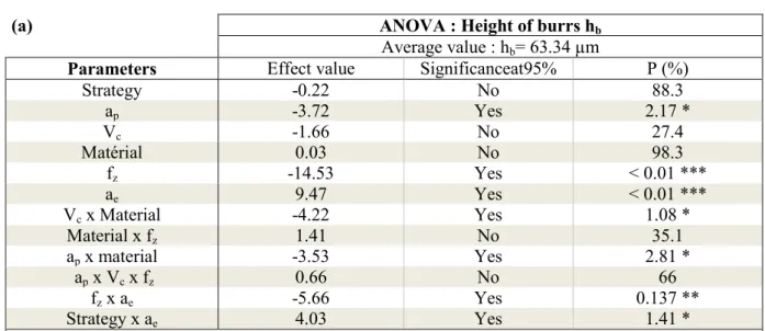
(a) ANOVA : Height of burrs hb
Average value : hb= 63.34 µm
Parameters Effect value Significanceat95% P (%)
Strategy -0.22 No 88.3 ap -3.72 Yes 2.17 * Vc -1.66 No 27.4 Matérial 0.03 No 98.3 fz -14.53 Yes < 0.01 *** ae 9.47 Yes < 0.01 *** Vc x Material -4.22 Yes 1.08 * Material x fz 1.41 No 35.1 ap x material -3.53 Yes 2.81 * ap x Vc x fz 0.66 No 66 fz x ae -5.66 Yes 0.137 ** Strategy x ae 4.03 Yes 1.41 *
*: significance from 95% to 99%; **: significance from 99% to 99,9%; ***: significance over 99,9%
(b) ANOVA : Width of burrs wb
Average value : wb= 65.87 µm
Parameters Effect value Significanceat 95% P (%)
Strategy -6.19 Yes 0.0129 *** ap 0.37 No 76.5 Vc -0.56 No 65.5 Matérial -3.5 Yes 1.20 * fz -10.06 Yes < 0.01 *** ae 10.56 Yes < 0.01 *** Vc x Material 1.94 No 13.7 Material x fz -0.69 No 58.6 ap x material -4 Yes 0.516 ** ap x Vc x fz -1 No 43 fz x ae -7.25 Yes < 0.01 *** Strategy x ae -2.75 Yes 4.08 *
*: significance from 95% to 99%; **: significance from 99% to 99,9%; ***: significance over 99,9%
(c) ANOVA : Thickness of burrs tb
Average value : tb= 7.22 µm
Parameters Effect value Significanceat 95% P (%)
Strategy 2.22 Yes < 0.01 *** ap -0.84 Yes 0.0806 *** Vc 1.47 Yes < 0.01 *** Matérial 1.72 Yes < 0.01 *** fz -0.72 Yes 0.292 ** ae -0.97 Yes 0.0228 *** Vc x Material 0.34 No 11.3 Material x fz 0.41 No 6.5 ap x material -0.34 No 11.3 ap x Vc x fz -0.16 No 45.7 fz x ae -0.41 No 6.5 Strategy x ae -0.84 Yes 0.0806 ***
For the height of burr hb, Tab. 4 (a), three parameters are influent, the depth and the width of cut and the feed per tooth, and four main interactions are found, cutting speed Vc × material, 330
depth of cut ap × material, feed per tooth fz × width of cut ae, and width of cut ae × strategy. Moreover, more than 60% of the total effects of significant factors are only represented by the effects of feed per tooth fz, width of cut ae and their interaction. An increase (from low values to high values) of depth of cut and feed per tooth leads to a decrease of burr height of about 7 and 29 µm respectively (theoretically 7.44µm and 29.06 µm); whereas an increase of width of 335
cut implies an increase of burr height of about 19µm. The significant interaction between these two parameters indicates that the positive effect (increase of height of burr) of width of cut is greater when feed per tooth fz is equal to 6 µm than for a value of 12 µm. Fig. 9 gives a graphic view of the main parameters and interaction effects.
340
Fig. 9 : height of burr for low and high values of parameter, and for the combined values of depth and width of cut.
For the width of burrs wb, Tab. 4 (b), the main effects are obtained for feed per tooth fz and width of cut ae (almost 50% of total effects). An increase of feed per tooth leads to a decrease 345
of burr width of about 20 µm; whereas an increase of width of cut implies an increase of burr width of 21 µm. The interaction between these two parameters is also highly significant and its effect is very similar that the one obtained for height of burrs. The effect of machining strategy confirms the preliminary observations on the shape of top burrs. Wider top burrs are obtained in up-milling. Wider burrs are obtained with the austenitic NiTi alloy than with the 350
Fig. 10 : width of burr for low and high values of parameter, and for the combined values of feed per tooth and width of cut.
355
For the thickness of burrs tb, Tab. 4(c), all the parameters give significant effects, and the main interaction is between machining strategy and width of cut ae. Machining strategy seems to be the most significant parameter; in comparison to burrs in up-milling, those in down-milling are thicker of 4 µm. An increase of cutting speed (from low to high value) leads to thicker burrs of about 3 µm; in opposite an increase of the depth of cut ap, or feed per tooth fz 360
or width of cut ae leads to decrease of burr thickness in lower proportions.
The interaction between strategy and width of cut shows that an increase of width of cut ae in up-milling doesn’t affect burr thickness; in down-milling an increase of width of cut ae tends to a significant decrease of burr thickness. A graphic view of these effects is shown on Fig. 365
Fig. 11 : burr thickness for low and high values of parameter, and for the combined values of strategy and width of cut.
370
Fig. 12 gives a summary of previous results. The three geometrical characteristics of burrs (height, width and thickness) are greatly influenced by feed per tooth and width of cut and to a lesser extent by the interaction between strategy and width of cut. Strategy and material phase have similar effects on width and thickness of burrs; in the same way, the interaction between depth of cut and material phase (ap × material) and the interaction between feed per 375
tooth and width of cut (fz × ae) have comparable effects on burr height and width. Depth of cut has a moderate effect on height and thickness of burr. Interaction between material phase and feed per tooth and between depth of cut (ap × Vc × fz), and interaction between material phase and feed per tooth (Material × fz) are not significant.
380
Considering the model given by equation (1), and only the influent parameters, the three responses can be written as:
ℎ = 63.34 + +3.72 −3.72 . 𝑎𝑏 𝑝 + +14.53 −14.53 . 𝑓𝑧 + −9.47 +9.47 . 𝑎𝑒 + 𝑉𝑐 𝑡 −4.22 +4.22+4.22 −4.22 𝑀𝑎𝑡𝑒𝑟𝑖𝑎𝑙 + 𝑎𝑝 𝑡 −3.53 +3.53+3.53 −3.53 𝑀𝑎𝑡𝑒𝑟𝑖𝑎𝑙 + 𝑓𝑧 𝑡 −5.66 +5.66 +5.66 −5.66 𝑎𝑒 + 𝑆𝑡𝑟𝑎𝑡𝑒𝑔𝑦 𝑡 +4.03 −4.03−4.03 +4.03 𝑎𝑒 (2) 𝑤 = 65.87 + +6.19 −6.19 . 𝑆𝑡𝑟𝑎𝑡𝑒𝑔𝑦 + +3.5 −3.5 . 𝑀𝑎𝑡𝑒𝑟𝑖𝑎𝑙 + +10.06 −10.06 . 𝑓𝑏 𝑧 + −10.56 +10.56 . 𝑎𝑒 + 𝑎𝑝 𝑡 −4 +4+4 −4 𝑀𝑎𝑡𝑒𝑟𝑖𝑎𝑙 + 𝑓𝑧 𝑡 −7.25 +7.25+7.25 −7.25 𝑎𝑒 + 𝑆𝑡𝑟𝑎𝑡𝑒𝑔𝑦 𝑡 −2.75 +2.75+2.75 −2.75 𝑎𝑒 (3) 385
𝑡 = 7.22 + −2.22 +2.22 . 𝑆𝑡𝑟𝑎𝑡𝑒𝑔𝑦 + +0.84 −0.84 . 𝑎𝑏 𝑝 + −1.47 +1.47 . 𝑉𝑐
+ −1.72 +1.72 . 𝑀𝑎𝑡𝑒𝑟𝑖𝑎𝑙 + +0.72 −0.72 . 𝑓𝑧 + +0.97 −0.97 . 𝑎𝑒
+ 𝑆𝑡𝑟𝑎𝑡𝑒𝑔𝑦 𝑡 −0.84 +0.84
+0.84 −0.84 𝑎𝑒
(4)
Fig. 12 : Summary of significant effects
As a concluding remark for DOE, the model summarized by the equations (2), (3) and (4), allows finding the conditions for the smaller burrs with respect to height, width and thickness 390
of burrs. A weighting is necessary to give the same importance to the three dimensions, it has been chosen to divide each parameter by its scale (100 µm for height and width, and 10 µm for thickness). Thus the parameter p to minimize is given by the equation (5):
𝑝 = ℎ𝑏+ 𝑤𝑏+ 10 × 𝑡𝑏 (5)
After a minimization process, the obtained optimal conditions for each material are given in Tab. 5. Only the depth of cut is different between in the results between the two phases. The conditions to reach the minimum for p in the austenitic phase were tested through experiment number1 (see Tab. 3) repeated twice. The obtained burrs are shown on Fig. 13. It seems that top burrs are fragile with a large amount of cracks.
400
Tab. 5 : minimization of burr geometrical characteristics
Material Strategy Depth of
cut Cutting speed Feed per tooth Width of cut Austenite ℎ𝑏𝑚𝑖𝑛𝑖= 45 µm 𝑤𝑏𝑚𝑖𝑛𝑖= 57.3 µm 𝑡𝑏𝑚𝑖𝑛𝑖= 1.9 µm Up-milling 50 µm 30 m/min 12 µm 100 µm Martensite ℎ𝑏𝑚𝑖𝑛𝑖= 46 µm 𝑤𝑏𝑚𝑖𝑛𝑖= 47.7 µm 𝑡𝑏𝑚𝑖𝑛𝑖= 4.12 µm Up-milling 100 µm 30 m/min 12 µm 100 µm
Fig. 13 : Top burr of test n°1 (with repetition)
405
4.4.Top burr formation, a qualitative explanation
Streaks can be observed on top burrs, Fig. 14: they are very similar to shear bands found in cross section of segmented chips. However, the discontinuity of milling process suggests that these marks come from the successive passages of teeth
Fig. 14 : Zoom on top burr streaks
A possible explanation is shown in Fig. 15 where an initial burr is formed on the curved generated surface, for the considered tool revolution, by the flank cutting edge. This burr is bulged material due to high compressive stresses when the uncut chip thickness is small; and 415
this effect is increased by the tool helix angle leading to an oblique cutting process. The final burr corresponds to the accumulation of successive small burrs formed at each tool passage (half revolution for a two teeth tool).
Following this idea, the length of the burr formed by bulging is a function of the length of contact between material and tooth, thus to width of cut; as a consequence the height of burr 420
increases with the width of cut. Concerning the effect of feed per tooth fz, greater is the feed at each tooth passage, larger the part of burr created by the previous tooth is deleted. This effect was explained by Weinert [8] for turning operations. The results of DOE confirm the strong effect on width and height of burrs of width of cut ae and feed per tooth fz.
425
Fig. 15 : Formation of top burr
5. Conclusions
Burr formation in micro-end milling of an austenitic and of a martensitic NiTi alloys was studied in this paper through an experimental approach. Burrs were observed using SEM, 430
confocal and optical microscopes. The classification of burrs by their locations can be applied to micro-end milling. In comparison with other burrs (in particular entrance, exit and tip burrs), top burrs are predominant; their size is very close to the shoulder one.
The influence of cutting conditions on the size of the observed top burrs was particularly studied. In addition, the affected layer and phase transformation under the machined surface 435
were explored.
Design of experiments and analysis of variance permitted to focus on the dependency of burr dimensions to cutting conditions:
- Concerning height and width of burr, a strong dependency to feed per tooth and width of cut is coherent with the model described in the last section. Indeed, an increase of fz 440
and a decrease of ae lead to smaller burrs. Wider burrs are obtained in up-milling, with a characteristic curly shape.
- Concerning thickness, the most influent parameter is strategy. Up-milling tends to have thinner burrs. Comparing the two phases of NiTi, martensite has a most important trend to form thick burrs.
445
A minimization of burr formation would make deburring easier. In this way, an optimization of the parameters values gives the best one to minimize burr dimensions.
6. References
450
[1] S. . Wu, H. . Lin, and C. . Chen, “A study on the machinability of a Ti49.6Ni50.4 shape memory alloy,” Materials Letters, vol. 40, no. 1, pp. 27-32, Jul. 1999.
[2] H. C. Lin, K. M. Lin, and Y. C. Chen, “A study on the machining characteristics of TiNi shape memory alloys,” Journal of Materials Processing Technology, vol. 105, no. 3, pp. 455
327–332, 2000.
[3] W. Theisen and A. Schuermann, “Electro discharge machining of nickel–titanium shape memory alloys,” Materials Science and Engineering: A, vol. 378, no. 1, pp. 200–204, 2004.
[4] S. F. Hsieh, S. L. Chen, H. C. Lin, M. H. Lin, and S. Y. Chiou, “The machining 460
characteristics and shape recovery ability of Ti–Ni–X (X= Zr, Cr) ternary shape memory alloys using the wire electro-discharge machining,” International Journal of Machine Tools and Manufacture, vol. 49, no. 6, pp. 509–514, 2009.
[5] M. C. Kong, D. Axinte, and W. Voice, “Challenges in using waterjet machining of NiTi shape memory alloys: An analysis of controlled-depth milling,” Journal of Materials 465
Processing Technology, vol. 211, no. 6, pp. 959–971, 2011.
[6] N. Uppal and P. S. Shiakolas, “Micromachining characteristics of NiTi based shape memory alloy using femtosecond laser,” Journal of manufacturing science and engineering, vol. 130, no. 3, 2008.
[7] M. H. Elahinia, M. Hashemi, M. Tabesh, and S. B. Bhaduri, “Manufacturing and 470
processing of NiTi implants: A review,” Progress in Materials Science, 2011.
[8] K. Weinert and V. Petzoldt, “Machining of NiTi based shape memory alloys,” Materials Science and Engineering: A, vol. 378, no. 1, pp. 180–184, 2004.
[9] K. Weinert, V. Petzoldt, and D. Kötter, “Turning and drilling of NiTi shape memory alloys,” CIRP Annals-Manufacturing Technology, vol. 53, no. 1, pp. 65–68, 2004.
475
[10] K. Weinert and V. Petzoldt, “Machining NiTi micro-parts by micro-milling,” Materials Science and Engineering: A, vol. 481, pp. 672–675, 2008.
[11] D. Biermann, F. Kahleyss, E. Krebs, and T. Upmeier, “A Study on Micro-Machining Technology for the Machining of NiTi: Five-Axis Micro-Milling and Micro Deep-Hole Drilling,” Journal of materials engineering and performance, vol. 20, no. 4, pp. 745–751, 480
2011.
[12] L. K. Gillespie, Deburring and edge finishing handbook. SME, 1999.
[13] K. Lee and D. A. Dornfeld, “Micro-burr formation and minimization through process control,” Precision Engineering, vol. 29, no. 2, pp. 246-252, Apr. 2005.
[14] M. Hashimura, J. Hassamontr, and D. Dornfeld, “Effect of in-plane exit angle and 485
rake angles on burr height and thickness in face milling operation,” Journal of
Manufacturing Science and Engineering-Transactions of the Asme, vol. 121, no. 1, pp. 13-19, Feb. 1999.
[15] O. Olvera and G. Barrow, “An experimental study of burr formation in square
shoulder face milling,” International Journal of Machine Tools and Manufacture, vol. 36, no. 490
9, pp. 1005–1020, 1996.
[16] G. M. Schueler, J. Engmann, T. Marx, R. Haberland, and J. C. Aurich, Burr Formation and Surface Characteristics in Micro-End Milling of Titanium Alloys. 2010. [17] R. Lekkala, V. Bajpai, R. K. Singh, and S. S. Joshi, “Characterization and modeling of burr formation in micro-end milling,” Precision Engineering-Journal of the International 495
Societies for Precision Engineering and Nanotechnology, vol. 35, no. 4, pp. 625-637, Oct. 2011.
[18] M. Hashimura, K. Ueda, D. Dornfeld, and K. Manabe, “Analysis of
vol. 44, no. 1, pp. 27-30, 1995. 500
[19] S. Ko and D. Dornfeld, “Analysis of fracture in burr formation at the exit stage of metal cutting,” Journal of Materials Processing Technology, vol. 58, no. 2–3, pp. 189-200, Mar. 1996.
[20] S. Ko and D. Dornfeld, “Burr formation and fracture in oblique cutting,” Journal of Materials Processing Technology, vol. 62, no. 1–3, pp. 24-36, Nov. 1996.
![Fig. 1 : The three main mechanisms of burr formation [12], [13]](https://thumb-eu.123doks.com/thumbv2/123doknet/7293176.208534/5.892.192.689.776.916/fig-main-mechanisms-burr-formation.webp)