Science Arts & Métiers (SAM)
is an open access repository that collects the work of Arts et Métiers Institute of
Technology researchers and makes it freely available over the web where possible.
This is an author-deposited version published in: https://sam.ensam.eu
Handle ID: .http://hdl.handle.net/10985/6859
To cite this version :
Jean-Philippe COSTES, Cyrille DECES-PETIT, Yusuf ALTINTAS, Pak KO - Estimated stress and friction distributions on tool rake face in the medium density fiberboard cutting process - Forest Product Journal - Vol. 53, n°11/12, p.1-8 - 2003
Estimated stress and friction
distributions on tool rake face in the
medium density fiberboard cutting process
Jean-Philippe Costes
Cyrille Decès-Petit
Yusuf Altintas
Pak Ko
he mechanics of metal cutting has been studied extensively. As a result, the design of cutting tools and the choice of machining parameters have been fairly successfully optimized. In the case of wood cutting, although there has been considerable research done, the knowl-edge that can be practically applied ap-pears pale compared to the more mature research knowledge in metal cutting.
The major work in the mechanics of wood cutting began in the 1950s by Kivimaa (1950), Franz (1958), and McKenzie (1960). McKenzie intro-duced two numbers to describe three ba-sic types of orthogonal cutting of green wood. One is the angle, which is either normal (90 degrees) or parallel (0 degrees), between the cutting edge of the tool and the cellular grain direction. The other is the angle between the
direc-tion of cutting and the grain direcdirec-tion. McKenzie and Franz further described the various types of chips that would be expected under different tool geometry and cutting conditions. These research-ers have also performed a great number of orthogonal cutting tests to study the relationship of tool forces with rake an-gle and chip thickness for several green and dry wood species. In medium den-sity fiberboard (MDF) machining, Ste-wart (1989) found good correlation be-tween cutting forces and edge recession on C2 tungsten carbide tools with
differ-ent rake angles. His results indicate that moderate rake angles between 10 and 30 degrees are optimum for C2 tungsten carbide tools. Stewart also published the results of a study involving 20 different tool materials, coatings, and surface treatments (Stewart 1991). He found that diamond (PCD) and C2 carbide have the lowest cutting forces and tool wear. More recently, Suzuki et al. (1997), in a low-speed orthogonal cut-ting study, presented the results of the effects of clearance angle and depth of cut on the machinability of MDF. From a linear cutting experiment of MDF us-ing a modif ied millus-ing machine, McKenzie et al. (1999) developed a set of equations relating the cutting forces with the feed rate and the layer density of MDF.
A finite element technique has been attempted in wood cutting studies (Holmberg 1998). However, because wood is an anisotropic material, there is a considerable challenge in modeling the influence of grain direction and the changes in material properties along the
The authors are, respectively, Adjunct Professor, ENSAM, Place du 11 aout1944, 71250 Cluny, France; Research Officer, National Research Council of Canada (NRC), Innovation Centre, 3250 East Mall, Vancouver, BC V6T 1W5, Canada; Professor, Univ. of British Co-lumbia, Mechanical Engineering Dept., 2054-2324 Main Mall, Vancouver, BC, Canada V6T 1Z4; and Senior Research Officer, NRC. This paper was received for publication in April 2002. Article No. 9485.
©Forest Products Society 2003. Forest Prod. J. 53(11/12):
Abstract
This paper presents a model of load distribution on the cutting edge of a tool during machining medium density fiberboard (MDF). A series of cutting tests was carried out with tools having designated rake face contact lengths. Utilizing the experimental data and a mechanics approach developed earlier by the third author, a model to estimate the distribution of stresses and friction on the rake face was developed. The model provides an essential step in the design and development of cutting edge geometry to prevent early edge failure and to control and reduce thermal/mechanical loading of the tool wedge.
cutting direction. Although, it is possi-ble to predict the direction of failure in solid wood, it is difficult to predict the cutting forces, due to the unpredictable variations of material properties. In Holmberg’s finite element model, he su-perimposed several layers of isotropic material with incremental mechanical properties to simulate the orthotropic structure of wood. However, the simu-lated cutting speed in the model was much lower than that in a realistic wood cutting process. MDF, which is closer to an isotropic material, can be expected to give more consistent results and is there-fore more suitable for studying the fun-damentals of wood cutting.
MDF can be assumed to have uniform material property on the surface,
al-though its hardness and density decrease rapidly toward the core. Dippon et al. (2000) presented an orthogonal cutting test strategy to extract average friction and normal forces acting on the tool. They developed a set of constants in terms of tool rake angle, layer depth (mi-cro-hardness), and feed rate for cutting MDF. These orthogonal cutting con-stants were transformed to an oblique plane of cut, allowing accurate predic-tion of cutting forces for routers having an arbitrary geometry (Engin et al. 2000). In their model, the friction and normal load on the cutting tool were considered as point loads. In the present study, the distribution of these forces on the rake face is investigated, which
could provide essential information for the design of tool edge geometry.
In this present work, tools with re-stricted tool-chip contact lengths were studied in order to map the friction and normal load distribution between the rake face and chip in machining MDF. This paper presents the results of a series of orthogonal cutting tests using tools with different contact lengths and em-pirical equations for the prediction of friction and load distributions.
Experimental set-up
Cutting tests were performed on a CNC lathe using a set of carbide tools with a 10-degree clearance angle (γ) and a 10-degree rake angle (α) on MDF discs 400 mm in diameter. The carbide tools were ground on the rake face with a 30-degree secondary rake angle (θ) and each with a different contact length
Li (Fig. 1). The tool-chip contact is ad-justed to the desired length Liby chang-ing the grindchang-ing location along the rake face. The purpose of restricting the rake face contact length is to control the con-tact of the cut chip with the rake face. Sixteen tools were ground to varying contact lengths from 0.05 mm to 1.5 mm.
The MDF discs were initially ma-chined with a peripheral recess 5 mm d e e p o n b o t h s i d e s , l e av i n g a 4-mm-wide rib in the middle (Fig. 2). For the cutting tests, the MDF disc was fixed to a metal plate, which was at-tached to the spindle of the lathe. Or-thogonal cutting was carried out on the periphery edge of the rib with the tool moving in the radial direction toward the center of the disc (Fig. 2). Since the width of the tool cutting edge is larger than 4 mm, the process is truly orthogo-nal without any side contact between the sides of the tool cutting edge and the MDF. Furthermore, for each disc, the same layers of MDF material were ma-chined. The cutting speed was set to a constant value of 4 m/sec. For each tool, eight tests were performed at different uncut chip thickness h by adjusting the feed rate (Table 1).
A three-components Kistler force dy-namometer (9257 B) was set up to mea-sure the feed force (parallel to the direc-tion of tool modirec-tion or feed) Ff, and the tangential force (normal or perpendicu-lar to the direction of tool motion) Ft. The data were collected at a rate of 2,000 samples per second and then filtered
Figure 1. — Preliminary tool grinding process.
Figure 2. — Experimental set-up in plunge turning of MDF. The tangential (Ft) and
feed (Ff) forces are measured with a Kistler Dynamometer.
Table 1. — Experimented feed rates for tool number i.
Tool no.
Tool-chip
contact length Feed rates
i Li h i 0.25= 0.25· Li h i 0.5= 0.5· Li h i 0.75= 0.75· Li h i 1= Li hi1.25= 1.25· Li h i 1.5= 1.5· Li h i 1.75= 1.75· Li h i 2= 2· Li
with a low-pass filter set at 30 Hz cut-off frequency.
Cutting force model
In metal cutting, it is possible to ex-press the forces on the rake face as a function of the shear stress, the average tool-chip contact friction, and shear an-gle (Altintas 2000). In the case of wood cutting, the process involves a different chip fracture mechanism and a hetero-geneous material, therefore the equa-tions derived for metal cutting based on shear failure are not applicable. Earlier, a mechanistic model was developed that de-couples the forces into rake and flank components (Dippon et al. 2000). This model is adopted in the present article for the development of the load distribu-tion equadistribu-tions.
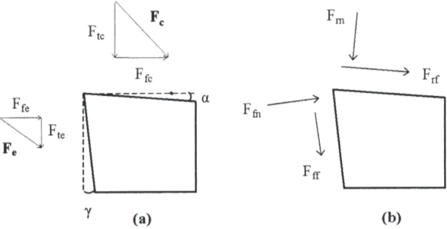
The process considered here is an or-thogonal cutting operation where the cutting edge is perpendicular to the cut-ting velocity, hence the process is two-dimensional with zero forces in the ra-dial direction. In the orthogonal cutting process, two fundamental cutting forces, the tangential force Ftand the feed force
Ff (Figs. 2 and 3) are considered. Each of these two cutting forces is resolved into two parts, the edge force Fe, which results from the contact between the flank face and the finished MDF sur-face, and the chip force Fc, which acts on the chip-tool rake face contact zone.
The edge force Feis further resolved into the two parts: tangential edge force
Fte, which is parallel to the cutting speed, and the feed edge force Ffe, which is perpendicular to the cutting speed. Similarly, the chip force Fc is also re-solved into the tangential chip force Ftc and feed chip force Ffc components (Fig. 3a). Considering a sharp edge, we
assume in this study that Feis applied at the edge as a line force, while Fcis ap-plied on the rake face. If the chip force is assumed to be proportional to the uncut chip area, and the edge force is related to the width of cut only, equations for the tangential and feed forces can be con-structed. Thus: Ft= Ftc+ Fte= Ktcbh + Kteb [1] Ff= Ffc+ Ffe= Kfcbh + Kfeb where: h = uncut chip thickness b = width of cut
Ktc, Kfcand Kte, Kfe = chip and
edge cutting coefficients, respectively For zero uncut chip thickness, h = 0, we assume that the chip forces Ftcand Ffc=
zero. Thus:
Fte= Ft and Ffe= Ff for (h = 0) [2] Experimentally, the tangential and feed forces are obtained from cutting tests with incremental feed rates. Since the edge force components Fteand Ffe are independent of the chip thickness h, and can be obtained from Ftand Ff ex-trapolated to h = 0, the chip force com-ponents Ftcand Ffccan be obtained by subtracting the edge forces from the measured forces Ftand Ffgiving:
Ftc= Ft Fte
Ffc= Ff Ffe
[3]
From Figure 3b, the normal and fric-tion force components, respectively Frn,
Ffn, on the rake face can be expressed as:
Frf= Ffccos + Ftcsin ,
Frn= Ftccos Ffcsin
[4]
We assume that the friction on the rake face satisfies a Coulomb friction model; therefore, the average friction coefficient on the rake face µrcan be evaluated using: r rf rn fc tc tc fc F F F F F F cos sin cos sin [5]
Thus, for a given uncut chip thickness
h, Equation [5] gives the average friction
coefficient on the rake face. Experimental results
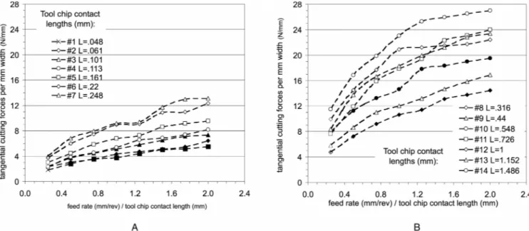
The 16 tools with different tool-chip contact lengths were tested for 8 incre-ments in chip thickness (feed rate) cov-ering a range up to 2 times the tool-chip contact length. For each test, the feed and tangential components of the cut-ting forces were measured. In order that the force data from a number of tests can be displayed on the same figure, the chip thickness (or feed rate) parameter was normalized with the tool-chip contact length of the respective test.
The 16 sets of data were divided into two groups and plotted in Figures 4a and 4b, which show the measured cut-ting forces per unit chip width in the tan-gential direction vs. the normalized chip thickness. The tangential force appears to increase fairly linearly, with the ex-ception of the ones having tool-chip contact length longer than 0.5 mm, with increasing normalized feed rate. The curves of the 16 tests also appear to be positioned fairly regularly in an ascend-ing order with the shortest tool-chip-contact-length curve occupying the low-est position (Fig. 4a) and the longlow-est tool-chip-contact-length curve occupy-ing the uppermost position (Fig. 4b).
The curves with tool-chip contact length longer than 0.5 mm appear to increase linearly at first until the normalized feed rate reaches around one, that is, the ac-tual feed rate equals the tool-chip con-tact length. Then the curves change abruptly, each to a new linear curve with a much lower rate of increase.
The corresponding feed forces (per unit chip width) were also plotted against the normalized feed rates and are
displayed in two groups (Figs. 5a and 5b). Contrary to the tangential forces shown in Figure 4, the positions of the feed-force curves with different tool-chip contact lengths appear to be at ran-dom. For tools with longer tool-chip contact length, a hint of decreasing feed force with increasing normalized feed rate exists. However, the pattern is highly irregular and does not follow any order of the tool-chip contact length
(Fig. 5b). On the other hand, for tools with shorter tool-chip contact lengths, the feed force appears at first to increase with the normalized feed rate until this ratio reaches about one. Then the feed force remains more or less constant with further increase in the normalized feed rate (Fig. 5a). The overall variation of the feed forces appears to cover a very narrow range from 2.5 N/mm to 5 N/ mm. Small variations in other test
pa-Figure 5. — Feed forces results. For each tool, the measured forces are shown in respect to the ratio feed rate/tool chip contact length. Feed forces are normalized in respect to cutting width. Figure 5a shows the results for tools 1 to 8. Figure 5b shows the re-sults for tools 9 to 14.
Figure 4. — Tangential forces results. For each tool, the measured forces are shown in respect to the ratio feed rate/tool chip con-tact length. Tangential forces are normalized in respect to cutting width. Figure 4a shows the results for tools 1 to 7. Figure 4b shows the results for tools 8 to 14.
rameters could have resulted in the ap-parent changes in the feed forces.
To clarify the results observed in Figures 4 and 5, a new set of tests was carried out for the tangential and feed forces versus tool-chip contact lengths with the feed rate kept constant in each test. Figures 6a and 6b show respec-tively the tangential force and the feed force vs. tool-chip contact length for three feed rates. The results clearly show that the tool-chip contact length has no effect on the tangential force. Rather, the tangential force increases with increas-ing feed rate. The feed forces shown in
Figure 6b appear to be independent of the tool-chip contact length and are within the range of 4 N/mm to 5 N/mm for the three feed rates tested. At the feed rate of 0.55 mm/rev, it appears that both the tangential force and the feed force increased with increasing tool-chip contact length for the very short lengths up to about 0.3 mm. It is postu-lated that for tools with a very short tool-chip contact length on the rake face, the chip formation and flow may be different than the general chip forma-tion process involving shear and defor-mation.
The tangential and feed forces (per unit chip width) shown in Figures 4 and 5 were further normalized by dividing each with the respective tool-chip con-tact length to obtain the corresponding specific cutting forces (per unit tool-chip contact area on the rake face). The specific tangential forces versus the nor-malized feed rates are shown in Figures 7a and 7b for the two groups of tools having the shorter and longer tool-chip contact lengths. The corresponding spe-cific feed forces are shown in Figures 8a and 8b. Interestingly, the specific tan-gential forces now decrease with increa-sing normalized feed rates and the effect
Figure 7. — Tangential specific forces results. For each tool, the specific forces are shown in respect to the ratio feed rate/tool-chip contact length. Figure 7a shows the results for tools 1 to 7. Figure 7b shows the results for tools 8 to 14. Figure 6. — Tangential (a) and feed (b) forces results for three feed rates and increasing tool-chip contact lengths.
of tool-chip contact length is reversed with the force curves appearing in a de-scending order for increasing tool-chip contact lengths. Of particular interest is the specific feed forces. They were transformed from a highly irregular pat-tern to an orderly display of the effects of normalized feed rate and tool-chip contact length. The specific feed force generally decreases with increasing nor-malized feed rate and also decreases
with increasing tool-chip contact length. In all cases, with both the specific tan-gential force and specific feed force, the effect of the normalized feed rate ap-pears to be pronounced until it reaches about one, that is when the actual feed rate equals the tool-chip contact length. For normalized feed rates higher than one, the specific cutting forces tend to-wards constant. In other words, the
ef-fect of the normalized feed rate diminishes to zero.
Distribution of
normal and friction forces
The measured cutting forces were ex-trapolated to obtain the feed and tangen-tial forces at zero chip thickness (zero feed rate), which provide a set of con-stant values for the edge force compo-nents described in the previous section (Eq. [2]). As already described in the earlier section, the cutting forces acting on the rake face were obtained by re-moving the edge forces from the mea-sured cutting forces (Eq. [3]). The feed and tangential components of the chip force on the rake face were further re-solved to obtain the normal and friction forces on the rake face according to Equation [4]. The rake face forces mea-sured in experiments where the normal-ized feed rate of one, that is, feed rate equals the tool-chip contact length, are plotted in Figure 9 for each tool. One of the reasons for choosing these force val-ues is that in the following calculations the chip load is assumed to distribute over the tool-chip contact area exactly, that is when the chip thickness (or feed rate) equals the tool-chip contact length.
Frnand Frfare normalized forces with respect to the width of cut (b = 4mm). It can be observed from Figure 9 that the normal force-uncut chip thickness (equivalent to the feed rate) relationship
Figure 9. — Friction and normal forces Frnand Frf. Frnand Frfare resulting from the
projection of the chip force along the rake face in parallel and orthogonal direction. Only values where the feed rate is equal to the tool-chip contact length have been considered.
Figure 8. — Feed specific forces results. For each tool, the specific forces are shown in respect to the ratio feed rate/tool-chip con-tact length. Figure 8a shows the results for tools 1 to 7. Figure 8b shows the results for tools 8 to 14.
is logarithmic, whereas the friction force-uncut chip thickness is almost constant. The following empirical rela-tionships were obtained by applying a least squares curve fit to the measured rake face forces:
Frn(h) =
0.99 + 7.39h + 3.937 ln(h + 0.05) [6]
Frf (h) = 1.634 + 0.325 h
Using Equation [5] and the calculated normal and friction forces, the corre-sponding friction coefficients were
ob-tained and displayed in Figure 10. Again, applying a least square curve to fit the data, an equation is obtained for the average friction coefficient on the rake faceµrin terms of the uncut chip thickness h.
r= 0.149.h− 0.508 [7]
The results in Figure 10 show that the coefficient of friction decreases rapidly with uncut chip thickness in the low chip thickness region, i.e., near the tool edge, and just as rapidly attains a near-con-stant value as the chip thickness is
fur-ther increased to about 0.4 mm and be-yond. In metal cutting, the presence of a sticking region near the tool edge is now well known (Moore 1975), which con-tributes to a sharp increase in friction coefficient. In a separate friction experi-ment using the flat face of a piece of car-bide tool material pressed and slid against MDF at a constant sliding speed, it was observed that initially the friction coefficient decreases rapidly with in-creasing applied normal load to around 0.1 (Styles 2002). The coefficient of friction became more or less constant and remained at about 0.1 as the applied normal force was increased to more than 100 N. Similar friction coefficient val-ues around 0.12 have also been reported by others (Niedzielski et al. 2000).
Beyond the sticking region, the chip starts to slide over the rake face with a lower friction coefficient. Although fric-tion in MDF machining is not well known, it seems that the chip cracks close to the cutting edge, and is com-pressed and trapped with limited motion close to the edge. It is then pushed out into the free zone on the rake face much like a dust without having a solid body energy. This may explain the low tion coefficient values, or the low fric-tion forces.
Since the normal and friction forces shown in Figure 9 have the units N/mm chip width, further dividing these forces by the tool-chip contact length h yields the average stresses, σaverage and
τaverage, respectively, on the rake face.
These stresses versus the uncut chip thickness (feed rate) are plotted in Fig-ure 11. The curves in FigFig-ure 11 show that the average stresses are very high for short tool-chip contact lengths and they decrease rapidly as the tool-chip contact length is increased to about 0.4 mm. At further increases from 0.4 mm to 1.5 mm, the stresses level off and at-tain very low values. For a first ap-proach, it is therefore safe to assume that the tool-chip contact lengths could be substituted for the distances x from the tool edge to obtain the stress distribution along the tool rake face near the edge. Thus, the stress curves in Figure 11 rep-resent the average stress-distributions on the rake face. In later approaches, this stress model can be refined by reducing the influence of total contact lengths in the data. These estimated stress curves are represented by the following equa-tions:
Figure 11. — Normal and shear stress in respect to the position on rake face; values are obtained by dividing normal and friction forces by the tool-chip contact area. Figure 10. — Friction coefficient as a function of the feed rate; the friction coefficient is obtained by dividing Frfby Frn.
average= 12.504 · x−0.444
average= 1.86 · x−0.952
[8]
where:
x = the contact position on the
rake face from the cutting edge
σaverage,τaverage = the average normal and shear stresses acting on the rake face, respectively (MPa)
Dividing the expression for τaverage by
the expression for σaverage of Eq. [8]
would yield the same logarithmic ex-pression for the coefficient of friction shown in Figure 10.
The distribution of normal and fric-tion stress on the tool along the chip con-tact zone indicates that the cutting edge is loaded most within 0.1mm, and al-most diminishes after 0.25 mm when machining MDF. One can make a rec-ommendation to tool manufacturers that the cutting wedge must be strongest within the first 0.25 mm of the rake, and the rake face can be ground with a sec-ondary rake angle. The latter would lead to a reduction in friction force with the potential of reducing wear on the tool. The tool edge geometry can be opti-mally designed to resist the stresses on the tool by the pressure and friction dis-tribution given above.
Conclusion
Unlike in metal cutting, where the process is dominated by plastic shear, machining MDF and wood is dominated by fracture and compression of MDF dust between the incoming material and the rake face of the tool.
This paper presents an approach to evaluate the friction and normal load distribution on the rake face of the tool for cutting MDF. The cutting forces are resolved into rake and flank components first. By limiting the rake face-chip con-tact lengths via restricted rake concon-tact, the distributions of friction and normal stresses on the rake face are estimated. The results indicate that both friction and normal loading of the rake face de-creases significantly within the first 0.25 mm of the contact. The information can be used to help estimate the stress
distribution on the tool face and hence better and optimal tool design. The re-sults also point to the importance of hard coatings for wear protection applied to within the first 0.25 mm on the rake face, which can be then ground with a secondary rake angle to further mini-mize the friction between the restricted rake face contact and the chip. The de-sign of the microbevel (Decès-Petit et al. 1999) on the tool edge can also be opti-mized using the information. Finally, heat generated by the chip can be also estimated by the stress distributions on the rake face.
Notations
h = uncut chip thickness
(mm)
d = width of cut (mm) Ft, Ff = tangential force, feed
force (N)
Fc, Fe = chip force, edge
force (N)
Ftc, Ffc = tangential and feed
component of the chip force (N)
Fte , Ffe = tangential and feed
component of the edge force (N)
Frn , Frf = normal and friction
forces applied on the rake face (N)
Kte, Kfe = edge cutting force
coefficients (in tangential and feed direction) (N/mm)
Ktc, Kfc = chip cutting force
coefficients (in tangential and feed direction) (N/mm2
) µr = average friction
coefficient of tool-chip contact on the rake face
i = tool number
Li = rake face length of the
tool i (mm)
Literature cited
Altintas, Y. 2000. Manufacturing Automation: Metal Cutting Mechanics, Machine Tool Vi-brations, and CNC Design. Cambridge Univ. Press, New York. ISBN 0521650291.
Decès-Petit, C., P. Ko, and B. Cvitkovic. 1999. Influence of back microbevel on orthogonal wood cutting. In: Proc. 14th Inter. Wood Ma-chining Seminar. where could a reader
ob-tain this? pp. 397-405.
Dippon, J., H. Ren, F. Ben Amara, and Y. Altintas. 2000. Orthogonal cutting mechanics of medium density fiberboards. Forest Prod. J. 50(7/8):25-30.
Engin, S., Y. Altintas, and F. Ben Amara. 2000. Mechanics of routing medium density fiberboard. Forest Prod. J. 50(9):65-69. Franz, N.C. 1958. Analysis of the Wood
Cut-ting Process. Engineering Research Inst., Univ. of Michigan Press, Ann Arbor, MI. Holmberg, S. 1998. A numerical and
experi-mental study of initial defibration of wood. Rept. TVSM 1010. Lund Univ., Lund Insti-tute of Tech., Sweden. 203 pp.
Kivimaa, E. 1950. Cutting force in wood-work-ing. PhD thesis. Finland State Inst. for Tech. Research, insert city, Finland.
McKenzie, W.M. 1960. Fundamental aspects of the wood cutting process. Forest Prod. J. 10(9):447-456.
__________, P. Ko, R. Cvitkovic, and T. Ringler. 1999. Towards a model predicting cutting forces and surface quality in routing layered boards. In: Proc. 14th Inter. Wood Machining Seminar. where could a reader obtain this? Moore, D.F. 1975. Principles and Applications
of Tribology. Pergamon Press Ltd., Oxford, UK. pp. 250-254.
Niedzielski, P., S. Miklaszewski, P. Beer, and A. Sokolowska. 2000. Tribological properties of NCD coated cemented carbides in contact with wood. Diamond and Related Materials (10):1-6.
Stewart, H.A. 1991. A comparison of tool mate-rials, coatings, and treatments related to tool wear during wood machining. Forest Prod. J. 41(9):61-64.
__________. 1989. Analysis of tool forces and edge recession after cutting medium density fibreboard. In: Proc. 9th Inter. Wood Ma-chining Seminar. pp. 320-341. where could a
reader obtain this?
Styles, E. 2002. Sliding friction tests of carbide tools on MDF. Tech. Rept. The National Re-search Council of Canada, Innovation Centre, Vancouver, BC, Canada.
Suzuki, S., J. Kobayashi, T. Tochigi, and H. Fukui. 1997. Machinability of medium den-sity fiberboard. I. The effects of clearance an-gle and depth of cut on the machinability in end surface cutting. Mokuzai Gakkaishi 43(9):731-737.
9485 P & P: This study presents a method to estimate the cutting forces distributions on the tool tip, which can be used to improve the tool geometry design, and provide a better understand-ing of the hard coatunderstand-ing failure around the tool tip.