HAL Id: hal-01759337
https://hal.archives-ouvertes.fr/hal-01759337
Submitted on 24 Jun 2019
HAL is a multi-disciplinary open access
archive for the deposit and dissemination of
sci-L’archive ouverte pluridisciplinaire HAL, est
destinée au dépôt et à la diffusion de documents
Design of a Wooden Five-bar Mechanism
Lila Kaci, Sébastien Briot, Clément Boudaud, Philippe Martinet
To cite this version:
Lila Kaci, Sébastien Briot, Clément Boudaud, Philippe Martinet. Design of a Wooden Five-bar
Mechanism. 22nd CISM IFToMM Symposium on Robot Design, Dynamics and Control (RoManSy
2018), Jun 2018, Rennes, France. �hal-01759337�
Design of a Wooden Five-bar Mechanism
Lila Kaci*, S´ebastien Briot*and Cl´ement Boudaud†and Philippe Martinet‡*Laboratoire des Sciences du Num´erique de Nantes (LS2N),
UMR CNRS 6004, ´Ecole Centrale Nantes, France
†LIMBHA, Goupe ´Ecole Sup´erieure du Bois, Nantes, France ‡Centre de Recherche INRIA Sophia Antipolis, Nice, France
Abstract
Eco-design of robots is a field of research which has been rarely ex-plored in the past. In order to considerably decrease the environmental im-pact of robot during the design phase, metal or carbon composite parts can be replaced by bio-sourced materials, such as wood. Indeed, wood has in-teresting mechanical properties, but its performance / dimensions will vary with the atmospheric conditions / external solicitations and with the con-ditions in which trees have grown. This paper deals with the design of a stiff and accurate wooden five-bar mechanism. First, a control-based de-sign problem is formulated. This problem aims at finding the optimal pa-rameters of the robot, taking into account the nature of the desired control (sensor-based control). Then, reliable topology optimization methodology is proposed, taking into account the variability of the wood performance and that will allow the definition of robot architectures (shape of the links) for which the impact of this variability in terms of deformation is minimal. Fi-nally, the optimal design variables are given and are used for the realisation of industrial prototype of a wooden five-bar mechanism.
1
Introduction
The Climate Change Mitigation (CCM) has become a priority in the world, as shown during the COP21. It becomes urgent to decrease the Environmental Im-pact (EI) of the human activities. Robotics, which takes an increasing place in our everyday life, must also be part of this effort. A recent study (Fiz) shows that, contrary to what could be imagined, a large percentage (around 50 %) of the EI during the entire robot life is due to the use of metallic materials (steel or alu-minum, even if they are recycled) for the design of their links. The percentage is even worth if carbon composites are used. The rest of the EI is globally due to the robot energy consumption during use. A method to reduce EI of robot design, is to replace the polluting metals and carbon composites with bio-sourced materi-als (BSM) that have a little (even no) EI (Thakur (2013)). Moreover, BSM have
good stiffness performance, and their quantity is only limited by their growing time (Kretschmann (2010)). In this work, developped in the scope of the French project RobEcolo (Rob), we are interested in using wood instead of metals to de-sign the robot links.
Using wood in machines is not a new idea. For instance, it is used in chassis of cars (Mor). It found also applications in the design of buildings due to its stiffness and low cost (Kretschmann (2010)). It is also used in Robotics for the design of mock-ups and proof-of-concept prototypes (Quigley et al. (2011)). However, a detailed study of these works shows that wood is never used in critical parts ensuring accuracy. Indeed, the wood performance / dimensions will vary with the atmospheric conditions / external solicitations and with the conditions they have grown (Kretschmann (2010)); thus, new robot design issues appear: How to be sure that an industrial robot made with wood can be accurate and stiff even if wood properties vary? A first attempt to introduce wood in industrial robot design was presented in Laurent et al. (2010). The results showed that the approach was valid enough to compete with usual materials. However, this study did not deal with the aforementioned issues.
In this paper we introduce a design methodology leading to the manufacture of a stiff and accurate wooden five-bar mechanism. This methodology is based on two optimization problems that can be solved in cascade. First, control-based design approach is used. This approach allows to take into account the specificities of the controller used to servo the robot motions, and aims at finding the length of the links of the five-bar mechanism. Then the shape of the robot links using the reliable topology optimisation is developed. This problem is subject to a set of constraints related to the elastostatic and dynamic performance of the robot. Finally, the optimal length and shape of the wooden five-bar mechanism links are given and are used for the development of an prototype.
2
Design Process
The planar five-bar mechanism is shown in Fig. 1a. It is a two degrees-of-freedom (dof ) parallel robot able to achieve two translations in the plane (x0Oy0). The
end-effector is located at point C. The mechanism, is composed of five revolute joints, two of them located at point A1and A2 are active while the others are passive.
The links at points Ai and Bi (i = 1,2) are called the proximal links and between
points Biand C the distal links. In this work, our objective is to design a wooden
five-bar mechanism, the specifications that the robot should satisfy are summed up in Tab. 1. The robot should be as compact as possible due to some industrial constraints. Moreover, in order to ensure the accuracy of the robot even of the dimensions of the wooden links may vary with the atmospheric conditions, sensor-based controllers will be used. The most common approach consist of the direct
(a) Five-bar mechanism (b) Largest regular dexterous workspace of the optimizes five-bar mechanism
Figure 1: Five-bar mechanism and the optimized one
Table 1: Specifications for the Wooden Five-bar Mechanism
Absolute Positioning accuracy emax 0.5 mm
Regular workspace size 800 mm × 200 mm Deformations under forces f1= [50 N 0 N 1 Nm]T 0.5 mm
and f2= [0 N 50 N 1 Nm]T 0.25 mrad
observation of the end-effector pose. In some cases however it may be difficult or unwise to observe the end-effector of the robot, e.g. in the case of a five-bar mechanism the end-effector is a point. For this reason we decided to define a controller based on the observation of the distal links, as in Andreff et al. (2007). However, as shown in Briot et al. (2015) this controller is not free of singularities, that effect its accuracy performance which that not only depend on the camera localisation and specifications but also on the robot dimensions as shown in Kaci et al. (2016). Thus the optimization process must take all this parameters into account.
2.1 Link Length Optimization
The first design optimization problem aims at finding the optimal lengths of the robot links that minimize the footprint size of the five-bar mechanism in the plane of motion for a prescribed regular dexterous workspace, taking into account the controller accuracy performance. Four cameras with 1920 × 1200 pixels resolution are supposed to observe the two links attached to end-effector to control the robot end-effector pose. We introduced in Kaci et al. (2016) a procedure to define the error model between a single camera and the end-effector and these to define the robot optimal design variables. This method is adapted to the case of four cameras to optimally design a five-bar mechanism. Based on Kaci et al. (2016), we solved
Table 2: Optimal Design Solution of the Wooden Five-bar Mechanism
A[m2] l0[m] l1[m] l2[m]
0.1372 0.125 0.280 0.400
Table 3: Optimal Position and Orientation of Cameras
Pos/Ori xc[m] yc[m] zc[m] φ [rad] θ [rad] ψ [rad] Camera3 0.01 0.2291 0.75 0 π 0 Camera4 0.02 0.100 0.100 0 π 0
the following optimization problem: minimize A= LH
over x
subject to `Wx> `Wx0 and `Wy> `Wy0
(1)
Where: x = [`0`1`2xc1xc2xc3xc4] with `0= `A1A2, `1= `A1B1 = `A2B2 and `2=
`B1C= `B2C, and xci(i = 1 to 4 ) is a vector of dimension 6 defining the position and
orientation of the cameras. A = LH is the robot footprint (Figure 1a). `Wx and `Wy
are the dimensions along x0and y0of the rectangular dexterous workspace Merlet
(2006). The robot must have a rectangular dexterous workspace of rectangular shape with dimensions along x0bigger than `Wx0= 800 mm and along y0of `Wy0=
200 mm in which the following properties are certified: • no Type 2 singularities of the robot,
• the end-effector is within the image frame and thus the legs can be observed, • knowing the resolution of the camera, the resolution of the end-effector
po-sition should be lower than 0.5 mm.
• the static forces exerted into the passive joints are proportional to 1/ sin ξ , ξ being the angle between the distal links (Briot et al. (2013)). Consequently, it is decided that sin ξ should be higher than 0.1 to avoid excessive efforts in the joints.
The optimal design variables of problem (1) are given in Tab. 2 and Tab. 3. The architecture of the optimized five-bar mechanism and the position of the dexterous regular workspace is illustrated in Fig. 1b. It should be mentioned that, in order to reduce the number of decision variables in the optimization problem, only the po-sition/orientation of cameras 3 and 4 are optimized. Then, the popo-sition/orientation of the two other cameras is obtained by symmetry with respect to the y0axis.
2.2 Link Topology Optimization
As mentioned in Tab. 1, the deformation of the wooden five-bar mechanism should be lower then 0.5 mm under external forces. To reach the desired stiffness
of the robot, topology optimization of the robot proximal links is used. Moreover, in order to decrease the dimensional variability of wood due to humidity, we de-cided to design our links with a novel type of wood named acetylated beech (Hill (2006)). This wood is known to have many advantages over raw wood species in terms of durability and dimensional stability. However, this acetylated beech, as any other type of wood, presents a normal distribution of its Young’s modulus: here, the mean value is equal to 1277.2 MPa and the standard deviation is equal to 2043.5 MPa. To deal with this variation of the mechanical properties of acetylated beech, reliable topology optimization is developed. It should be mentioned that in what follows, only the shape of the robot proximal link are optimized. Indeed, the controller (Andreff et al. (2007)) impose that the distal links are cylindrical, for reason of facility of observation.
Modeling of the linkages elastic behavior Topology optimization uses the same physical model as in the FEM for modelling of a link, except that an interpolation scheme is used in order to define an artificial material. This method is called the Solid Isotropic Material with Penalization (SIMP, Bendsoe and Sigmund (1999)) and is known to be the most effective and the most widely used material inter-polation scheme. This interinter-polation scheme is adopted in order to avoid having optimization results with too much intermediate material density, i.e. in order to have a final design solution with densities only equal to ρi j= 1 (which represent
the presence of materials)or ρi j= 0 (which represent the absence of materials)
without too many intermediate values (0 < ρi j< 1) that are difficult to manage
by the designer. The SIMP scheme is used to parameterize the Young’s modu-lus associated with the stiffness matrix of the finite element i j and it is defined as follows:
Ei j= Emin+ ρi jp(E0− Emin), with ρi j∈ [0, 1] (2)
where E0is the Young’s modulus of the material, Emin is a very small stiffness
value assigned to void regions in order to prevent the stiffness matrix from becom-ing sbecom-ingular, p (typically p = 3) is the penalization factor, and Ei jis the Young’s
modulus of element j of the body i corresponding to the density variable ρi j. Then,
based on this definition of the Young’s modulus for the element i j, we build its stiffness matrix. Finally, once all elementary matrices are defined, the computa-tion of the body and linkage stiffness matrices is the same as in the tradicomputa-tional methodology (Shabana (2005)). Once the linkage stiffness is obtained, the elastic performance of the mechanism can be defined, in our case we will consider the deformation of the five-bar mechanism end-effector. For dealing with reliability of the robot performance due to the uncertainty of the wood mechanical properties, reliable topology optimisation approach must be used. We take advantages of the work Asadpoure et al. (2011) to define the following constraint included in the
design process:
E(kuek) + kσ (kuek) ≤ umax (3)
Where: E(.) is the expectation operator, σ (.) is the standard deviation operator, k is a positive real and ueis the deformation vector at the node located at the center
of the end-effector under a giving loading and umaxis the maximum desired
defor-mation. This constraint, is derivated from the well-known Bienaym´e-Tchebichev theorem, which states that the probability, for a stochastic variable X , to have | X − E(X) | ≥ k, is lower than σ (X )2
k2 . Thus, by increasing the value of k in (3) we
reduce the probability to have a robot whose deformation under the loading given in Tab. 1 will be bigger than 0.5 mm. For instance, with k = 3, the probability to have a robot whose deformations are acceptable is almost 90 %. Approximate for-mulas are provided in Asadpoure et al. (2011) to compute E(kuek) and σ (kuek)
and their derivatives, which are necessary in topology optimization process.
Optimization Problem The topology optimisation problem can be formalized as:
min
ρ F= τ 2(T∗)
under g1i= (δC2(fi, q∗) − δmax2 )/δmax2 ≤ 0, i = 1, 2
g2i= (θC2(fi, q∗) − θmax2 )/θmax2 ≤ 0, i = 1, 2
(4)
Where q∗are the selected exciting configurations for the computation of the trans-lational/rotational deformation when the loading fi is applied (i=1,2).
Configu-ration q∗can be found using the methodology proposed in Briot and Goldsztejn (2017). The objective is to minimize the RMS of the actuators torques τ along optimized trajectoryT∗selected based on the approach shown in Briot and Gold-sztejn (2017). Concerning the constraints, we must ensure that wherever in the dexterous workspace defined in section 2.1, the elastic translational displace-ment δC of the end-effector under external forces f1= [50 N 0 N 1 Nm]T and
f2= [0 N 50 N 1 Nm]T is lower than δmax = 0.5 mm and that the rotational
dis-placement θCof the distal links at the end-effector is lower than θmax= 0.25 mrad.
Here, δC = E(kudek) + kσ (kudek) and θC= E(kurek) + kσ (kurek), with ude is
the transitional deformation of the node at the end-effector and ureis the rotational
one. Indeed, we recall that in our case k = 3 in order to have a design reliability of 90 %.
Result of the topology optimization The initial design domain for the proximal links is represented in Fig. 2a. Each link has two empty holes at the extremely for the joints insertion (motor shaft at points Ai, and passive rotary joints for all
others. For the meshing of the links, 24132 planar elements of size 1 × 1 mm are used and with 50 mm of thickness. The obtained shape of proximal links is shown
(a) Design of the proximal links: initial design domain
80 mm
280 mm
(b) Design of the proximal links: final design for k=3
Figure 2: Evolution of the design of the five-bar links: the links are shown in gray-scale (black elements correspond to ρi= 1, white elements to ρi= 0, and gray
elements to 0 < ρi< 1)
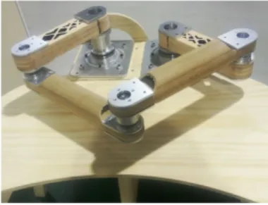
Figure 3: Final prototype of a wooden five-bar mechanism.
in Figure 2b. All models and optimisation algorithms have been encoded with Matlab in the Windows 7 environment. The computation time took around 4948 sec (for a Pentium 4 2.70 GHz, 16 GB of RAM).
Based on the previous optimisation results, a prototype of a wooden five-bar mechanism was designed (Fig. 3). Our future works will concern its visual servo-ing and the experimental validations of the obtained theoretical results.
3
Conclusion
Robot eco-design is a field of research in Robotics that should be deeper investi-gated: this could contribute to the Climate Change Mitigation. In order to con-siderably decrease the environmental impact of robot during the design phase, we proposed to replace metal or carbon composite parts by bio-sourced materials, such as wood. Wood has interesting mechanical properties but also drawbacks: its mechanical performance encounters a large variability. In order to be able to design a stiff industrial robot, robust design approaches must be used. In this pa-per, we developed a wooden parallel robot, two optimization problems have been formulated and solved in cascade in order to find the robot optimal design archi-tecture for which the impact of the wood properties variability is minimal. Finally, the CAD design and prototyping of the wooden five-bar mechanism and its key
technological solutions have been described.
Our future works, will concern the implementation of sensor-based controllers. Then the experimental validations of the theoretical results obtained in the frame-work of the RobEcolo project will be made soon to characterize the robot proper-ties.
Acknowledgement
This work was supported by the project RobEcolo funded by the French R´egion Pays de la Loire (Convention No. 2015-10773).
Bibliography
Fizians report. URL http://pagesperso.ls2n.fr/~briot-s/Project_Review.html. Car manufacturer Morgan. URL http://www.morgan3wheeler.co.uk/$\sharp$technology. Project RobEcolo. URL http://robecolo.irccyn.ec-nantes.fr/.
N. Andreff, T. Dallej, and P. Martinet. Image-based visual servoing of gough-stewart parallel manipu-lators using legs observation. IJRR, 26(7):677–687, 2007.
A. Asadpoure, M. Tootkaboni, and J.K. Guest. Robusttopology optimization of structures with uncer-tainties in stiffness application to truss structures. Computers and Structures, 2011.
M.P. Bendsoe and O. Sigmund. Material interpolation schemes in topology optimization. Archive of Applied Mechanics, 69, 1999.
S. Briot and A. Goldsztejn. Global topology optimization of industrial robots with the linearization method. 2017.
S. Briot, V. Glazunov, and V. Arakelian. Investigation on the effort transmission in planar parallel manipulators. ASME JMR, 5(1), 2013.
S. Briot, P. Martinet, and V. Rosenzveig. The hidden robot: an efficient concept contributing to the analysis of the controllability of parallel robots in advanced visual servoing techniques. IEEE Transactions on Robotics, 31(6):1337–1352, 2015.
C.A.S. Hill. Wood Modification: Chemical, Thermal and Other Processes. John Wiley & Sons, Ltd, 2006.
L. Kaci, S. Briot, C. Boudaud, and P. Martinet. Control-based design of a five-bar mechanism. In Proceedings of EuCoMeS, Nantes, France, 2016.
D.E. Kretschmann. Ch. 5: Mechanical properties of Wood. Forest Products Laboratory, United States Department of Agriculture Forest Service, Madison, Wisconsin, 2010.
T. Laurent, J.L. Kergueme, O. Arnould, and D. Dureisseix. Vers un robot en bois: Premi`ere partie. 168, 2010. In French.
J.P. Merlet. Parallel Robots. Springer, 2nd edition, 2006.
M. Quigley, A. Asbeck, and A. Ng. A low-cost compliant 7-DOF robotic manipulator. In Proceedings of the 2011 IEEE International Conference on Robotics and Automation (ICRA 2011), may 2011. A. Shabana. Dynamics of Multibody Systems. Cambridge University Press, 2005.

![Table 2: Optimal Design Solution of the Wooden Five-bar Mechanism A [m 2 ] l 0 [m] l 1 [m] l 2 [m]](https://thumb-eu.123doks.com/thumbv2/123doknet/12271175.321643/5.892.250.694.315.371/table-optimal-design-solution-wooden-bar-mechanism-m.webp)