HAL Id: hal-00994418
https://hal.inria.fr/hal-00994418
Submitted on 21 May 2014
HAL is a multi-disciplinary open access
archive for the deposit and dissemination of
sci-entific research documents, whether they are
pub-lished or not. The documents may come from
teaching and research institutions in France or
abroad, or from public or private research centers.
L’archive ouverte pluridisciplinaire HAL, est
destinée au dépôt et à la diffusion de documents
scientifiques de niveau recherche, publiés ou non,
émanant des établissements d’enseignement et de
recherche français ou étrangers, des laboratoires
publics ou privés.
Epitome inpainting with in-loop residue coding for
image compression
Safa Chérigui, Martin Alain, Christine Guillemot, Dominique Thoreau,
Philippe Guillotel
To cite this version:
Safa Chérigui, Martin Alain, Christine Guillemot, Dominique Thoreau, Philippe Guillotel. Epitome
inpainting with in-loop residue coding for image compression. ICIP - IEEE International Conference
on Image Processing 2014, Oct 2014, Paris, France. �hal-00994418�
EPITOME INPAINTING WITH IN-LOOP RESIDUE CODING FOR IMAGE COMPRESSION
Safa Ch´erigui
1,2, Martin Alain
1,2, Christine Guillemot
1, Dominique Thoreau
2and Philippe Guillotel
21INRIA 2Technicolor Research and Innovation
Campus de Beaulieu, 35042 Rennes Cedex France Av. des Champs Blancs, 35576 Cesson-S´evign´e France
[email protected] [email protected]
ABSTRACT
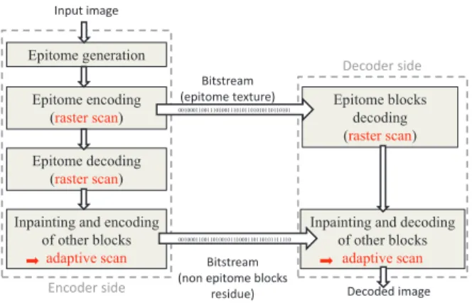
This paper describes a novel image coding scheme based on epit-ome inpainting. An epitepit-ome containing a factorized texture rep-resentation of the image is first coded and transmitted. The de-coded epitome is then inpainted by propagating its structure and texture with extended H.264 Intra directional prediction modes and advanced neighbor embedding methods. The blocks to be inpainted are processed according to an adaptive scanning order which adapts to the image content and gives a higher priority to the blocks having strong structures. The inpainting step has been incorporated in the coding loop of an H.264 encoder, leading to a bitrate saving of up to 48.12% with respect to H.264 intra.
Index Terms: Intra coding, epitome, inpainting, H.264. 1. INTRODUCTION
The concept of epitome was first introduced in [1] by Jojic et al. as a condensed representation of the image texture. Different types of epitomes have then been proposed in the literature. While the epit-ome in [1] is obtained using a patch-based probability model learned from the input image, the authors in [2] construct instead the epitome with self-similar or repeatable texture patterns found using the KLT algorithm [3][4]. The epitome is in this case the union of epitome charts which are pieces of repeatable textures found in the image. The epitome is associated with a transform map that links patches in the epitome to original patches in the input image. The epitome con-struction has been improved in [5] by using a bi-directional similar-ity measure based on the notion of “completeness” and “coherence”. In this paper we propose a novel image coding technique based on epitome inpainting. Note that the use of epitomes has already been considered in the literature for image coding. The authors in [2] encode the epitome and its associated transform map, which are then used by the receiver to reconstruct the image. The use of the epitome of [1] is also considered in [6],[7] together with template matching for Intra prediction. In [8], the epitome constructed with a simple block matching, together with the associated map, is used to generate a reference image in the same vein as in H.264 temporal prediction.
The coding scheme described here significantly differs from pre-vious approaches, since it relies on the inpainting of the epitome with in-loop residue coding. The approach implies a significant change with respect to classical coding architectures, since the image blocks are not processed any more in a raster scan order but instead accord-ing to an adaptive order which depends on the local image struc-ture. The local image structure is taken into account in a priority term which allows deciding which block of size8 × 8 should be inpainted first. A new scanning order of all the other blocks in the macro-block has then been defined depending on the position of the
first inpainted block based on the priority term. The adaptive scan-ning order is needed to take into account the ”arbitrary” shape of the local neighborhood of the block to be inpainted. It also aims at giv-ing a higher priority to blocks for which the local neighborhood has stronger structures.
In a nutshell, an epitome is first constructed using the method de-scribed in [8]. This epitome is coded with the scheme introduced in [8] and transmitted. The epitome texture and structure is block-per-block propagated using a set of possible and rate-distortion compet-ing modes which include extended H.264 Intra directional predic-tion modes as well as a Locally Linear Embedding (LLE) technique [9] and the optimized Map-Aided Locally Linear Embedding [10]. Once a block has been predicted, its residue is computed coded and added to the predictor to reconstruct the current block before contin-uing the inpainting process. Note that here the transform map is not used. Experimental results show a significant PSNR-rate gain (up to 48.12% using the Bjontegaard measure).
The rest of this paper is organized as follows. Section 2 reviews the related work on intra image coding and epitome construction. Section 3 describes the proposed coding scheme based on epitomes with in-loop residue coding. The experimental results are discussed in section 4.
2. BACKGROUND 2.1. Intra image coding
The H.264/AVC standard defines three types of intra prediction modes depending on the block size: the Intra-4x4, Intra-8x8 and Intra-16x16 [11]. For Intra prediction of 16x16 blocks, four intra prediction modes can be used while for Intra prediction of 4x4 and 8x8 blocks, nine modes have been defined. In addition to the so-called “DC” mode which consists in predicting the entire block from the mean of neighboring pixels, eight directional prediction modes have been specified. The prediction is done by simply propagating (or interpolating) the neighboring pixel values along the specified direction. The best mode is then selected using a rate distortion op-timization (RDO).
The improvement of these Intra prediction modes has received a lot of attention in the past years. For example, the authors in [12] consider bi-directional intra prediction (BIP) which combines two existing prediction modes. To be able to do so an alternative cod-ing order was proposed within a macroblock, but macroblock are still raster scanned. An adaptive scanning order for blocks and MB was introduced in [13] in order to maximizes the number of rerence pixels available for intra prediction. The intra coding ef-ficiency has also been improved by transposing temporal predic-tion methods, using block-matching (BM) [14] or template match-ing (TM) [15], to Intra prediction. An alternative spatial prediction
algorithm based on TM has been described in [16]. A template is formed by previously encoded pixels in the close neighborhood of the block to be predicted. The best match between the template of the block to be predicted and candidate texture patches with the same shape, within a causal search window, gives the predictor for the cur-rent block to be coded. This approach has later been improved in [17] by averaging multiple TM predictors. Further PSNR-rate gains have been achieved by considering linear combinations of multiple patches (predictors) using for example the locally linear embedding (LLE) and optimized Map aided locally linear embedding (oMA-LLE) methods [9][10].
2.2. Epitome construction
The epitome construction method which we use here is the one de-scribed in [8] and which we briefly recall here. Note that one could also consider the method of [2] using the KLT algorithm instead of a simple BM algorithm to find the repeatable pieces of texture. But this second method has to retain in the transform map φ all the in-formation about translations, rotation angles, scaling factors and re-flections, which can make it really heavy and CPU time consuming. In these approaches, the image is described by its epitome E and a transform (or correspondence) map φ. The epitome E is composed of disjoint pieces of texture called epitome charts. Each epitome chart corresponds to a specific region in the image. The set of all the epitome charts constitutes the epitome E.
The algorithm in [8] proceeds by first searching for self-similarities within the image. For each non-overlapping block in the input image, the method searches for the set of patches in the image with similar content. That is, for each block Bi ∈ I, a list of best
matching patches (which may overlap) is constructed. Once all the lists have been created for all the image blocks, a dual list of the best matching blocks to a given patch M(i, j) is also constructed.
The first epitome chart is then initialized by the texture patch which allows reconstructing the image with the highest fidelity. All the image blocks having this patch as one of the best matching patches in the list are replaced by this matching patch. The mean square reconstruction error is computed by setting the pixels which are not reconstructed to zero. In others words, the initialization of an epitome chart consists in searching in all the lists, the texture patch so far not used at the previous iterations that allows the minimization of the reconstruction error (the MSE).
Once initialized, the epitome chart has to be progressively grown in a way which optimizes the trade-off between the MSE of the re-constructed image and the number of pixels (as a rough measure of rate cost) in the epitome. The set of matched patches which overlap the current epitome chart is identified. For each possible candidate, the image blocks which can be reconstructed by the enlarged area of the epitome chart are determined from the corresponding list. The candidate minimizing a rate-distortion cost (that is decreasing the most the MSE under the constrained of a limited number of addi-tional pixels in the epitome chart) is selected. The current chart keeps on growing until there are no more matched patches overlapping the current chart which can represent other blocks. When the current chart cannot be extended anymore and when the whole image is not yet full represented by the current epitome, another epitome chart is initialized at a new location in the image. The process ends when the whole image is reconstructed by the epitome.
Note that the epitome charts are padded in order to be aligned with the block structure (here with the8 × 8 block grid) of the codec used.
2.3. Image coding based on epitome
As mentioned in the introduction, epitomes have already been con-sidered for image coding, the epitome being simply used as extra reference texture for classical TM-based Intra prediction [6], or for generating a reference image which is then used for H.264 inter-frame prediction [8]. In [2], the epitome is used only (i.e. with-out transmitting a prediction residue) with the correspondence map to reconstruct the image on the receiver side. The PSNR-rate per-formance of this scheme, with no residue coding, is however lim-ited, as shown in[8]. The goal was here to push further the idea of epitome-based image coding, but considering a completely different approach (using inpainting with in-loop residue coding) which does not require the transmission of the correspondence map. This new approach implies a radical change in the coding architecture.
3. EPITOME INPAINTING WITH IN-LOOP RESIDUE CODING
The main steps of the coding scheme are depicted in Fig. 1. The epitome is generated using the method described in section 2.2 and encoded in a raster scan order using the image coding algorithm described in [10] which is based on an H.264 Intra coder plus ex-tra Inex-tra prediction modes have been added, using block matching within the same frame, as well as locally linear embedding (LLE) based methods. The LLE based methods can be regarded as exten-sions of TM using multiple patches which are linearly combined in order to best approximate the template of the block to be predicted.
Epitome generation Epitome encoding (raster scan) Epitome decoding (raster scan) Epitome blocks decoding (raster scan)
Inpainting and encoding of other blocks adaptive scan Encoder side Decoder side Bitstream (epitome texture)
Inpainting and decoding of other blocks
adaptive scan
Bitstream (non epitome blocks
residue)
001000110011010010111000110110101111110 001000110011101001110101101010110110101
Input image
Decoded image
Fig. 1. Main steps of the coding scheme. 3.1. Adaptive processing order
The epitome, corresponding to pieces of the image, is decoded and used to predict by inpainting the missing blocks. Inpainting implies changing the scanning order to the blocks in the encoder. An adap-tive scanning order is used, based on the priority order proposed in [18] for object removal, adapted here to fit with the block structure of the encoder. Blocks surrounded by strong linear structures and a larger number of reliable pixels will have the highest priority and be processed first.
The algorithm first inpaints the blockΨB having the higher
pri-ority P(ΨB) defined as follows. Let ΨBbe a block located on the
contour (also called front line) δΩ of the target region Ω to be filled, its priority is defined as
The first term C(ΨB) is a confidence term defined as the ratio of
known pixels in the neighborhood (template)ΨT of the blockΨB
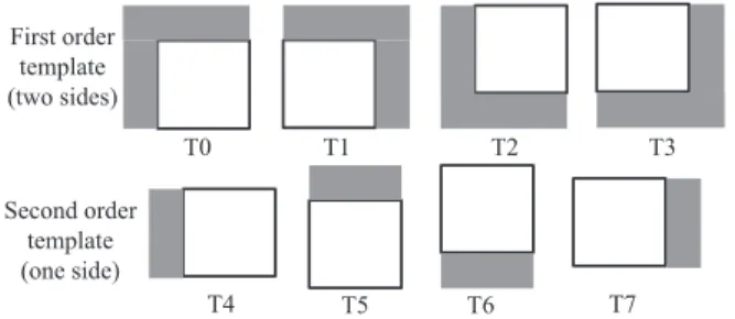
with respect to the total number of pixels within the block plus its templateΨB+T. The template can have different shapes and sizes,
henceΨT = ΨTi, i= 0 . . . N − 1 with ΨTi denoting one of the
shapes and sizes shown in Fig. 2. The confidence term C(ΨB) is
computed as:
C(ΨB) = card(ΨT)
card(ΨB+T)
(2) This term thus favors neighborhoods with a high number of known pixels.
The second term D(ΨB) gives the maximum strength of the
isophotes hitting all pixels on the front line separating the template and the block to be inpainted. This term is computed as
D(ΨB) = max(D(p), p ∈ δΩ ∩ ΨB+T) (3)
where D(p) computes on each pixel on the front line the inner prod-uct between the perpendicular to the image gradient and the normal to the front line as
D(p) = |∇I
⊥ p · np|
σ (4)
This term is higher when the isophote (the orthogonal to the gradi-ent) is perpendicular to the front line. The parameter σ is a normal-ization factor (e.g., σ = 255 for a typical grey-level image), and np
is a unit vector orthogonal to the front line δΩ in the point p.
T0 T1 T2 T3 T4 T5 T6 T7 First order template (two sides) Second order template (one side)
Fig. 2. Set of templates (in grey) used to compute the priority of a block (in white).
The parameter α controls the weight given to each of the terms C(ΨB) and D(ΨB). The priority function P (ΨB) is computed only
on the previously encoded pixels, which ensures that the same pro-cessing order can be derived at the decoder side without the need to transmit any side information.
Figure 3 displays an example of adaptive block processing order based on the proposed priority cost function.
t
…
Epitome (t=0)
Fig. 3. Example of adaptive block filling order on input image Bar-bara with the proposed epitome inpainting method.
3.2. Inpainting or prediction modes
The inpainting of the epitome is performed by propagating texture and structure using methods similar to intra prediction methods, adapted here to account for the fact that the blocks are not pro-cessed any more in a raster scan order. The methods used here are based on extended multi-directional H.264 Intra prediction modes in competition with extra modes based on block matching (BM) and LLE/oMALLE.
The H.264 directional modes have been adapted so that they fol-low the orientation of the template of the current block (see Fig. 2). Here we consider the four directions of the first order templates de-fined as T0, T1, T2 and T3 in Fig. 2. The direction of T1 is the one already used to define the directional modes in H.264. The modes associated to the three others directions are obtained by applying respectively three rotations of90◦,180◦and270◦on the classical
intra modes. Fig. 4 gives the directional modes obtained for the T1 template (upper right neighborhood). The BM algorithm does not rely on the template form so it is not affected. The only change is the shape of the search window SW that is defined in the causal part of the image. Similarly, the LLE-based method searches the K-NN blocks in the search window by computing distances between tem-plates [9], hence here with shapes which vary from one block to the other.
Fig. 4. Adapted directional modes for intra prediction with an upper right neighborhood.
Once the best mode has been selected and the prediction obtained, the residue of the block is computed, transformed, quantized and entropy coded with the H.264 encoding tools. At the decoder side the residue is obtained by inverse transform and dequantization. The block is immediately reconstructed by adding the decoded residue to the prediction. The reconstructed block is then available in the causal part of the image and the new front line is taken into account when computing the new filling order for the inpainting of the next block.
3.3. Integration in an H.264 codec
To validate the approach, the inpainting step has been integrated in an H.264 codec with the block size set to 8x8. The epitome is padded to fit with the 8x8 block grid and the prediction methods described above are applied. The best inpainting mode between H.264 ex-tended intra prediction modes, BM, LLE and oMALLE, is selected based on an RDO criterion.
However, the H.264 prediction step operates at a macroblock (MB) level. Hence, the algorithm inpaints the first8 × 8 block with the highest priority term within the macro-block. The processing order of the remaining blocks of the macro-block is then defined
according to the position of the first processed block and the orienta-tion of the causal neighborhood. The scanning order within the MB is obtained by applying three rotations of90◦,180◦and270◦on the
order defined in H.264 (see Fig. 5). Note that if several templates are available to encode a block within a MB, the same priority cri-terion as for the epitome inpainting is used to determine the one for encoding.
Finally the modification of the raster scan order implies major changes for the entropy coding (CABAC) for which the context has also been adapted.
0 1 3 2 2 0 1 3 1 3 2 0 3 2 0 1
Fig. 5. Scanning order within a MB. In grey is represented the causal part of the image neighboring the MB.
4. SIMULATIONS AND RESULTS
The algorithm was implemented in the Key Technical Area (KTA) software [19]. Objective assessments of the method were obtained using the Bjontegaard metric [20] at low (Quantization parameter (QP) = 26, 31, 36, 41) and high bitrates (QP = 16, 21, 26, 31). The method was tested on a set of four images: Barbara, Building, Spin-calendar and Wool.
First, the scheme based on epitome inpainting with in-loop residue encoding is compared to the classical H.264 intra coding scheme. Table 1 shows the Bjontegaard measures obtained with the priority order with α = 0.5 and α = 0.9 (Eq. 1). Results show a drastic reduction of the bitrate with an average of 32.34 percent of rate reduction at low bitrate and 21.99 at high bitrate when α= 0.5. The results are even better when α= 0.9.
Second, the method is compared to a modified H.264 codec in-tegrating the additional BM and LLE/oMALLE modes used with a raster scan order [10]. The performances of this reference modified codec are given in the column ”rster scan” of Table2 in comparison with a standard H.264 codec using Bjontegaard measures. The use of the BM and LLE/oMALE modes already gives interesting results with an average of33.54% and 22.28% of bitrate reduction at low and high bitrates respectively. However, one can observe an extra bit rate reduction when using the inpainting with the adaptive scanning order.
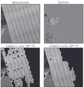
Figure 6 displays partially inpainted prediction images of Spin-calendar obtained at the same iteration but using two different QPs (i.e. different bit rates) to encode the residue. One can observe that at high bit rates, the image structures are obviously better recon-structed, hence lead to a different scanning order. However in both cases, overall, the scanning order follows the angles of the calendar strong edges.
5. CONCLUSION
In this paper we introduced a novel compression scheme that relies on the use of an epitome, different prediction methods such as BM, LLE and more importantly a new adaptive block processing order. This new block processing order allows a better adaptation to the content of the image that benefits the coding performances. The multi-patches methods such as LLE also greatly benefit from the use
Epitome
Adaptive scan, QP=16 Spincalendar
Adaptive scan, QP=41
Fig. 6. On top row: input image and its epitome. On bottom row: Prediction images during encoding, at the same iteration but differ-ent QPs.
Table 1. Comparison between the inpainting scheme integrated with neighbor embedding and H.264 intra modes
Adaptive Low bitrates High bitrates
scanning α = 0.5 α = 0.9 α = 0.5 α = 0.9
dB % rate dB % rate dB % rate dB % rate
Barbara 0.98 -14.43 1.13 -16.16 0.81 -9.37 0.92 -10.58
Building 4.16 -46.11 4.40 -48.12 4.33 -32.79 4.48 -33.89 Spincalendar 2.87 -37.28 3.15 -39.99 2.74 -27.61 2.97 -29.92
Wool 2.19 -31.55 2.33 -33.39 1.69 -18.21 1.81 -19.39
Average 2.55 -32.34 2.75 -34.42 2.39 -21.99 2.54 -23.44
Table 2. Comparison between the inpainting scheme integrated with neighbor embedding and H.264 intra modes with additional neigh-bor embedding
Low bitrates High bitrates
Raster scan Adapt. scan Raster scan Adapt. scan
dB % rate dB % rate dB % rate dB % rate
Barbara 1.19 -17.07 1.13 -16.16 0.92 -10.53 0.92 -10.58
Building 4.23 -46.78 4.40 -48.12 4.32 -32.80 4.48 -33.89 Spincalendar 2.87 -37.59 3.15 -39.99 2.64 -26.83 2.97 -29.92
Wool 2.28 -32.73 2.33 -33.39 1.76 -18.93 1.81 -19.39
Average 2.64 -33.54 2.75 -34.42 2.41 -22.27 2.54 -23.44
of the epitome. When introduced in an H.264 codec the method was shown to be very efficient especially at low bitrates with up to 48.12 % of bitrate saving.
6. REFERENCES
[1] N. Jojic, B. J. Frey, and A. Kannan, “Epitomic analysis of appearance and shape”, in Proc. IEEE Conf. Comput. Vis. (ICCV), 2003, pp. 34–41.
[2] H. Wang, Y. Wexler, E. Ofek, and H. Hoppe, “Factoring re-peated content within and among images.”, ACM Transactions on Graphics (Proc. SIGGRAPH), vol. 27, no. 3, Aug. 2008.
[3] B. Lucas and T. Kanade, “An iterative image registration tech-nique with an application to stereo vision.”, in Proceedings of Imaging Understanding Workshop, 1981.
[4] J. Shi and C. Tomasi, “Good features to track.”, in IEEE Conf. on Computer Vision and Pattern Recognition (CVPR), 1994. [5] D. Simakov, Y. Caspi, E. Shechtman, and M. Irani,
“Sum-marizing visual data using bidirectional similarity”, in IEEE Conf. on Computer Vision and Pattern Recognition (CVPR), 2008, pp. 1–8.
[6] Q. Wang, R. Hu, and Z. Wang, “Improving intra coding in H.264/AVC by image epitome”, in Advances in Multimedia Information Processing (PCM), 2009, pp. 190–200.
[7] Q. Wang, Z. Wang, and B. Hang, “Intra coding and refresh based on video epitomic analysis”, in IEEE Int. Conf. on Mul-timedia and Expo (ICME), 2010, pp. 452–455.
[8] S. Cherigui, C. Guillemot, D. Thoreau, and P. Guillotel, “Epitome-based image compression using translational sub-pel mapping”, in IEEE Int. Workshop on Multimedia Signal Pro-cessing (MMSP), Oct. 2011, pp. 1–6.
[9] M. Turkan and C. Guillemot, “Image prediction based on neighbor embedding methods”, IEEE Trans. on IP, vol. 21, pp. 1885–1898, 2011.
[10] S. Cherigui, C. Guillemot, D. Thoreau, P. Guillotel, and P. Perez, “Map-aided locally linear embedding for image pre-diction”, in IEEE Int. Conf. Image Process. (ICIP), 2012, pp. 2909–2912.
[11] T. Wiegand, G. J. Sullivan, B. Bjontegaard, and A. Luthra, “Overview of the H.264/AVC video coding standard”, IEEE Trans. Circuits Syst. Video Technol., vol. 13-7, pp. 560–576, Jul. 2003.
[12] T. Shiodera, A. Tanizawa, and T. Chujoh, “Bidirectional intra prediction”, in ITU-T SG16/Q.6 VCEG, VCEG-AE14, Mar-rakech, Morocco, January 2007.
[13] T. Palfner and T. Wedi, “Advanced scanning for intra frame coding”, in IEEE Int. Conf. Image Process. (ICIP), 2006, pp. 3121–3124.
[14] S.L. Yu and C. Chrysafis, “New intra prediction using intra macroblock motion compensation”, in JVT-C151, 3rd meeting of Joint Video Team (JVT), May 2002.
[15] S. Cherigui, C. Guillemot, D. Thoreau, P. Guillotel, and P. Perez, “Hybrid template and block matching algorithm for image intra prediction”, in IEEE Conf. Acoustics, Speech, and Signal Process. (ICASSP), 2012, pp. 781–784.
[16] T. K. Tan, C. S. Boon, and Y. Suzuki, “Intra prediction by template matching”, in IEEE Int. Conf. Image Process. (ICIP), 2006, pp. 1693–1696.
[17] T. K. Tan, C. S. Boon, and Y. Suzuki, “Intra prediction by aver-aged template matching predictors”, in IEEE Conf. Consumer Comm. Network. Conf. (CCNC), 2007, pp. 405–409.
[18] A. Criminisi, P. Perez, and K. Toyama, “Region filling and object removal by examplar-based image inpainting”, IEEE Trans. Image Proc., vol. 13-9, pp. 1200–1212, Sept. 2004. [19] “KTA Software, Ver. JM 14.2 KTA 1.0. Available:
http://iphome.hhi.de/suehring/tml/download/KTA/”.
[20] G. Bjontegaard, “Calculation of average psnr differences be-tween rd curves”, in document VCEG-M33, ITU-T VCEG Meeting, April 2001.