HAL Id: hal-02046029
https://hal.insa-toulouse.fr/hal-02046029
Submitted on 4 Mar 2019
HAL is a multi-disciplinary open access
archive for the deposit and dissemination of sci-entific research documents, whether they are pub-lished or not. The documents may come from teaching and research institutions in France or abroad, or from public or private research centers.
L’archive ouverte pluridisciplinaire HAL, est destinée au dépôt et à la diffusion de documents scientifiques de niveau recherche, publiés ou non, émanant des établissements d’enseignement et de recherche français ou étrangers, des laboratoires publics ou privés.
Incremental Modeling and Simulation of Mechanical
Power Transmission for More Electric Aircraft Flight
Control Electromechanical Actuation System
Application
Jian Fu, Jean-Charles Maré, Yongling Fu
To cite this version:
Jian Fu, Jean-Charles Maré, Yongling Fu. Incremental Modeling and Simulation of Mechanical Power Transmission for More Electric Aircraft Flight Control Electromechanical Actuation System Applica-tion. ASME 2016 International Mechanical Engineering Congress and Exposition, Nov 2016, Phoenix, United States. �10.1115/IMECE2016-66436�. �hal-02046029�
INCREMENTAL MODELING AND SIMULATION OF MECHANICAL POWER
TRANSMISSION FOR MORE ELECTRIC AIRCRAFT FLIGHT CONTROL
ELECTROMECHANICAL ACTUATION SYSTEM APPLICATION
Jian FU1,2, Jean-Charles MARÉ2, Yongling FU1
1. School of Mechanical Engineering & Automation, Beihang University
Beijing, China
2. Institut Clément Ader (ICA, CNRS UMR 5312), INSA-Toulouse, Université de Toulouse
Toulouse, France
ABSTRACT
In the field of more electric aircraft, electromechanical actuators (EMAs) are becoming more and more attractive because of their outstanding benefits of aircraft fuel reduction, maintenance costs saving, and system flexibility improvement. For aerospace electromechanical actuator applications, mechanical power transmission is critical for safety, in which reflected inertia to load, heat generated by energy losses and faults due to jamming, free-play and free-run are specific issues. According to the system-engineering process and simulation-aided design, this communication proposes an incremental approach for the virtual prototyping of EMA mechanical power transmission. Resorting to the Bond-graph formalism, the parasitic effects are progressively introduced and realism of models is increased step-by-step. Finally, the numerical implementations are presented and compared with basic, advanced and full models of mechanical power transmission in AMESim environment. Multi-level submodels are available and can be re-used for preliminary sizing, thermal balance verification and response to fault analysis. NOMENCLATURE
CbCmCjCs
Bearing translation support, motor electromagnetic, nut-screw inertial, rod output to surface torque [N/m]
F0 Preload force [N]
FbFcFdFe Bearing support translation, compliance contact, damping,
elastic force [N]
Fex, External aerodynamic force [N]
Ff Ff* Ff
Initial normal, faults injections and temperature sensitivity friction force [N]
FL Load force [N]
FmFs Motor shaft output, rod output to surface force [N]
jam
F Jamming stiction force [N]
fv Viscous friction coefficient [N/(m/s)]
ImIs Motor windings, DC supplied current [A]
PdPf Damping, friction loss [W]
S Heat power [J/sK]
UmUs Motor wingdings, DC supplied voltage [V]
vbvevrvsvsr
Bearing support, elastic, relative, rod output to surface, relative rod/support translational velocity [m/s] x0x*0 x0
Initial normal, faults injections, temperature sensitivity backlash/preload parameter [m]
xc Position command [m]
xw Wear parameter of nut-screw [m]
xr Relative elastic deformation [m]
f f Initial, temperature sensitivity friction factor[-]
x
Temperature dependency backlash/preload parameter [-]
di Efficiency direct, indirect [-]
Temperature [°C]
bmnsr
Support rotational, motor rotor, relative nut/support, relative rod/support angular velocity [rad/s]
i Current/torque loop angular frequency [rad/s]
EHA Electro-hydrostatic actuator
EMA Electro-mechanical actuator
EM Electric motor
HSA Hydraulic servo actuator
MPT Mechanical power transmission
PDE Power drive electronics
INTRODUCTION
Safer, cheaper and greener technologies are important initiatives for the next generation air transport in upcoming decades. In response to these needs, the aerospace industry is looking for an innovation (incremental or disruptive) in safety-critical actuation systems. In recent years, a significant interest is towards “more electric aircraft”. The trend is to increase the usage of power-by-Wire (PbW) electrical actuators: electro-hydrostatic actuator (EHA) and electro-mechanical actuator (EMA). These are envisioned to take the place of conventional hydraulic servo actuators (HSA). Compared to EHAs, EMAs totally remove the central and local hydraulic circuits, resulting in increased economic, competitive and environmental
Proceedings of the ASME 2016 International Mechanical Engineering Congress and Exposition IMECE2016 November 11-17, 2016, Phoenix, Arizona, USA
advantages [1]. EMAs have already served in a few secondary flight controls and for landing gear braking [2]. However, the maturity level of EMAs technology for primary flight control is far behind that of HSAs because of several potential issues: huge reflected inertia for dynamic performance, heat rejection for thermal balance and response to fault (jamming or free-play) for failure. Therefore, EMAs still suffer from key issues that put them aside from being employed front line (normal or active mode) in safety-critical applications.
In this situation, for assessment of concepts during the preliminary design stages, as well as for performance virtual verification, system-level modelling and simulation has become well established. Despite the wide availability of commercial simulation software, it appears that there is a lack of methodology for the structuration of models. This particularly concerns the continuity between engineering activities, the knowledge capitalization, and the multi-physic nature of actuation. Therefore, it has become mandatory to compensate this lack by resorting to a model-based system engineering (MBSE) approach. This approach enables engineers with efficient means to access performance through virtual means and to increase maturity, performance and robustness. This communication applies to mechanical power transmission (MPT), which is a key part of EMAs. The designers and manufacturers must consider with great care the parasitic effects resulting from the imperfections of technology: friction, backlash, compliance, etc., and these considerations are especially true for safety-critical embedded power systems:
-consideration of energy losses for energy/power consumption and thermal balance;
-coupled and nonlinear effects, e.g. influence of temperature, influence of pre-loading on friction, influence of service on preload or backlash;
-fault injections are considered for response to fault and fault-to-failure mechanism.
The following sections describe the power flows and multi-domains disciplines in EMA system. By using system-engineering (SE) processes and simulation-driven design (SDD) [3], MPT modeling is addressed to the current engineering activities and driven by requirements from engineering needs. Based on Bond-graph formalism, the replaceable, incremental and generic MPT models are developed by progressive levels of representativeness [4]. Starting form a functional model that only considers the physical effects combined to perform the function, imperfections of technologies are progressively introduced as parasitic effects in the advanced and full MPT models. At last, these proposed models are implemented in causal simulation environment of AMESim and numerical simulations are compared and analyzed.
EMA SYSTEM DESCRIPTION
In this communication, a typical direct drive linear EMA is considered, in which the rotating nut of mechanical power transmission is directly integrated as part of the electric motor rotor. Due to elimination of the intermediate gear box, it is a
compact design, and this “in-line” EMA is more attractive than geared EMA for aerospace application, thanks to the weight reduction and easy geometrical integration with-in the airframe. The EMA is developed for flight control application to drive a surface according to the pilot/autopilot commands, as described schematically in Fig. 1. Motor Sensor Control surface Position demand Nut-screw Motor Power Drive Electronics Velocity loop Cycles rates of PWM Electric Power Power Drive Electronics EMA Sensor Position loop Current loop surface angle Faults info. Aerodynamic effort Airframe Airframe Aircraft response Flight Control Computers (FCC) (Auto)pilot command ACE
FIGURE 1. SCHEMATIC STRUCTURE OF AN EMA ACTUATION SYSTEM.
The conventional architecture of an “in-line” EMA includes one electrical motor (EM) that converts the electric power into mechanical one, then the mechanical power transfers from rotation to translation domain through a nut-screw to move the control surface. Typically, the control of such an EMA is based on three main electronics devices. a) The flight control computers (FCC) ensure that the surface
position corresponds to the flight law commands. Also for monitoring purpose, the treatment of faults monitoring from the actuator is completed by the FCC.
b) The EMA actuator control electronics (ACE) receives the EMA position order from the FCC, sensor information from the EMA and processes an associated control loop. Usually, EMA control involves a rod position (outer loop), speed loop (middle loop) and a motor current/torque inner loop, for meeting the performance and stability requirements. ACE internally generates the pulse width modulation (PWM) command for the power drive electronics (PDE), as an image of the torque reference.
c) The PDE is integrated near the EM in the EMA; modulated electric power forms the aircraft network to an EM.
Cross-linked Multi-domain Disciplines
Designing an EMA system requires multidisciplinary approaches not only for preliminary power sizing and estimation of the mass and geometrical envelope, but also for design consideration of thermal behavior. It is well known that the PDE produces conduction and switching losses in electrical domain, the EM produces copper loss and iron losses in electrical and magnetic domains and the MPT produces friction loss in mechanic domain. Unlike a HSA, where the fluid power also has a cooling effect, an EMA system is a thermal closed-circuit system. The heat generated by all mentioned power losses, is over dissipated towards the local environment. This may increase the EMA operating temperature and bring snowball effects within all the devices. By the above analysis based on Bond-graph theory [5], the
disciplines involved by EMA are steady in cross-linked multi-domains, as shown in Fig. 2.
Electrical EMA Mechanic Control Thermal Magnetic voltage,U current,I force,F linear velocity,V temperature, entropy flux,Ṡ magnetomotive force,Em magnetic flux, torque,C rotation velocity,
FIGURE 2. MULTIDISCIPLINARY DOMAIN COUPLING IN EMAS.
Functional Power Flow Analysis
In a direct drive linear EMA, there exists two functional types of motion on the same axis: rotation of the EM rotor, and translation of the MPT rod. An idea for virtual prototyping of EMAs is to make the same topology models as the sectional view of product geometrical arrangement. Figure 3 illustrates the proposed architecture and the corresponding functional power flow in an EMA model based on the Bond-graph formalism [5]. The EM has been studied and presented in [4]. The modelling of MPT is based on two degrees of freedom (2-DoF) approach [6], but developed as an integrated model, in which the nut-screw, bearings (cylinder pairs), joints (hinges), shaft and end-stop are considered at the location of their power path.
Electric Motor (EM)
Housing with thermal model
Airframe To ambiance F V C T Ṡ Um Im Ṡ Rod To surface Fs Vs C Ft Vt C Housing Rod Control Mechanical Power Transmission (MPT) F V C Ṡ Cm m
FIGURE 3. POWER FLOW IN A SIMPLIFIED TOPOLOGY STRUCTURE OF EMA.
In this concept of MPT, the thermal balance is considered, and the functions of rod anti-rotation and rotor axial thrust bearing are explicitly modeled. In the figure 3, for simplified thermal behavior study, EMA housing is assumed as the major and unique thermal body that receives the heat generated by power losses from EM and MPT and exchanges with the ambiance. The following achievements presented in this paper will focus on the MPT subsystem of the EMA.
TABLE 1. MODEL ARCHITECTURES VS ENGINEERING NEEDS.
Model architectures
Engineering needs
No
parasite Power sizing Thermal balance dynamic Natural Stability accuracy Consumed energy response Failure propagation Reliability Load
Functional model
perfect transformer (TF) Y Y Y Y Y Y Y Y Y
Basic model
inertia/mass (I) N/A Y N/A P Y Y N/A P P
simple friction (RS) N/A P N/A P Y Y N/A P P
simple compliance (C) N/A P N/A P Y P N/A P P
Advanced model
modulate friction (MRS) N/A Y Y Y Y Y Y Y P
modulate compliance (MC) N/A Y Y Y Y Y Y Y P
Full model
failures injection N/A P N/A Y Y N/A Y Y Y
support interfaces N/A P N/A N/A P N/A N/A Y P
Note: Y means yes; P means possible, but depends on relative level; N/A means not applicable Model Architectures versus Engineering Needs
In order to follow the system engineering (SE) process, the system-level EMA modeling and simulation should consider
the physical effects at the right level of model complexity to meet the different engineering needs. From an engineering point of view, the best model of the technological device is usually not the most detailed one. In order to facilitate the
numerical implementation and avoid hard nonlinearities and discontinuous effects, in some cases, the parasitic effects that weakly impact performance are neglected. In this manner, the above mentioned ideas are applied to the example of MPT. Table.1 shows that the MPT model architectures are driven by engineering needs and in support of the whole EMA system virtual prototyping.
Incremental Multi-level Modeling
The physical effects in MPT are mainly belonging to the mechanical domain, and some of them are coupled with nonlinear thermal behavior (e.g. temperature sensitivity). To address the requirement-based model development, an incremental modeling approach using the Bond-graph formalism is proposed, which step-by-step combines the parasitic effects (resistance, capacitance, inertance and etc.) and progressively increases the MPT model complexity (from functional to full, from linear to nonlinear, from continuous to discontinuous). All introduced multi-level models of MPT are scalable and replaceable (as far as possible) with common interfaces (power and signal).
m
Cm
Vs
Fs
FIGURE 4. SCHEMATIC OF A MPT MODEL (NUT-SCREW) [7].
BOND-GRAPH MODELING OF MPT
In direct drive linear EMAs, the MPT appears as a rotary to linear power transformer. This transformation is obtained, in this example, by using a key component: the nut-screw. It aims at converting the rotational velocity and torque of the EM into linear speed and force for driving the load, as shown in Fig.4.
For lumped-parameter modeling of the MPT and according to the candidate location of the generic effects considered, the proposed decomposition involved five effects in series from motor to surface, as shown in Fig.5: a global inertia, a perfect nut-screw, a friction loss, a compliance effect (that can represent backlash, preload, or pure compliance), and a global mass. In the proposed MPT architectures, friction and compliance effects are the most significant, and can be modeled at different levels of complexity (linear/nonlinear and continuous/discontinuous). Inertia and mass effects in the MPT can be optionally neglected or modeled depending on the order of the EM rotor and surface ones. The effects of the bearings, joints and end-stop will not be explicitly modeled but can be considered to make part of the MPT model. Consequently, the proposed generic model of the MPT involves four mechanical power ports (rotation and translation of nut and screw). An additional thermal power port enables the MPT to output the heat generated by its power losses. For advanced MPT models, the heat port provides the temperature that enables reproducing its influence on friction and compliance.
Perfect nut-screw Friction Compliance
Power losses for heat vm s vs Fm Fs Cs m Cm Motor Surface
Nut-support support
Screw-MPT
Inertia Mass
FIGURE 5. PROPOSED ARCHITECTURE OF A MPT FOR BOND-GRAPH MODELING.
Functional Model
According to the above mentioned incremental approach, the MPT can be first expressed as a functional model with no parasitic effect. A TF element with causality in Bond-graph is shown in Fig.6, in which the power flow is considered:
TF
p/2p Perfect nut-screw Torque from motor Force to surfaceC
m
mF
sv
sFIGURE 6. FUNCTIONAL MODEL OF MPT IN BOND-GRAPH.
The perfect nut-screw model achieves pure power transformation of ratio (2p/p), where p is the screw pitch.
2 s m F C p p (1) 2 s p m v p (2)
In the proposed causality, nut-screw receives the effort of torque (Cm) from EM and transfers the effort of force (Fs) as
output to drive the surface.
Basic Model
This modelling level aims at increasing realism while being linear for control design activities. In this level of
modeling, three major parasites are introduced: the screw inertia (Js), the viscous friction loss (fe), and the basic
compliance effect including the contact elastic force (Fe) and
damping force (Fd). Corresponding Bond-graph model is
shown in Fig.7, in which the proposed causalities keep the same interfaces of the power and signal ports as that of the previous functional model.
Torque from motor Cm m
1
TF Perfect nut-screw1
0
1
p/2p MC: ke Compliance Stiffness Damping R: de R: fe Friction I: Jn Inertia Fs vs Cn m Cj m Fn vr vr vr Fr Fe Fc ve to surfaceForceFIGURE 7. BASIC MODEL OF MPT IN BOND-GRAPH.
Inertia Effect: Jn is the screw inertia, I element in the
Bond-graph, which generates an inertial torque:
n j n d C dt (3)
Generally, the screw inertia, like the roller-screw type direct drive EMAs, is small enough when compared to the rotor/nut inertia. It can be neglected or integrated with respect to the rotor/nut as an overall inertia effect for MPT.
Friction Effect: In MPT, there are several solutions to model the friction loss: consideration of velocity, external load force and operating temperature sensitivity [8]. From control engineer’s point of view, the simplest one is to describe the friction loss that is proportional to the operating velocity, which is affected by a viscous coefficient (fe), given by:
f v r
F f v (4)
Compliance Effect: Within EMAs, the MPT is not infinitely rigid. This makes it compliant due to the elastic deformation (xe) of solids under mechanical stress, in particular
at contact locations. A simple compliance model consists of a pure spring (ke) and damping (de) effects. The contact elastic
force (Fe) can be expressed as:
e e r
F k x (5)
Although the compliance damping is low, it must be considered in parallel with compliance in order to avoid unrealistic simulated oscillations. As the physical knowledge is very poor, the damping force (Fd) is usually considered as a
linear function of the relative velocity (ve), and of damping
coefficient (de).
d e e
F d v (6)
Advanced Model
This advanced level of MPT modeling is designed to offer high realism. In this manner, confidence is improved. For example, Energy balance studies are consistent from the energy balance point of view. Firstly, the nonlinear friction model (influence of velocity, load force and temperature) is upgraded to a modulated resistance element (MRS) in Bond-graph as it dissipates power. The nonlinear compliance model (pure spring,
backlash and preloading effects), is considered as modulated capacitance element (MC). Then the mechanical power losses of friction (Pf) and compliance damping (Pd) can be introduced
by the heat flows and connected to an additional thermal port. Consequently, it can easily enable the temperature to be used as a time variable input in the models of energy losses. Finally, the proposed MPT model architecture in this level involves a thermal port to be connected with EMA thermal model. The heat generation can be thought as an output to further EMAs’ thermal model for whole system energy balancing. Thus the temperature sensitivities to the friction model and to the compliance model (dilatation) can be modelled using the temperature variable provided by the thermal port. Figure 8 describes the Bond-graph modeling of this advanced MPT model. Causalities are kept consistent with the two previous levels models. Torque from motor Cm m 1 I: Jn TF Perfect nut-screw 1 To thermal model 0 1 p/2p MC: (ke , x0) De Compliance Dilatation De Stiffness Damping Load force Temperature sensitivity S 0 RS Friction losses MRS Friction Inertia Force to surface Fs vs Cn Cjm m Fn vr Fe vr vr Fr Fc ve
FIGURE 8. ADVANCED MODEL OF MPT IN BOND-GRAPH.
Nonlinear Friction Effect: The friction model can be built considering whether that function is velocity and load dependent, or load dependent and load independent [9].
-Velocity and load dependent: for nut-screws, a five parameter model, Eqn.(7), has been identified by Karam [10]. The friction force introduces a constant Coulomb friction (first part), a Stribeck effect of rapid change of friction at low velocity (second part), and a load and power quadrant dependent Coulomb effect (last part):
( sgn( ) sgn( ) r st v v f cl st L L r r F F F e F a b F v v (7)
-Load dependent and load independent: this model is consistent with nut-screw suppliers datasheets, which provide efficiency (the load dependent friction), as well as the no-load friction under opposite load and the no-drive friction under aiding load (the load independent friction). The velocity effect is added in a second step by introducing its influence of these parameters. The details of this modeling approach has been presented by author in [9].
For any friction model in MPT, the power loss (Pf) is
calculated as
f f r
P F v (8)
Nonlinear Compliance Effect: From a mechanical engineer’s point of view, obtaining a realistic model of compliance is of particular importance because compliance can significantly influence the low-magnitude dynamic performance [11] and the service life of the EMAs. Backlash or
preload are two key effects in a realistic compliance model. In the absence of preload and backlash, the axial mechanical stiffness will suffer from such a reduced stiffness around the null transmitted force where not all the contacts are fully loaded, this generates the so-called “lost motion”. Figure.9 shows the elastic characteristics of proposed compliance model (either pure spring, backlash or preload) and introduced by a single parameter x0: x0 -x0 x0> 0 x0< 0 x0= 0 xr Fe -F0=-kex0 backlash: 2x0 preload preload ke F0=kex0 preload backlash pure spring
FIGURE 9. ELASTIC CHARACTERISTIC OF PROPOSED COMPLIANCE MODEL.
-Pure spring effect: used when x0= 0, the contact force Fc
is purely proportional to the relative displacement xr
e e r
F k x (9)
-Backlash effect: used when x0> 0, model that displays a
total dead-zone of 2x0and the contact elastic force (Fe) is 0 0 0 ( ) , 0 , ( ) , e r r e r e r r k x x x x F x x k x x x x (10)
-Preload effect: used when x0< 0, where the preload force
is F0 k xe and the elastic force (Fe) is 0 0 0 ( ) , 2 , ( ) , e r r e e r r e r r k x x x x F k x x x k x x x x (11)
For numerical stability and rapidity, it is proposed to implement the compliance model by combining Eqns.(9) to (11) in such a way soas to avoid switches or “if” functions:
0 0 0 (1 ( ) ( ) 2 ( ) 1 ( ) 2 r r r e r r x x sign x x sign x F k x sign x sign x x (12)
Most of the common contact models implemented in simulation SW fail to avoid discontinuity of contact force when
the contact is reached or lost. This is due to the damping effect that is not implemented with care (damping force is null on reaching the contact and contact force is never attractive). Thus the damping force Fdcan be modeled in an advanced manner as
a force which is acting in parallel with the elastic force under the following constraints:
0 0 0 min( , ) , 0 , max( , ) , e e e r d r e e e r F d v x x F x x F d v x x (13)
The power loss due to compliance damping (Pd), although
negligible in general, can be calculated to make the MPT model exactly balanced with respect to energy:
d d e
P F v (14)
Temperature Sensitivity: In MPT,temperature influences friction due to viscosity effects and dimensions due to dilation. -Influence on friction: as it is well known, most EMAs’ MPT are grease lubricated. High temperatures lowers the viscosity of lubricant, resulting in increment of the friction loss. However, the effect of temperature on friction is poorly documented in the nut-screw suppliers’ datasheets. At system-level modeling, several models have been proposed by author
in [9]. As a consequence, a linear or nonlinear
parameter/function (f
a consequence, a linear or nonlinear ) can be introduced to modulate the friction force: ( vr st ( sgn( ) sgn( )) f f cl st L L r r Ff f FclF est F a b F v v Ff f Fcl F est F a b F v v Fffff ffff Fclclclcl F estststst F a b F v v Fff ff Fclcl F estst F a b F v v Ff f Fcl F est F a b F v v F F F e F a b F v v Ff f Fcl F est F a b F v v Fff ff Fclcl F estst F a b F v v Ff f Fcl F est F a b F v v F F F e F a b F v v F F F e F a b F v v F F F e F a b F v v Ff f Fcl F est F a b F v v Fff ff Fclcl F estst F a b F v v Fff ff Fclcl F estst F a b F v v Fff ff Fclcl F estst F a b F v v Ff f Fcl F est F a b F v v Fff ff Fclcl F estst F a b F v v Ff f Fcl F est F a b F v v F F F e F a b F v v Ff f Fcl F est F a b F v v Fff ff Fclcl F estst F a b F v v Ff f Fcl F est F a b F v v F F F e F a b F v v Ffff fff Fclclcl F eststst F a b F v v Fff ff Fclcl F estst F a b F v v Fffff ffff Fclclclcl F estststst F a b F v v Fff ff Fclcl F estst F a b F v v Ff f Fcl F est F a b F v v F F F e F a b F v v F F F e F a b F v v F F F e F a b F v v Ff f Fcl F est F a b F v v Fff ff Fclcl F estst F a b F v v Fff ff Fclcl F estst F a b F v v Fff ff Fclcl F estst F a b F v v Ff f Fcl F est F a b F v v F F F e F a b F v v F F F e F a b F v v F F F e F a b F v v Ff f Fcl F est F a b F v v Fff ff Fclcl F estst F a b F v v Fff ff Fclcl F estst F a b F v v Fff ff Fclcl F estst F a b F v v Ff f Fcl F est F a b F v v (15)
-Influence on dimension: in MPT, especially for roller type, the nut-screw has a very small lead. The thermal expansion may cause the thermal dilatation. This leads to variation of dimensions and may impact backlash, preload and friction. Once again, if a model of dilation is developed, this effect is easily introduced by using the temperature variable of the MPT thermal port. For example, the temperature effect on the value of the backlash parameter x0 can be a linear or nonlinear
parameter/function (x
of the backlash parameter
), and to describe the relative dilatation effect, following formula can be adopted:
0 (1 x ) x0 0 (1 ) 0 0 (1 ) 0 0 0 0 0 0 0 0 (1 ) 0 0 0 0 (1 ) 0 0 0 0 0 0 0 0 0 0 0 0 (1 ) 0 0 0 0 (1 ) 0 0 0 0 0 0(1(1 )) 0 0 (1 ) 0 0 0 0 (1 ) 0 0 0 0 (1 ) 0 0 0 0 (1 ) 0 0 0 0 (1 ) 0 0 0 0 (1 ) 0 0(1(1(1(1 )))) 0 0 (1 ) 0 0 0 0 (1 ) 0 0 0 0 (1 ) 0 0 0 0 (1 ) 0 0 0 (16) Full Model
This full model available involves mechanical faults (e.g. jamming and free run) and parasitic motion (relative displacement because of bearings and joints), shown in Fig.10.
0 Nut housing TF Perfect nut-screw 1 Screw housing To thermal model 0 1 p/2p De Compliance Fs Vsr Force to surface De Stiffness Damping Load force Temperature sensitivity 0 S 0 RS Friction losses MRS Friction Torque from motor Cm m 1 I: Jn Inertia Jamming Free-play /Wear Dilatation MC: (ke, x0) Fbvb Cbb Cn nr Cn n Fs Vs Fcve Ffvr Fn Vr Fe Vr Cjn
Mechanical Faults: It is definitely an added advantage when the model can reproduce the major faults that may occur in MPT. Jamming in MPT may jam the entire control surface. It can be modeled as a signal input to modulate the friction model parameters (MRS). If wear of the mechanical components will cause control surface free-play, this failure can be also modeled in a manner as signal modulates the model of compliance (MC): preload is reduced and backlash is increased by modifying parameter x0.
-Jamming to failure: it can be modeled as brake function by adding a stiction force to the friction model:
*
f jam f
F F F (17)
-Free-play or wear to failure: the compliance parameter x0
can be varied in the presence of increased backlash or decreased preload, which depends on the fault signal input:
*
0 0 w
x x x (18)
Parasitic Motion: Another highlight in this level of MPT’s architecture enables better modelling of mechanical interfaces: anti-translation function of motor/nut and anti-rotation function of rod/screw. In this way, it is possible to consider imperfect bearings and joints (e.g. compliance and friction) and to access the reaction torque (Cb) and force (Fb) to EMA housing or
airframe, and the relative rotational velocity (nr) for nut/rotor
and relative velocity (vsr) for screw to surface can be modeled.
-Support rotation: the relative rotational velocity between the rotor/nut and support bearings can be modeled as:
nr n b
(19)
-Support translation: the relative translational velocity between the screw and support bearings given:
sr s b
v v v (20)
All these advances proposed finally result in the two degrees of motion (2-DoF) MPT model, which can connect the bearings support interfaces.
IMPLEMENTATION OF MPT MODELS
For illustrating the interest of the proposed MPT model, the flight surface is subjected to the aerodynamic load. The control of the EMA is based on cascade multi-loops control architecture, shown in Fig 11. The PDE and EM are assumed to be perfect, the parasitic effects are neglected. Therefore, the PDE and EM are considered as a modulated source of effort: a second order function for PDE considering current/torque loop dynamics and a source effort of torque (Se) for the EM based on
Bond-graph modeling [4].
The proposed MPT multi-level models are independent, and replaceable (same input power port from the EM, and output power port to the surface). Although causal choices have been made, each architecture of MPT is adapted in causal (AMESim) and non-causal (Dymola) simulation environment.
EMA Controller
Rod position feedback
Xt m Position command Xc Velocity limit Kp KV
Motor velocity feedback
EMA Model implementation PDE + Motor dynamic MPT Cn n Fs vs Structural compliance Surface mass Aerodynamic force Fex Xs Load (surface) (Torque source) Xt EM rotor Cm m
FIGURE 11. SCHEMATIC DIAGRAM OF EMA SYSTEM FOR MPT MODELS IMPLEMENTATION
Basic MPT Model
The basic model is always simple, low order and linear. Its use is relevant for basic simulation and for preliminary control synthesis. According to Bond-graph model in Fig.7, the implementation of this basic MPT model in AMESim is shown in Fig.12.
( Motor rotor)
Perfect nut-screw Linear friction and
inertia integrated with rotor
Mechanism
stiffness Mechanism damping
Rod mass FIGURE 12. IMPLEMENTATION OF BASIC MPT MODEL
In this basic MPT model, all the components come from standard libraries. The motor rotor and nut-screw inertia are merged into a single lumped inertia on which applies a pure viscous friction. The motor power flows to a perfect nut-screw and is transmitted to the load through a compliance effect that
is considered using linear spring-damper model. At MPT interface with load, a rod mass is also considered.
Advanced MPT Model
According to the Bond-graph model in Fig.8, firstly, the former basic model of linear friction and compliance effects are replaced by more realistic models, Fig. 13.
Friction Stiffness Damping damper rate spring rate damping loss Compliance backlash Perfect nut-screw friction loss total power loss temperature sensitivity To thermal model load force rod mass summing force rotor inertia
In advanced MPT model, the proposed friction model of Eqn (7) is implemented by making the friction force dependent on transmitted force, temperature and sliding velocity (force and velocity are captured through sensors models). This dependence can be either defined by parametric functions or using loop-up tables. The compliance model of Eqn. (12) is implemented by moving to the “signal” world, separating explicitly the flow and effort variables though a standard AMESim model. Secondly, a standard AMESim thermal power bond is introduced. It collects the power losses (friction model and structural damping of compliance model) and inputs temperature to the friction (impact on friction factor) and compliance (impact on backlash) models.
Full MPT Model
Based on the Bond-graph model in Fig. 9, the implementation of full MPT model in AMESim is shown in Fig.14. The jamming and free-run faults are optionally introduced by external signal that affect the friction and compliance parameters, Eqns. (17) and (18), respectively. In addition, the relative rotational and translation positions between two mechanical components are available. Two mechanical ports associated with nut-housing for anti-translation and with screw-housing for anti-rotation, can be explicitly introduced for connection with the bearings and joints for 2-DoF modeling in future study.
Nut housing Perfect nut-screw Jamming Free-run To thermal model Friction stiffness total power loss compression rating friction loss damping load force damper rate Screw housing temperature sensitivity spring rate damping loss Compliance backlash 0 junction, sum of flow (rotational) 0 junction, sum of flow (translation)
(rotor) Rod mass
MPT Model To su rface Fr om EM
FIGURE 14. IMPLEMENTATION OF FULL MPT MODEL
NUMERICAL SIMULATION AND RESULTS
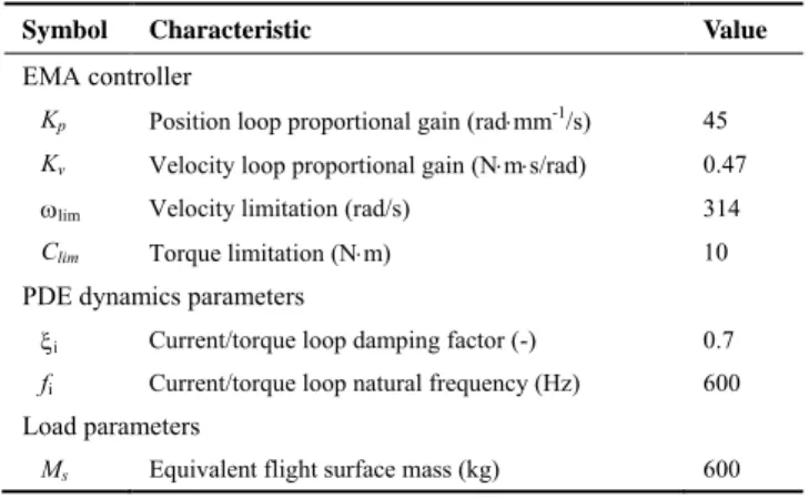
TABLE 2. EMA CONTROLLER, PDE, LOAD PARAMETERS
Symbol Characteristic Value
EMA controller
Kp Position loop proportional gain (radmm-1/s) 45
Kv Velocity loop proportional gain (Nms/rad) 0.47
lim Velocity limitation (rad/s) 314
Clim Torque limitation (Nm) 10
PDE dynamics parameters
i Current/torque loop damping factor (-) 0.7
fi Current/torque loop natural frequency (Hz) 600
Load parameters
Ms Equivalent flight surface mass (kg) 600
Source: i-product data[12],ii-scaled from former experiments[13],iii-literature[10]
TABLE 3. MPT PARAMETERS FOR FULL MODEL
Symbol Characteristic Value
Inertia effect i
Jn Nut-screw inertia integrated with rotor (kgm2) 0.0017
Mt Rod mass (kg) 1
Perfect nut-screw i
p Lead of screw (mm) 2.54
Friction effect ii
Fcl Coulomb friction force (N) 7590
Fst Stribeck friction force (N) -4702
vst Reference speed for Stribeck friction (m/s) 0.035
a Mean coefficient of external force (-) 0.218
b Quadrant coefficient (-) -0.13
Compliance effect iii
ke Elastic stiffness of nut-screw (N/m) 3108
Simulation parameters are shown in Tab.2 and Tab.3. The flight control surface is simply modelled as an equivalent translating mass (Ms) to which the air load is applied. In EMA
controller, the speed limitation (lim) and torque limitation
(Clim) are introduced. Gp(s) is the position controller and Gv(s)
is the velocity controller. In addition, the anchorage of the EMA housing to the wing and the EMA rod to load connection is all assumed to be rigid.
Interest for Control Design
An aileron position step demand of 10 mm is applied at time t=0.1 s, then followed by a step aerodynamic disturbance force of 10 kN at time t = 1 s. Figure 15 compares the load position simulated by the different MPT models (functional, basic and advance). Both simulated responses are stable. It can be seen that the realistic friction effect seriously increases EMA system damping and affects dynamic performances. Figure 16 displays that the motor torque/current is saturated for a longer time when a more realistic friction model is considered. Significant differences in response also appear at very low velocity. Force (kN) Load posi tion ( mm) Position demand MPT functional model MPT basic model MPT advanced model Disturbance force Position pursuit
detail Load rejection detail
FIGURE 15. DYNAMIC PERFORMANCES COMPARISON.
Time (s) Torque (N m) MPT functional model MPT basic model MPT full model
Very low speed (nearly null)
FIGURE 16. TORQUE SOURCE COMPARISON.
Interest of Power Consumption Analysis
The proposed full model of MPT can be used for comparative analysis of the power losses and energy consumption for whole EMA system. Figure 17 (A) shows the mission (Xc and Fex) and the load position response (Xs): A
trapezoidal position profile is demanded that of a maximum speed of 125mm/s. The external force is increased from 0 N at 0.1 s to 15 kN at t = 1 s. Focusing on MPT frictional loss, the losses of PDE and EM are adopted from advance model in Ref.[4]. It can be seen from Figure 17 (B) that when the final surface position is reached (no speed but high load), friction loss is null; high speed and high adding load has the highest power losses. The MPT friction loss represents the highest source (70%) of total energy losses, which highlights the importance to developan advanced friction model of MPT.
Position (mm) 75 -75 D t = 0.6s Time (s) Force (N ) Command signal Xc Surface displacement Xs External force Fex
(A) SPECIFIC MISSION PROFILE
Time (s)
Power (kW
)
DC network input EMA rod output
PDE losses (conduction and switching) EM copper losses
EM iron losses (eddy current and hystesis) MPT losses (friction and damping)
detail 3.5 3.0 2.5 2.0 1.5 1.0 0.5 0 1.50 1.54 1.58 1.62
(B) POWER CONSUMPTION AND LOSSES ANALYSIS FIGURE 17. EMA TOTAL POWER LOSSES (ADVANCED MODEL).
Interest for Wear/Ageing and Response to Faults
The analysis illustrates the interest of the proposed models for wear/ageing (increased backlash), and free-run or jamming faults. Figure 18 (A) compares the simulated responses of the MPT full model, and introduces the functions: null preload/backlash, (x0 = 0), a backlash (x0 = 0.1 mm), then a
the backlash makes surface chattering and impacts the position accuracy. The preload removes this effect (but increases friction) at the surface and affects the surface rapidity. Figure 18 (B) displays the simulated surface position when jamming is forced by adding a Coulomb friction (50 kN) at time a) 0.18 s (rise stage), b) 0.27 s (overshoot stage), c) 0.6s (stability stage) and d) 1.1s (rejection stage). As expected, the surface position is locked immediately.
Pure spring stiffness With 0.3mm backlash With 3kN preload Time (s) 0.22 0.28 0.34 Position (mm ) 10.3 9.9 9.5 Position ( mm) Time (s)
(A). WEAR/AGEING (BY BACKLASH OR PRELOADING)
Time (s) Jamming case 1 Jamming case 2 Jamming case 3 Jamming case 4 Jamming triggered Jamming triggered Jamming triggered Jamming triggered
(B). VARIOUS CASES OF JAMMING TRIGGERATIONS FIGURE 18. MPT FAILURES INJECTIONS (FULL MODEL).
CONCLUSIONS
An incremental modelling and simulation of mechanical power transmission has been proposed for supporting virtual prototyping of EMAs with a system-level view of MBSE design. Combining perfect nut-screw, parasitic effects (friction and compliance) and fault failures; the functional, basic, advanced and full models have been developed from the needs generated by engineering tasks and intends to use object-oriented elements and interfaces from standard model libraries. Each lumped-parameter model is energy balanced and mechanically replaceable (interface). It enables faults (jamming or free-play) to be simulated. The models are ready to be extended for next step thermal simulation and to be integrated
in full incremental realistic more electric aircraft virtual prototyping.
REFERENCES
[1] Botten, S. L., Whitley, C. R., and King, A. D., 2000, "Flight control actuation technology for next-generation all-electric aircraft," Technology Review Journal, 8(2), pp. 55-68. [2] Todeschi, M., 2010, "Airbus-EMAs for flight controls
actuation system-perspectives," International Conference on Recent Advances in Aerospace Actuation Systems and Components (R3ASC)Toulouse, France, pp. 1-8.
[3] Maré, J.-C., 2016, "Requirement-based system-level simulation of mechanical transmissions with special consideration of friction, backlash and preload," Simulation Modelling Practice and Theory, 63(2016), pp. 58-82. [4] Fu, J., Maré, J.-C., Fu, Y., and Han, X., "Incremental
modelling and simulation of power drive electronics and motor for flight control electromechanical actuators application," Proc. IEEE International Conference on Mechatronics and Automation (ICMA), pp. 1319-1325. [5] Karnopp, D. C., Margolis, D. L., and Rosenberg, R. C.,
2012, System dynamics: modeling, simulation, and control of mechatronic systems, John Wiley & Sons, New York. [6] Maré, J.-C., "2-D lumped paramaters modelling of EMAs
for advanced virtual prototyping," Proc. International Conference on Recent Advances in Aerospace Actuation Systems and Components (R3ASC), pp. 122-127.
[7] Cochoy, O., Carl, U. B., and Thielecke, F., "Integration and control of electromechanical and electrohydraulic actuators in a hybrid primary flight control architecture," Proc. International Conference on Recent Advances in Aerospace Actuation Systems and Components (R3ASC), pp. 1-8. [8] Maré, J.-C., 2012, "Friction modelling and simulation at
system level: a practical view for the designer," Proceedings of the Institution of Mechanical Engineers, Part I: Journal of Systems and Control Engineering, pp. 728-741.
[9] Maré, J.-C., 2015, "Friction modelling and simulation at system level: Considerations to load and temperature effects," J. Systems & Control Engineering, 229(1), pp. 27-48.
[10] Karam, W., and Maré, J.-C., 2009, "Modelling and simulation of mechanical transmission in roller-screw electromechanical actuators," Aircraft Engineering and Aerospace Technology, 81(4), pp. 288-298.
[11] Fu, J., Hazyuk, I., and Maré, J.-C., "Preliminary design rules for electromechanical actuation systems - effects of saturation and compliances," Proc. 5th CEAS Air & Space Conference.
[12] Exlar, 2014, "Exlar Product Catalog, GSX Series Integrated Motor/Actuator."
[13] Wang, L., and Maré, J.-C., 2014, "A force equalization controller for active/active redundant actuation system involving servo-hydraulic and electro-mechanical technologies," Proceedings of the Institution of Mechanical Engineers, Part G: Journal of Aerospace Engineering, 228(10), pp. 1768-1787.


![FIGURE 4. SCHEMATIC OF A MPT MODEL (NUT-SCREW) [7].](https://thumb-eu.123doks.com/thumbv2/123doknet/12249676.319938/5.918.82.804.478.794/figure-schematic-mpt-model-nut-screw.webp)