BIOMECHANICAL MODELING AND CHARACTERIZATION OF THE
POSTURAL PARAMETERS IN ADOLESCENT IDIOPATHIC SCOLIOSIS
SABA PASHA
INSTITUT DE GÉNIE BIOMÉDICAL ÉCOLE POLYTECHNIQUE DE MONTRÉAL
THÈSE PRÉSENTÉE EN VUE DE L’OBTENTION DU DIPLÔME DE PHILOSOPHIAE DOCTOR
(GÉNIE BIOMÉDICAL) AOÛT 2012
ÉCOLE POLYTECHNIQUE DE MONTRÉAL
Cette thèse intitulée:
BIOMECHANICAL MODELING AND CHARACTERIZATION OF THE
POSTURAL PARAMETERS IN ADOLESCENT IDIOPATHIC SCOLIOSIS
présentée par : PASHA Saba
en vue de l’obtention du diplôme de : Philosophiae Doctor a été dûment acceptée par le jury d’examen constitué de :
M. RAISON Maxime, Ph.D., président
M. AUBIN Carl- Éric, Ph.D., membre et directeur de recherche
M. MAC-THIONG Jean-Marc, Ph.D., membre et codirecteur de recherche M. MATHIEU Pierre A., D.Sc.A., membre
DEDICATION
To my parents, for their love and support.
ACKNOWLEDGMENT
I would like to first thank my research advisor, Professor Carl-Éric Aubin, who without his guidance and insights the presented thesis was not realized. I truly appreciate his effort to comprehend my idea and to lead me in the right direction. I would also like to thank my co-advisor, Dr Jean-Marc Mac-Thiong, for his clinical insights and genuine support of my work. I would like to thank Drs Hubert Labelle and Stefan Parent for all their constructive suggestions on my work during the last four years. I also would like to thank Dr Archana Sangole for her initiative role in my project. I would like to thank my colleagues at Sainte-Justine University Hospital and École Polytechnique particularly Drs Julien Clin and Eric Wagnac for all their technical help and consult. I would like to take the chance to acknowledge Dr Paul Allard’s collaboration in extensive sharing of lab facilities in Sainte Justine Hospital and Dr Marline Beaulieu who helped me with the data acquisition. I would like to thank Ms Julie Joncas, Ms Marjolaine Roy-Beaudry, Mr Christia n Bellefleur, and Mr Philippe Labelle who helped me to get the essential data for my project. I also appreciate the participation of all the patients and volunteers in Sainte-Justine Hospital in different parts of my research. A special thanks to all my friends in Montreal who made this period a very enjoyable time. Finally, I would like to thank our financial partners, Fonds de Recherche en Nature et Technologies (FQRNT), the Natural Sciences and Engineering Research Council of Canada (NSERC), and the ind ustrial chair with Medtronic.
RÉSUMÉ
La scoliose est une déformation 3D de la colonne vertébrale qui influence la morphologie et l'alignement de la colonne vertébrale, du bassin et de la cage thoracique. Bien que plusieurs paramètres soient introduits pour identifier et évaluer les courbes chez les sujets scoliotiques, la relation biomécanique entre la colonne vertébrale et le bassin ainsi que ses impacts sur la posture et l'équilibre général des sujets scoliotiques n’est pas encore élucidée.
Le but de ce projet doctoral était d'examiner l'interaction spino-pelvienne en mesurant les paramètres biomécaniques chez les sujets atteints de scolioses idiopathiques adolescentes (SIA). La cinématique pelvienne, l'orientation spino-pelvienne relative et le chargement biomécanique lombo-sacré ont été examinés chez des sujets avec des courbures différentes. L’hypothèse que nous souhaitons vérifier est que l'interaction spino-pelvienne (au niveau des paramètres statiques, cinématiques et des chargements biomécaniques à l’interface entre le rachis et le bassin) est non seulement différente entre les SIA et les contrôles, mais varie aussi entre les sujets présentant différents types de scolioses. De plus, l'effet d’une instrumentation chirurgicale du rachis sur l’équilibre ainsi que sur l'interaction biomécanique spino-pelvienne a été étudié post opérativement.
Donc, après avoir examiné la littérature pertinente, trois chapitres ont été consacrés pour examiner l'hypothèse générale de ce projet. Chaque chapitre aborde un aspect de l'interaction spino-pelvienne chez les sous-groupes scoliotiques et compare les résultats avec un groupe de contrôles de la même catégorie d'âge-sexe.
Bien que l'orientation pelvienne entre les sujets SIA et le groupe contrôle était différente, il n'est pas vérifié dans quelle mesure l'orientation pelvienne et l'alignement spino-pelvien affectent la cinématique du bassin chez les sujets présentant différents types de courbures. Par la suite, l’interférence entre l'orientation du bassin et le mouvement spino-pelvien a été étudiée. Un protocole expérimental a été conçu pour examiner le mouvement pelvien en 3D lors du mouvement du tronc in vivo. 17 sujets avec scoliose thoracique droite (TD), 8 sujets avec une scoliose thoracique droite et une courbure compensatoire lombaire gauche (TDLG), et 12 contrôles sans aucune histoire de maladie rachidienne ont été recrutés. Les sujets ayant reçu un traitement par corset ou chirurgical ont été exclus. Plusieurs marqueurs ont été attachés sur la peau à des points anatomiques spécifiques: acromions (pour définir la gamme tota le de
mouvement du tronc) et ASIS et PSIS gauches et droits pour analyser la cinématique pelvienne. Les mouvements de tronc, c.-à-d. la flexion/extension, la rotation axiale et la flexion latéra le ont été exécutés et ont été répétés trois fois pour chaque participant. Les coordonnées 3D des points anatomiques ont été engegistrées avec un système opto-électronique. Les amplitudes des mouvements pelviens (le ROM) dans les trois plans anatomiques ont été calculées et ont été comparées entre les trois groupes. D’après les résultats, l'orientation pelvienne était différente de manière significative pour les trois types de mouvement entre les groupes étudiés (p<0,001). La contribution du mouvement pelvien au ROM était différente dans les groupes étudiés. La pente sagittale pelvienne et la rotation axiale pelvienne étaient également significativement différentes entre les deux groupes de sujets scoliotiques (p<0,05). Les résultats ont montré que l'orienta tion initiale du bassin dans les trois plans anatomiques joue un rôle important dans la détermination de la contribution pelvienne au ROM maximum chez les sous- groupes scoliotiques.
Bien que le but principal du diagnostic et de l'évaluation de la scoliose consiste à déterminer la position et la sévérité des courbures spinales, les différentes études précédemment publiées ont montré la présence d'une déformation pelvienne significative chez les sujets avec une scoliose notamment dans le cas des courbures sévères. Toutefois, la relation entre la déformation pelvienne et les courbures vertébrales chez les sujets avec différents types de scoliose n'a pas encore été caractérisée. Afin d’établir cette relation, les images radiographiques latérales et postéro-antérieures de 80 sujets avec une courbure thoracique droite (TD), 80 sujets avec une courbure thoraco- lombaire/lombaire gauche (TL/L) et 35 contrôles ont été obtenues. La reconstruction 3D de la colonne vertébrale et du bassin a été produite en utilisant les images radiographies biplanaires de chaque sujet. L'orientation 3D du bassin a été mesurée en utilisant les coordonnées 3D des épines iliaques antéro-supérieures et postéro-supérieures (gauches et droites) (ASIS et PSIS). Un trapézoïde a été tracé en connec tant ces quatre points. L'angle entre les projections de la ligne qui joint le milieu de l'ASIS et PSIS sur chaque côté sur les plans sagittal, frontal et transverse et les axes horizontal et vertical ont été utilisés pour définir l’orientation pelvienne dans les plans sagittal et frontal et la rotation axiale pelvienne. L'orientation pelvienne moyenne (en valeur absolue) a été respectivement mesurée dans les plans frontal et transverse à 2° [plage 0°, 7°] et 4° [plage 0°, 10°] dans le groupe de TD et à 4° [ plage 0°, 8°] et 5° [ plage 0°, 11°] dans le groupe de TL/L. Alors que l’orientation frontale pelvienne correspondait à la position de la courbe vertébrale dans le plan frontal, c.-à-d. les courbures
thoracique et lombaire, plus de 70% des sujets scoliotiques dans chaque groupe ont leur courbure thoracique principale et leur bassin tourné dans la même direction dans le plan transverse (p<0,05). 91 % des contrôles ont moins de 1,8° d'obliquité pelvienne [0°, 3°] sur la vue postéro-antérieure avec une rotation axiale pelvienne non significative de 1,2° [0°, 3°] dans le plan transverse. Une corrélation significative a été trouvée entre l'orientation pelvienne et les déformations vertébrales thoraciques et lombaires dans les plans frontal et transverse pour les deux sous-groupes de SIA.
Il était également d'intérêt de montrer si l'orientation spino-pelvienne pour les sous-groupes de SIA interfère avec le chargement biomécanique du sacrum. Par conséquent, l'impact biomécanique de l'alignement relatif spino-pelvien sur le sacrum a été étudié. Un modèle par éléments finis (MÉF) a été développé pour calculer le chargement biomécanique du sacrum pour 11 scolioses TD, 23 scolioses TL/L gauche et 12 sujets contrôles. Les radiographies des sujets ont été utilisées pour développer les reconstructions 3D de la colonne, du bassin et de la cage thoracique. Les propriétés mécaniques des vertèbres, disques intervertébraux et ligaments et la position du centre de masse (CDM) au niveau de chaque vertèbre dans le modèle proviennent de données pertinentes publiées. La force de gravité a été appliquée à niveau de chaque vertèbre. Une méthode d'optimisation a été utilisée pour assurer la similarité maximale entre la reconstruction 3D à partir des radiographies et le MÉF après les simulations. Le chargement mécanique sur S1 a été calculé pour tous les sujets. Les forces de compression sur S1 ont été normalisées par rapport au poids du patient et ont été graduées entre les magnitudes maximale et minimale de la compression sur S1. La position du barycentre de la distribution des contraintes sur le sacrum (CDPS1) a été déterminée pour chaque sujet. D’après les résultats, la distribution
des contraintes compressives était différente de manière significative entre les contrôles et les sujets TL/L (p<0,05). Bien que la distribution des contraintes était symétrique pour les sujets TD et les contrôles, chez les sujets TL/L une contrainte plus élevée a été observée du côté gauche du sacrum comparé au côté droit. Les résultats montrent donc que le chargement biomécanique du sacrum a varié pour les sous-groupes de scoliose et les contrôles. Le chargement biomécanique du sacrum n'a pas été seulement affecté par la position de la courbure scoliotique majeure mais il a aussi été modifié par l'alignement relatif spino-pelvien pour les sous- groupes scoliotiques.
Bien que l'étude précédente a souligné l'effet de la déformation vertébrale sur le chargement biomécanique du sacrum pour les sous-groupes de SIA, l'effet de la position du
CDM sur les résultats de la simulation de MÉF n'a pas encore été déterminé. Afin de determiner la position du CDM chez un sujet scoliotique, une méthode mathématique a été développée. L'oscillation du centre de pression (le CDP) de 17 sujets TD et 4 sujets TDLG a été enregistrée au moyen de deux plaques de force pendant 30s en position début. La technique d'intégration double a été utilisée pour calculer la projection du COM sur le plan transverse au moyen de l'emplacement 2D de l'oscillation du CDP. Dans cette méthode, les intervalles entre lesquels la composante horizontale de la force de réaction du sol était égale à zéro étaient doublement intégrées pour estimer la position de la masse oscillante c.-à-d. le COM du sujet. Une analyse linéaire de régression a associé la position du CDP et la position 2D du CDM dans le plan transverse pour la cohorte de sujets scoliotiques. Cette équation a été utilisée pour transférer la position du CDP à la position de CDM dans les CDP-radiographies synchronisés qui ont été enregistrés pour neuf autres sujets scoliotiques. Une méthode d'optimisation a été appliquée pour calculer la position du CDM de chaque tranche de tronc dans les plans frontal et sagittal afin que la distance entre le CDM résultant de la méthode d'optimisation et le CDM de l'équation de régression soit minimisée. Les résultats de l'optimisation ont montré que la position nette du CDM après l'optimisation était plus proche du centre de la tête fémorale qu’avant l'optimisation (26% dans la position antéro-postérieure et 15% dans la direction médio- latérale). La position optimisée du CDM a été appliquée dans le MÉF et le chargement mécanique du sacrum a été recalculé pour les neuf sujets scoliotiques. Bien que la magnitude de la contrainte normalisée sur le sacrum ait été réduite après optimisation de la position du CDM, aucune différence significative n’a été observée au niveau de la tendance générale de la distribution de contraintes sur le sacrum. L'algorithme proposé a rendu possible l’évaluation de la position personnalisée du CDM au niveau de chaque vertèbre pour les sujets scoliotiques. La méthode proposée était applicable pour la simulation biomécanique du rachis scoliotique et a permis d'améliorer l'évaluation du chargement biomécanique de la colonne vertébrale dans les modèles ÉF des patients.
Enfin, une étude de cas a été effectuée pour analyser l'effet de la correction chirurgicale de la scoliose sur le chargement biomécanique du sacrum chez les sujets avec différents types de déformations scoliotiques. Cinq sujets TD et quatre sujets thoracique droit/lumbaire gauche (TD/LG) qui avaient subi leur première chirurgie avec un suivi moyen de 16 mois [12-18 mois] ont été choisis. Les radiographies biplanaires de 12 sujets asymptomatiques ont été ajoutées
comme le groupe contrôle. Plusieurs paramètres morphologiques et biomécaniques du rachis et du bassin (les angles de Cobb thoraciques et lombaires, cyphose, lordose, CDM, incidence pelvienne, la pente pelvienne, la pente sacrée et la position de CDPS1) ont été mesurés avant et
après l'opération pour tous les sujets scoliotiques. La corrélation entre les paramètres spinaux et pelviens a été calculée pour les contrôles et les sujets avec SIA pré- et post- opération. Comme les résultats l’ont indiqué pour la position du CDM et CDPS1, en plus des autres paramètres du
rachis, c.-à-d. les angles de Cobb thoraciques et lombaires, étaient significativement différents entre les groupes SIA et les contrôles avant opération (p<0,05). Après l’opération, les angles de Cobb thoracique et lombaire étaient différents de manière significative entre les groupes scoliotique et les contrôles (p<0,05). La position du CDPS1 était différente de manière
significative entre les sujets préopératoires et contrôles (p<0,05) alors qu'aucune différence n’a été observée entre les sujets contrôles et les sujets SIA après l’opération. Ces résultats montrent que la correction chirurgicale de la scoliose a tendance à normaliser les contraintes au niveau du sacrum. De plus, l'effet de la chirurgie d’instrumentation sur l’équilibre du chargement biomécanique du sacrum a été montré dans le groupe de sujets scoliotiques après la chirurgie.
En résumé, la thèse actuelle a examiné différents aspects de l'interaction spino-pelvienne pour les sous-groupes scoliotiques en 3D. Les résultats ont souligné les interactions biomécaniques entre le rachis et le bassin pour les sous- groupes SIA avant et après l’instrumentation chirurgicale. Considérer l'interaction relative spino-pelvienne comme une caractéristique de chaque sous- groupe de sujets scoliotiques pourrait s’avérer avantageux pour le traitement et la correction de la SIA.
ABSTRACT
Scoliosis is a 3D spinal deformity which impacts the morphology and alignment of the spine, the pelvis, and the ribcage. Although several spinal parameters are introduced to identify and evaluate scoliotic curves, there is not much known about the biomechanical relationship between the spine and the pelvis and its impact on the overall posture and equilibrium of the scoliotic patients.
The focus of this Ph.D. project was to investigate the spino-pelvic biomechanical interaction in adolescent idiopathic scoliosis (AIS) more closely. Spine and pelvic kinematic, relative spino-pelvic orientation in static, and lumbosacral biomechanical loading were investigated in subjects with different curve patterns. We hypothesized that spino-pelvic interaction is not only different between AIS and controls, but also varies between subjects with different scoliotic types in static, kinematic, and biomecha nical loading. Furthermore the hypothetical effect of the spinal operation on equilibrating the spino-pelvic biomechanical interaction was tested postoperatively.
Hence, after reviewing the pertinent literatures, 3 chapters were devoted to investigate the general hypothesis of this project. Each chapter tries to investigate one aspect of the spine and pelvis interaction in scoliotic subgroups and compares the results with an age-gender match group of controls.
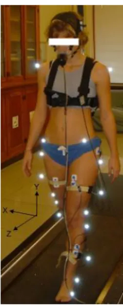
Although the pelvic alignment in the AIS group was different from the age-gender matched control group, it is not closely verified to what extent the pelvic orientation and the spino-pelvic alignment affect the pelvis kinematic in subjects with different curve types and subsequently its impact on the spino-pelvic movement is not determined. An experimental setup was designed to investigate the pelvic 3D motion during simple trunk movement in vivo. 17 right thoracic (RT), 8 right thoracic with compensatory left lumbar curve (RTLL) scoliosis, and 12 controls with no history of spinal disease were recruited. Subjects who had received any sort of treatment by spinal operation or bracing were excluded from the scoliotic group. Several skin markers were attached to specific anatomical landmarks: acromions (to define the total range of motion of the trunk) and left and right ASIS and PSIS to analyze pelvic kinematic. Simple trunk movements i.e. flexion/extension, axial rotation, and lateral bending were performed and repeated three times by each participant. Skin markers’ 3D coordinates were registered
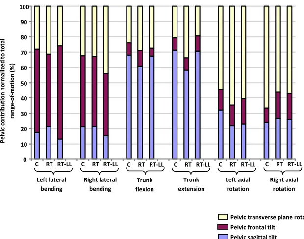
throughout the experience by an optoelectronic system. Pelvic range of motions (ROM) in the three anatomical planes were computed and compared between the three groups. Pelvic orientation was significantly different during three types of movement between the studied groups (p<0.001). Different pelvic range of motion in the anatomical planes was measured in the studied groups. Pelvic sagittal tilt and pelvic axial rotation were significantly different betwee n the two scoliotic groups (p<0.05). The result suggests that pelvic initial alignment in the three anatomical planes plays an important role in determin ing the pelvic contribution to the maximum ROM in the scoliotic subgroups.
Although the main focus in diagnosing and evaluating the scoliosis is on the location and severity of the spinal deformities, different published literatures have shown the presence of a significant pelvic obliquity or rotation in scoliosis particularly in subjects with severe curves. However, the relationship between the pelvic orientation and spinal curves in subjects with different types of scoliosis was not characterized yet in 3D. In order to investigate this relationship, the lateral and postero-anterior radiographs of 80 main right thoracic (MT), 80 left thoraco- lumbar/ lumbar (TL/L), and 35 controls were obtained. 3D reconstruction of the spine and pelvis was generated from bi-planar radiographs of each patient. Pelvic 3D alignments were measured by means of the 3D coordinates of the left and right anterior and posterior iliac spine landmarks (ASIS and PSIS). A trapezoid was schemed by connecting these four points. The angle between the projections of the line connecting the midpoint of the ASIS and PSIS on each side on frontal and transverse planes and true horizontal and vertical axes were used to define the pelvic frontal tilt, and pelvic axial rotation respectively. The average pelvic orientation (absolute value) was measured respectively in frontal and transverse planes at 2.6° 2 [range: -6°, 5°] and at 3.8° 2 [-7°, 8°] in the MT group, and at 3.2°1 [-8°, 4°] and at 4.4°2 [-10°, 10°] in the TL/L group. While pelvic frontal tilt correlated to the position of the spinal curve in the frontal plane (the thoracic and lumbar segments) more than 70% of the scoliotic subjects in each group had their main thoracic and pelvis rotated in the same direction in the transverse plane (p<0.05). 91% of the controls had less than 1.8° pelvic obliquity [0°, 3°] and a non-significant 1.2° pelvic axial rotation [0°, 3°] in the transverse plane. The results highlighted a significant correlation between pelvic orientation and both thoracic and lumbar spinal deformities in frontal and transverse planes in the two AIS subgroups.
It was also of interest to show the impact of the altered spino-pelvic orientation on the biomechanical loading of the sacrum in AIS subgroups. The biomechanical impact of the relative spino-pelvic alignment on the sacrum was studied. A finite element model (FEM) was de veloped to compute the sacral loading in 11 right MT, 23 left TL/L (thoracolumbar/lumbar), and 12 control subjects. The material properties of the vertebrae, intervertebral disks, and ligaments in the model and the position of the center of mass (COM) at the level of each vertebra were derived from the pertinent literatures. The gravitational force was applied at the COM of each vertebral level. An optimization technique was used to assure the maximum similarity between the 3D reconstruction of the digitized radiographs and the FEM after running the simulations. Mechanical loading on the S1 endplate was computed for all the subjects. Compressive stress on the S1 endplate was normalized to the patient weight and was scaled between the maximum and minimum stress magnitude on the S1. The position of the barycentre of the compressive stress distribution on the superior sacrum endplate (COPS1) was determined in each subject.
Compressive stress distribution on the sacrum was significantly different between controls and TL/L subjects p<0.05. Although sacral compressive stress distribution was symmetric in MT and controls, in TL/L higher stress was observed at the left side of the sacrum as compared to the right side. Biomechanical loading of the sacrum varied betwee n the AIS subgroups and controls. The biomechanical loading of the sacrum was not only affected by the location of the major curve but it was also modified by the relative spino-pelvic alignment in the scoliotic subgroups.
Even though the previous study highlighted the effect of the spinal deformity on the biomechanical loading of the sacrum in AIS subgroups, the effect of the position of the COM on the results of the FEM simulation was not determined yet. In order to determine the personalized position of the COM in a scoliotic subject a mathematical method was developed to estimate the 3D location of the COM at the level of each vertebra in the scoliotic spine. The developed method consisted of two sections: in the first experiment center of pressure (COP) oscillation of 17 RT and 4 RTLL was registered by means of two force plates during 30s of quite stance. Double integration technique was used to calculate the projection of the center of mass on the transverse plane by means of the 2D location of the COP oscillation. In this method the horizontal component of the ground reaction force was double integrated to estimate the location of the oscillating mass i.e. COM of the subject in the transverse plane. A linear regression analysis correlated the position of the COP and the 2D position of the COM in the transverse
plane in the cohort of subjects. This regression equation was used in the second experiment to transfer the position of the COP to the COM in a series of synchronized COP and X-ray data attained in 9 other AIS patients. An optimization method was applied to optimize the location of the COM of each trunk slice in the frontal and sagittal planes (from literature) in such way that the distance between the resultant COM from the optimization method and the COM from the regression equation was minimized. As the result of the optimization showed, the net position of the COM after optimization was closer to the midpoint of the femoral heads axis as compared to the same distance before operation. 26% dec rease in the anterior-posterior position and 15% decrease in the medial- lateral position in the distance between the COM and center of the femoral heads axis after the optimization process were calculated. The optimized position of the COM was applied in the FE model and the mechanical loading of the sacrum was calculated for the latter 9 subjects. Although the magnitude of the normalized stress on the sacrum was reduced after the optimization of the COM position in the FEM, no significant difference was observed in the general trend of the stress distribution on the sacrum. The proposed algorithm made it possible to assess the personalized position of the COM at the level of each vertebra in scoliotic subjects during routine clinical visits. The proposed method was applicable in the biomechanical simulation of the scoliotic spine and permitted to better analyze the biomechanical loading of the spine in patient-specific FE models.
Finally a case study was performed to analyze the effect of the spinal surgery on the biomechanical loading of the sacrum in subjects with different types of scoliosis. 5 right MT and 4 right thoracic/ left lumbar, who had undergone their first posterior spinal fusion with an average follow-up of 16 months [12-18 months] were selected. The bi-planar radiographs of 12 asymptomatic subjects were added as the control group. Several spine and pelvic morphological and biomechanical parameters (thoracic and lumbar Cobb angles, kyphosis, lordosis, pelvic incidence, pelvic tilt, sacral slope, and the position of the COM and the COP S1) were measured
before and after operation in all subjects. The correlation between spine and pelvic parameters were calculated in controls and pre- and post- operative AIS. The position of the COPS1 was
significantly different between pre-operative and control subjects (p<0.05) while no such difference was observed between the post-operative subjects and controls. The application of both spino-pelvic biomechanical and morphological parameters permitted to evaluate the biomechanical outcome of the surgical instrumentation of the spine. The effect of the spinal
surgery on equilibrating the biomechanical loading of the sacrum and making it more similar to the values observed in controls was shown in the post-operative group.
In summary, the current thesis investigated different aspects of the spino-pelvic interaction in selected scoliotic subgroups in 3D. The results highlighted the interactive relationship between the spine and pelvis in AIS subgroups before and after operation. Considering the spino-pelvic relative interaction as a characteristic of each scoliotic subgroup is beneficial in the treatment and assessment of the AIS.
TABLE OF CONTENTS
DEDICATION………….. ... III ACKNOWLEDGMENT ... IV RÉSUMÉ…………... V ABSTRACT……. ... X TABLE OF CONTENTS ...XV LIST OF TABLES ... XIX LIST OF FIGURES... XXI LIST OF SYMBOLS AND ABBREVIATIONS ...XXVINTRODUCTION... 1
CHAPTER1 LITERATURE REVIEW... 4
1.1 Descriptive anatomy and functions of the normal trunk ... 4
1.1.1 Spine ... 4
1.1.2 Pelvis ... 6
1.1.3 Anatomy of the sacrum ... 8
1.1.4 Anatomy of the sacroiliac joint (SIJ) ... 9
1.1.5 Sacroiliac joint function ... 9
1.1.6 Sacroiliac joint ligaments ... 10
1.1.7 Pelvic muscles ... 11
1.2 Scoliotic spine and pelvis... 13
1.2.1 Scoliotic spine deformities ... 13
1.2.2 Pelvic parameters in scoliosis ... 14
1.3 Spino-pelvic relative alignment ... 17
1.3.2 Spino-pelvic alignment in scoliosis... 19
1.4 Kinematic of the spine and pelvic in scoliosis ... 22
1.5 Center of pressure and center of mass ... 24
1.5.1 Center of pressure: Facts and measurement ... 24
1.5.1.1 Direct measurement of the COM………..…….24
1.5.1.2 Indirect measurement of the COM: Measurement of the COM via the position of the COP……….……….25
1.5.2 Center of pressure related stability measurement in control and scoliosis ... 28
1.6 Spinal equilibrium in scoliosis ... 30
1.7 Scoliotic spine modeling ... 31
1.8 Scoliotic spine biomechanics before and after spinal fusion and instrumentation ... 35
CHAPTER2 OBJECTIVES AND HYPOTHESES ... 37
CHAPTER3 PELVIC 3D KINEMATIC AND ORIENTATION IN ADOLESCENT IDIOPATHIC SCOLIOSIS ... 40
3.1 Presentation of the first article………..….…...40
3.2First article: Characterizing pelvis dynamics in adolescent with idiopathic scoliosis...41
3.2.1 Abstract ... 42
3.2.2 Introduction ... 43
3.2.3 Materials and Methods ... 45
3.2.3.1 Subjects……….….45 3.2.3.2 Statistical analysis………..…46 3.2.4 Results……….………..…………...….47 3.2.5 Discussion ... 49 3.2.6 Conclusion... 51 3.2.7 References ... 52
3.2.8 Figures and Tables ... 54
3.3 Analysis of the spino-pelvic relative orientation in scoliotic subgroups in the standing posture ... 58
3.3.1 Materials and Methods ... 58
3.3.1.1Subjects………...59
3.3.1.2 Pelvic orientation in the global coordinate system………....61
3.3.1.3 Pelvic orientation with respect to the thoracic and lumbar spinal deformities…..62
3.3.2 Results………..62
3.3.2.1 Pelvic orientation in the global coordinate system………....62
3.2.2.2 Pelvic orientation with respect to the thoracic and lumbar spinal deformities…..64
3.3.2.3 Impact of the reconstruction error on the pe lvic orientation: a sensitivity analysis …...……….…….65
CHAPTER4 FINITE ELEMENT ANALYSIS OF THE BIOMECHANICAL LOADING OF THE SACRUM IN ADOLESCENT IDIOPATHIC SCOLIOSIS... 67
4.1 Presentation of the second article………..67
4.2 Second article: Biomechanical loading of the sacrum in adolescent idiopathic scoliosis .... 68
4.2.1 Abstract ... 69
4.2.2 Introduction ... 70
4.2.3 Materials and methods ... 71
4.2.3.1Subjects………...………71
4.2.3.2 Measurement of the patient’s morphological parameters………..…71
4.2.3.3 Finite element modeling and simulation………74
4.2.4.1 Subjects………..…75
4.2.4.2 Statistical analysis………..75
4.2.4.3 Spine and pelvic parameters in the global coordinate system………..….75
4.2.4.4 Sacral loading in the local coordinate system of the sacrum ……….…...76
4.2.5 Discussion ... 77
4.2.6 Conclusion... 80
4.2.7 References ………...……….80
4.2.8 Figures and Tables ... 85
4.3 The effect of the position of the center of mass (COM) on the biomechanical loading of the sacrum: Sensitivity analysis and validation of the position of COM in the FE model ... 91
4.3.1 First experiment: study the relationship between the position of the COP and the COM in AIS… ... 92
4.3.2 Second experiment: Optimization of the COM position at the level of each vertebra ... 94
4.3.3 Sensitivity analysis: the impact of the COM position on the biomechanical loading of the sacrum……….. ... 97
4.4 Results ... 97
4.4.1 Results of the first experiment (regression analysis) ... 97
4.4.2 Results of the second experiment (optimization process) ... 99
4.4.3 Sensitivity analysis: the impact of the COM position on the biomechanical loading of the sacrum………101
CHAPTER5 STUDY OF THE IMPACT OF SPINAL INSTRUMENTATION ON THE SACRUM BIOMECHANICAL LOADING IN ADOLESCEN T IDIOPATHIC SCOLIOSIS. 102 5.1 Materials and methods ... 102
5.1.2 Computation of the geometrical and biomechanical parameters of the spine and pelvis
... 103
5.1.3 Statistical analysis ... 103
5.2 Results ... 104
5.2.1 Case presentation... 104
5.2.2. Comparison between the spinal and pelvic geometrical parameters pre- and post- operatively ... 105
5.2.3 Comparison between the spinal and pelvic biomechanical parameters pre- and post- operatively ... 105
CHAPTER6 GENERAL DISCUSSION... 107
CHAPTER7 CONCLUSIONS AND RECOMMENDATIONS ... 115
REFERENCES…... 117
LIST OF TABLES
Table 1.1 : Muscles connecting the pelvis to the lower extremities ... 11 Table 1.2: Muscles connecting the pelvis to trunk ... 12 Table 3.1: Pelvic dynamics established sequentially by resolving pelvic 3D alignment into its
three planar components: sagittal tilt (PS), frontal tilt (PF) and transverse plane rotation (PT).
The parentheses indicate compound movement of the pelvis. ... 57 Table 3.2: Spinal and pelvic parameters of the studied sample………...59 Table 3.3: Case presentation: Spine and pelvic parameters of the selected patients in scoliotic subgroups (MT and TL/L subjects) with different pelvic orientation………..…….61 Table 3.4: The initial, average and standard deviation of the generated pelvic orientation…….65 Table 4.1: Average and standard deviation of the geometrical parameters in the three studied groups: controls, subjects with main right thoracic (MT) deformity and subjects with left thoraco- lumbar/lumbar (TL/L) deformity. ... 90 Table 4.2: The average and standard deviation of the position of the COM and COPS1 in the
transverse plane. ... 90 Table 4.3: The position of the spinal apices and spinal curvatures (angles) in frontal and sagittal
planes for patient 1. ... 100 Table 4.4 : The distance between the center of each vertebra and the position of the center of
mass at the level of each vertebrae in sagittal and frontal planes (+ direction is anterior (sagittal plane) and to the left (frontal plane) with respect to the center of the vertebrae). 100 Table 5.1: Spinal and pelvic parameters of the studied samples……….…103
Table 5.2: Pre- and post-operative spinal and pelvic parameters in a patient with a) thoracic deformity (patient1) and b) RT/LL curve (patient2)………….……….…....105
Table 5.3 : The average position of the pre- and post-operative biomechanical parameters (COM, COPS1) in the studied groups. ……….….………...106
LIST OF FIGURES
Figure 1.1: a) Frontal and b) sagittal views of the spine and its principal sections ... 5 Figure 1.2: Vertebrae and inter vertebra disks, facet joints and pedicles (Right), Spinal motion
segment (left). Consulted on January 10 2012 from:
http://www.ucneurosurgery.com/spinal.html ... 5 Figure 1.3: Six degrees of freedom of a functional unit (translatio ns and rotations), White and
Panjabi 1990 ... 6 Figure 1.4: Pelvic bones: 1) Ilium 2) Sacrum 3) Sacroiliac joint 5) Coccyx 6) Pubis 7) Ischium 8)
Pubic symphysis 9) Femoral/hip joint (Grey’s anatomy 20th
edition) ... 7 Figure 1.5: Pelvic diameters from top view: 1- Diagonally, 2- antero-posterior, 3- medio-lateral
and from inferior view 4- antero-posterior, 5- medio- lateral (Grey’s anatomy 20th edition) . 8 Figure 1.6: The sacrum anterior and top views (Gray’s anatomy 20th edition), Consulted on
January 2012 from http://www.bartleby.com/107/24.html ... 8 Figure 1.7: Anterior and posterior view of the pelvic ligaments. Consulted on August 2011 from:
http://home.comcast.net/~wnor/pelvis.htm ... 9 Figure 1.8: The anterior view of the trunk muscles position connecting to the pelvis. Consulted
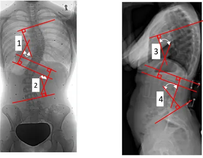
on December 2011 from: http://musclerad.blogspot.ca/2011/12/psoas-major- muscle.html. 11 Figure 1.9: Measurement of the 1) Thoraco- lumbar curve Cobb angle, 2) kyphosis and 3)
lordosis in a scoliotic subject (Saint- Justine University Hospital database) ... 13 Figure 1.10: Pelvic obliquity determined by contra- lateral ASIS in a subject thoracic deformity
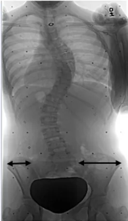
(Saint-Justine University Hospital database) ... 14 Figure 1.11: Pelvic rotation in the transverse plane presented as unequal ilium width on the
antero-posterior radiograph (Saint-Justine University Hospital database.) ... 15 Figure 1.12: The presentation of the spiral path in pelvic rotation: upper part rotates clockwise
while the pubic symphysis rotates counter clockwise (Boulay, 2006-a) ... 15 Figure 1.13: Sacroiliac parameters: pelvic tilt (PT), pelvic incidence (PI), sacral slope (SS) and
Figure 1.14: Spino-pelvic relative parameters in the sagittal balance used to describe postural equilibrium in subjects ... 19 Figure 1.15: a) Frontal and b) sagittal balance defined as the angle between line connecting the
T1 and L5 and vertical line in frontal and sagittal planes respectively. Viewed in Clindexia software (Sainte Justine University Hospital, Montreal) ... 20 Figure 1.16: Position of the center of the femoral head vertical axis, trunk inclination, and C7
plumb- line. Clindexia software (Saint-Justine University Hospital, Montreal)... 21 Figure 1.17: Kinematic analysis of the trunk-pelvic interaction by mean of motion capture
systems in AIS during a) trunk movement (Pasha, 2010) and b) gait (Mahaudens, 2009) .. 23 Figure 1.18: Force plate with four force transducer. (X,Y) determines the COP position, F is the
reaction force, and F1 to F4 determines the registered force at each
corner………...………...…..…26 Figure 1.19: a) 3D reconstruction of the spine, pelvis and ribcage b) The corresponding FE model of the anatomical sections (Aubin, 1996)………...………...33 Figure 1.20: Biomechanical model of the spine and pelvis (MD ADAMS, 2010)…………...…33 Figure 1.21. Hybrid model of the spine (Gharbi, 2008)... 34 Figure 1.22 : Compressive stress distribution on the superior sacrum endplate ( front (F) and
back (b)) in sponlylolisthesis subjects with different sacro-pelvic parameters (PI, SS, and slip percenage %) (Sevrain, 2012)……….……….……...….35 Figure 3.1: (A) Marker configuration on the torso and pelvis; (B) Identification of movement
onset and maximal range-of- motion (ROMmax). ... 54
Figure 3.2: Sacro-pelvic morphological parameters: pelvic tilt (PT), pelvic incidence (PI) and sacral slope (SS) ... 54 Figure 3.3: Pelvic alignment in the three planes (sagittal, frontal and transverse) for each
movement type at maximum range of motion. ... 55 Figure 3.4: Comparison between pelvic ROM (ROMpelvis) and total ROM (ROMmax). (A) Pelvic
contribution to total ROM for all movement types; (B) The interaction effect evident during left axial rotation. ... 56
Figure 3.5: Schematic illustrating the calculation of (A) pelvic frontal tilt (pelvicFTilt) in the
coronal plane and (B) pelvic axial rotation (pelvicRot ) in the transverse plane... 60
Figure 3.6: (A) Schematic representation of the possible pelvic orientation in the frontal and transverse planes (B) Illustration of the pseudo-sagittal projection of pelvic orientation in the frontal and transverse planes ... 61 Figure 3.7: Presentation of the pelvic orientation in (A) Right main thoracic (MT) (n=80) (B)
Left thoracolumbar/lumbar (TL/L) (n=80), and (C) Controls ( n=35). Angles are presented in degrees……….………...…63 Figure 3.8: A schematic illustrating the tendency of the spino-pelvic relative orientation in
transverse and coronal planes in (A) MT and (B) TL/L. The values are the percentage number of cases (n=80 in both groups) with the demonstrated pelvic orientation. ... 64 Figure 3.9: The effect of the reconstruction error on the pelvic orientation in the MT group…..66 Figure 4.1: Osseo- ligamentous finite element model of the trunk ... 85 Figure 4.2: Steps in computation of the stress distribution and the COPS1 position on the S1
endplate: a. Biplanar radiographs, b. 3D reconstruction of the spine and pelvis, c. Finite element simulation of the gravitational loads on the spine and pelvis, d. Compressive stress distribution on the S1 endplate (scaled between the minimum and maximum stress magnitude) and the position of the COPS1. ... 86
Figure 4.3: Distribution of the COPS1 position in the transverse plane in the three groups. ... 87
Figure 4.4: Distribution of the COM position in the transverse plane in the three groups ... 88 Figure 4.5: Cluster analysis of the stress distribution on the superior endplate of the sacrum in the
three groups of subjects. The dashed line depicts the center line of the sacrum in the local coordinate system of the sacrum. ... 89 Figure 4.6: The origin and the axis orientation of the coordinate system on the force plate (first
experimental setup). ... 92 Figure 4.7: a) The position of the calibration object on the pressure mat. b) The location of the
Figure 4.8: The correlation between the COM and the COP positions: a) in postero-anterior direction, b) in the medio- lateral direction. ... 98 Figure 4.9: a) Presentation of the bi-planar radiographs and the calibration object b) The 3D
position of the vertebrae and the center of mass of each vertebra slice after optimization in the sagittal plane and c) in the frontal plane. (0, 0) is the position of the mid point of the femoral heads…….………...………...…...99 Figure 4.10: Stress distribution on the superior plate of sacrum before and after optimization of the position of the center of mass ... 101 Figure 5.1: Biplanar radiographs and the location of the high and low stress areas on the sacrum
endplate before and after surgery in a typical a) Lenke 1 and b) Lenke5 subject. The dash line separates the anterior and posterior parts of the sacrum. ... 104
LIST OF SYMBOLS AND ABBREVIATIONS
2D Two dimensional
3D Tridimensional
AIS Adolescent idiopathic scoliosis ASIS Anterior- superior iliac spine C1-C7 Cervical vertebrae
CHVA Center of the hip vertical axis CNS Central nervous system COM Center of mass
COP Center of pressure
COPS1 Barycenter of the stress distribution on the S1 endplate
DLT Direct linear transformation FEM Finite element model
GL Gravity line
L1-L5 Lumbar vertebrae
mm millimetre
MT Main thoracic
ROM Range of motion
RT Right thoracic
RTLL Right thoracic with compensatory left lumbar curve PSIS Posterior-superior iliac spine
PI Pelvic incidence
PSIF Posterior spinal instrumentation and fusion
S1-S5 Sacral vertebrae SIJ Sacroiliac joint
SS Sacral slope
T1-T12 Thoracic vertebrae
INTRODUCTION
The human spine is a complex structure providing mobility and stability in different postures. In spinal deformities like scoliosis, the overall postural equilibrium and stability of the patients are affected (Chen, 1998; Nault, 2002; Beaulieu, 2009). The close interaction between the postural parameters and the stability in scoliosis makes the postural parameters analysis essential in the AIS evaluation.
The pathology of scoliosis includes but is not limited to the anatomical abnormalities of the spine; thoracic and lumbar deformities in sagittal and frontal planes (King, 1983; Lenke, 2001), vertebral rotation in the transverse plane (Stokes, 1986; Lam, 2008), rib cage distortion
(Grivas, 2006), pelvis asymmetry, rotation, and obliquity (Lucas, 2004; Gum, 2007), as well as alternations in the femoral heads position (Saji, 1995) have been reported in scoliosis cases. The relative orientation of the spine and pelvis in the sagittal plane is also affected in scoliosis and subsequently impacts the patient’s sagittal balance (Berthonnaud, 2005; Berthonna ud, 2009). Moreover, the postural deformities resulting from scoliosis impact the kinematic of the movement (Mahaudens, 2005, Skalli, 2006) and muscular energy consumption (Fe ipel, 2002; Mahaudens, 2008 ). Postural deformities in AIS not only cause poor self- image in patients (Lonstein, 2006) but also, from a biomechanical point of view, are coupled with impaired postural balance and inefficient stability (Chen, 1998; Dalleau, 2011) which subsequently interferes with the patient daily life. Different studies have tried to characterize scoliotic deformities via postural analysis of the patients. However these methods are mainly limited to the postural analysis of the patients in the sagittal plane in static standing position (Upasani, 2007; Berthonnaud, 2009) and fail to provide information about the overall three-dimensional spino-pelvic deformities in scoliosis. Furthermore despite many literatures on the geometrical postural analysis of the AIS in the sagittal plane there is not much known about the biomechanics of the 3D spino-pelvic interaction and the differences due to various scoliotic spinal curves.
Bearing in mind the importance of the spino-pelvic postural analysis in scoliosis, characterization of the spino-pelvic interaction and its biomechanics in scoliotic subgroups were of interest of this Ph.D. thesis. The 3D relationship between the spinal and pelvic deformities in static, the kinematic of the spine and pelvis, and the biomechanical loading of the sacrum due to
the altered orientation of the spine and pelvis were investigated in scoliotic subgroups. The impact of the surgical spinal correction on the sacral loading and the transferred load between the spine and pelvis was also examined. The role of the pelvis in scoliosis was studied more closely in static and dynamic and the relationship between the morphological and biomechanical parameters of the spine and pelvis in the AIS subgroups were highlighted.
In the present document, after reviewing the pertinent literatures, the unreciprocated questions in the scoliosis postural analysis are listed. The objectives of the project are separately analyzed in five sections, including two scientific articles and three additional studies. Finally, a general discussion and conclusion highlight the important results and the clinical significance o f the project.
Chapter 2: Objectives and hypothesis
Chapter 3: Pelvic 3D range of motion and trunk pelvic interaction in adolescnet idiopathic scoliosis (Article1)
Spinopelvic compensatory mechanisms in adolescent idiopathic scoliosis
Chapter 4: Finite element analysis of the biomechanical loading of the sacrum in adolesent idiopathic scoliosis (Article 2)
Effect of the position of the center of mass on sacral loadingEstimation of the 3D position of the center of mass in
numerical simulations of the scoliotic spine
Chapter 5: The biomechanical effects of the spinal surgery on the spino-pelvic parameters in adolescent idiopathic scoliosis
Chapter 1: Literature review
Chapter 6: General Discussion
CHAPTER 1
LITERATURE REVIEW
1.1 Descriptive
anatomy and functions of the normal trunk
1.1.1 Spine
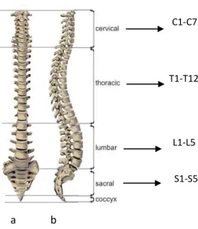
The human spine contains five sections: cervical (7 vertebrae), thoracic (12 vertebrae), lumbar (5 vertebrae), sacrum (5 fused vertebrae), and coccyx (4-5 fused vertebrae) (figure 1.1). The vertebral size is different in each spinal section. Lumbar vertebrae are larger in size in comparison to thoracic and cervical vertebrae which make them more appropriate to carry the whole trunk weight. In the posterior part of the vertebrae, the spinous processes of two succeeding vertebrae are connected via the interspinous and supraspinous ligaments. The posterior facet joints (zygapophyseal joints) connect the articular facets of adjacent vertebrae. In the anterior part, the vertebrae are bounded with two adjacent intervertebral disks. Each intervertebral disk and its two adjacent vertebrae provide the kinematic component of the spine namely the motion segment (figure1.2).
Intervertebral disks consist of the nucleus pulposus and the surrounding part namely annulus fibrosus. The ribcage is connected to the vertebral transverse processes and vertebral body, and contains 24 ribs, sternum, and costo-vertebral cartilaginous joints. The inferior part of the spine, the sacrum, is connected to the iliac bone on each side (Ellis, 2006). A detailed description of the pelvis is provided in the next section.
The spine normally appears as a straight line in the coronal plane. In the sagittal plane, the spine consists of 4 curves-two lordosis and two kyphosis curves: cervical lordosis, thoracic kyphosis, lumbar lordosis, and sacral kyphosis. In a normal spine, the curves magnitude vary by age and gender (Voutsinas, 1986; Fernand and Fox, 1985).
Groups of muscles provide flexion-extension (erector spinae, gluteus, and rectus abdominus), lateral bending, and axial rotation (erector spinae at ipsilateral side, rotatores and multifidus at the central- lateral side) of the spine. The co-contraction of these muscles provides spinal balance (White and Panjabi, 1990). Groups of spinal muscles connect different parts of the spine, as well as pelvis and lower extremities.
The motion of each vertebra is controlled by the synovial joints and pertinent muscles and ligaments. The translational and rotational motion of each vertebra is shown in figure 1.3. Each vertebra has six degrees of freedom. The range of motion (ROM) and the coupling mechanism of
a b
C1-C7
T1-T12
L1-L5
S1-S5
Figure 1.1: a) Frontal and b) sagittal views of the spine and its principal sections.
Figure 1.2: Vertebrae and inter vertebra disks, facet joints and pedicles (Right), Spinal motion segment (left). Consulted on January 10 2012 from: http://www.ucneurosurgery.com/spinal.html.
the spinal vertebrae in 3D vary in thoracic and lumbar sections. The thoracic spine has limited movement due to its connection to the ribcage; its ROM decreases from T1 to T6 and increases from T6 to T12 during trunk flexion-extension. During lateral bending its ROM increases gradually from T1 to T12. The most important motion of the thoracic vertebrae is the axial rotation which gradually decreases from T1 to T12. The maximum range of motion of the thoracic vertebrae is about 9 degrees in adults (White and Panjabi 1990). The range of motion of the lumbar spine vertebrae increases from L1 to L5 during flexion-extension while its ROM is almost constant throughout the lumbar section during axial rotation (White and Panjabi 1990).
A coupling mechanism between axial rotation and lateral bending is observed in the thoracic and lumbar spine during trunk movement. The coupling mechanism is different in thoracic and lumbar sections (Harrison, 1999). While the axial rotation of the spinal vertebrae is in the direction of its lateral bending in the lumbar spine, the thoracic vertebrae rotate in the opposite direction of the lateral bending in the thoracic spine.
1.1.2 Pelvis
The pelvic bony structure or pelvic girdle is one of the massive bony structures in the human body. The pelvis consists of 4 notable sections that form pelvic wall: 2 hip bones (ilium) (anterior and lateral parts), sacrum (posterior part), and pubic, and ischium (inferior part) (figure
X Y
Z
Figure 1.3: Six degrees of freedom of a functional unit (translations and rotations), White and Panjabi 1990.
1.4). Iliums are fused at the pubic symphysis and create the pubic arch. In the skeletal classification sacrum is considered as an axial skeleton similar to what is found in the skull, vertebrae, and thoracic cage. On the other hand, ilium is considered as a part of the appendicular skeleton similar to the lower and upper extremities bones and shoulder girdle (scapulas and clavicle). This skeletal classification is based on the role of the bony structure; while the axial bones are built to protect the sensitive members like brain and spinal cord, the appendicular bones are more involved in the movement (Gray 1918; Netter, 2010). The hybrid structure of the pelvis demonstrates both functions of the pelvic structure. While appendicular skeleton transfer the movement from the lower extremity via iliums and sacrum to the spine (axial skeleton) the axial skeleton has a protective role during pregnancy (Netter, 2010).
Three diametrical measurements, diagonally (oblique) (1), postero-anterior (2), and medio- lateral (3), are used to define the size of the pelvic cavity from the superior view (Gray, 1918). From the inferior view two diameters, postero- anterior (4) and medio- lateral (5) are used Figure 1.4: Pelvic bones: 1) Ilium 2) Sacrum 3) Sacroiliac joint 5) Coccyx 6) Pubis 7) Ischium 8) Pubic symphysis 9) Femoral/hip joint (Grey’s anatomy 20th
edition).
Ilium Sacrum Sacro iliac joint
Ischium Pubic symphysis
Femoral/hip joint Pubis
to measure the pelvic cavity (figure 1.5). While these measurements are symmetrical in control subjects, in the scoliotic pelvis unequal radii in the pelvic cavity are reported (Boulay, 2006).
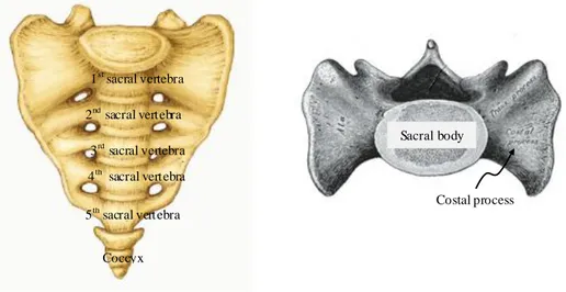
1.1.3 Anatomy of the sacrum
Sacrum is a part of both spine and pelvis. More specifically, it contains of 5 fused vertebrae (figure 1.6). The sacrum movement with respect to the coccyx and between the sacrum bones is limited as a result of the specific shape and its restricted connection. Sacroiliac and iliolumbar ligaments keep the sacrum in its place. Consequently the main movement of the sacrum originates from the laxity and stretching of this group of ligaments (Gray, 1918).
1 2 3
5 4
Figure 1.5: Pelvic diameters from top view: 1- Diagonally, 2- antero-posterior, 3- medio-lateral and from inferior view 4- antero-posterior, 5- medio- lateral (Grey’s anatomy 20th edition).
Figure 1.6: The sacrum anterior and top views (Gray’s anatomy 20th edition), Consulted on January 2012 from http://www.bartleby.com/107/24.html.
1st sacral vertebra 2nd sacral vertebra 3rd sacral vertebra 4th sacral vertebra 5th sacral vertebra Coccyx Sacral body Costal process
1.1.4 Anatomy of the sacroiliac joint (SIJ)
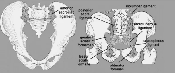
The SIJ connects the ilium bones and sacrum in the posterior part of the pelvic r ing. This joint is an amphiarthrodial joint, covered with cartilages. The SIJ is considered as two joints that connect the left and right sides of the sacrum to the left and right iliums respectively. The sacrum surface connects to the ilium via ligaments. This group of ligaments is divided in three parts based on their articulated section on the sacrum (Ellis, 2006) (figure 1.7). A detail description of this group of ligaments is presented shortly.
1.1.5 Sacroiliac joint function
The SIJ main function is the shock absorption between the pelvis and adjacent parts (Wilder, 1980; Lavignolle, 1983). The movement of this joint is limited and involves separation and elongation of the connecting ligaments (Wilder, 1980).
Another function of the SIJ is absorbing the shear force during gait (Wilder, 1980). The accelerating movement of the trunk and legs decelerates as the heel strike occurs. The changes in the movement acceleration cause a shear force at the SIJ which damps with SIJ ligaments (Wilder, 1980).
Figure 1.7: Anterior and posterior view of the pelvic ligaments. Consulted on August 2011 from: http://home.comcast.net/~wnor/pelvis.htm.
http://home.comcast.ne/pelvis.htm
1.1.6 Sacroiliac joint ligaments
Sacroiliac ligaments guarantee the position of the sacrum with respect to the ilium. The range of motion of the sacrum is restrictedly dictated by these ligaments. The elongation of these ligaments makes the sacral motion possible. Sacrum is considered as a part of the spine as was explained in the section 1.1.1. Sacrum is also considered as a part of the pelvis (Gray, 1918) however its connection to the rest of the pelvis is ligamentous.
Three groups of ligaments connect different parts of the sacrum to the pelvis. This classification is based on the location of the origin point or direction of these ligaments on the sacrum.
a) Anterior sacroiliac ligament
Sacral anterior ligaments connect sacrum to ilium. Anterior sacroiliac ligament, iliolumbar ligament, and lumbosacral ligament connect to the sacrum and ilium superiorly. The sacrotuberous and sacrospinous connect the inferior part of the sacrum to the ilium (Gray, 1918).
b) Posterior sacroiliac ligament
Due to the specific shape of the sacrum and the load transmission between sacrum and ilium, the posterior ligaments are the most important group of ligaments in the sacrum- ilium junction. These ligaments are divided in two groups: 1. Lower part liga ments (long posterior sacroiliac ligament) which are aligned obliquely and attach the back of the lower part of the sacrum (third transverse tubercles) to the posterior superior part of the ilium, 2. The upper part ligaments (short posterior sacroiliac ligaments) which are aligned horizontally and attach the upper part of the sacrum (first and second transverse tubercles) posteriorly to the ilium (Gray, 1918).
c) Interosseous ligaments
This group of ligaments is deeply located at the posterior part of the sacrum and keeps the sacrum and ilium together (Gray, 1918).
Beside these three groups of ligaments, two more groups are linked between sacrum’s parts or ilium sections only. Anterior longitudinal ligaments connect s acrum sections vertically. The Inguinal ligament connects the lower part of the ilium wing to the pubic bone anteriorly.
1.1.7 Pelvic muscles
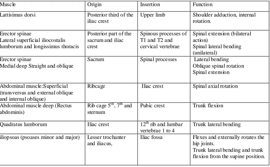
Multiple pelvic muscles originate from various parts of the spine, pelvis, and lower extremities. Pelvic muscles originate from the pelvic ilium to lumbar spine (quadratus lumborom), thoracic spine (longissimus dorsi), the ribcage (iliocostalis lumborum), and inferiorly to the femur. Tables 1.1.and 1.2 summarize the origin- insertion and functionality of the muscle groups between the pelvis and lower e xtremities (Table1.1) and between spine and pelvis (Table1.2) (Ellis, 2006). Figure 1.8 depicts this group of muscles.
Table 1.1 : Muscles originating from the pelvis and inserting in the lower extremities
Muscle Origin Insertion Function
Internal and Extensor obturator
Obturator foramen Trochanteric fossa Hip external rotation Quadratus femoris Ischial tuberosity Intertrochanteric
crest
Hip external rotation , thigh and hip adduction Superior and
inferior gemelli
Ischial spine and ischial tuberosity (respectively)
Greater trochanter Assist internal obturator
Figure 1.8: The anterior view of the Psoas and Illiacus muscles position. Consulted o n December 2011 from: http://musclerad.blogspot.ca/2011/12/psoas- major-muscle.html.
Psoas major Illiacus
Femur
Pelvis Spine
Table 1.2: Muscles connecting the pelvis to trunk
Muscle Origin Insertion Function
Lattisimus dorsi Posterior third of the iliac crest
Upper limb Shoulder adduction, internal rotation.
Erector spinae
Lateral superficial iliocostalis lumborum and longissimus thoracis
Posterior part of the sacrum and iliac crest
Spinous processes of T1 and T2 and cervical vertebrae
Spinal extension (bilateral action)
Spinal lateral bending (unilateral)
Erector spinae
Medial deep Straight and oblique
Sacrum Spinal processes Lateral bending Oblique spinal rotation Spinal extension
Abdominal muscle:Superficial (transversus and external oblique and internal oblique)
Ribcage Iliac crest Spinal axial rotation
Abdominal muscle deep (Rectus abdominis)
Rib cage 5th, 7th and sternum
Pubic crest Trunk flexion
Quadratus lumborum Iliac crest 12th rib and lumbar vertebrae 1 to 4
Trunk lateral bending iliopsoas (psoases minor and major) Lesser trochanter
and iliacus,
Iliac fossa Flexes and externally rotates the hip joints.
Trunk lateral bending and trunk flexion from the supine position.
1
2
4 3
1.2 Scoliotic spine and pelvis
The morphology of the spine and pelvis is subject to changes during the scoliotic progression. Various parameters and measurements are conventionally used in clinics to evaluate the scoliotic deformities in patients.
1.2.1 Scoliotic spine deformities
Spinal deformities in scoliosis appear in coronal, axial, and sagittal planes. The magnitude of the scoliotic curves in the coronal plane is calculated by the Cobb’s angle, which represents the angle between the lines perpendicular to transitional vertebrae endplate of each curve (figure 1.9). The analytical Cobb angle is an alternate measurement and is defined by the lines perpendicular to the spinal curve at the location of its inflection points. Thoracic kyphosis and lumbar lordosis are measured in the sagittal plane. Vertebral rotation in the transverse plane and vertebral deformation (wedging) are also reported in scoliosis (Stokes, 2001).
Scoliotic spinal deformities can occur in one or many of the spinal sections including the cervical, proximal thoracic, main thoracic, thoraco- lumbar, lumbar and/or lumbo-sacral curves. Cervical and lumbar lordosis and thoracic and sacral kyphosis which are measured in the sagittal plane are also subject to change during the progression of scoliosis.
Figure 1.9: Traditional method in measurement of the 1) Thoraco- lumbar curve Cobb’s angle, 2) kyphosis and 3) lordosis in a scoliotic subject (Saint- Justine University Hospital database).
The degree of the thoracic and lumbar spines rotation was explained in Stagnara’s “Plan d’élection” (1985). A view of the spine in the transverse plane was developed to measure the orientation of the plane of maximum curvature in the scoliotic spine ( Labelle, 2011).
1.2.2 Pelvic parameters in scoliosis
Scoliosis is associated with changes in the pelvic morphology and orientation (Boulay, 2006-a; Gum, 2007). Boulay (2006-a) measured unequal pelvic antero-posterior and medio-lateral diameters (figure 1.5). The position of the pubic bone, acetabulum, ischium, and the iliac crest width were measured on the radiographic images (Boulay, 2006-a; Gum, 2007). Unequal contra- lateral iliac crest wing width suggested a transversal rotation of the pelvis along with a torsion/ deformation of the pelvis in subjects. Gum (2007) showed that the pelvis is rotated in the direction of the major curve in the transverse plane. Also pelvic tilt in the frontal plane (pelvic obliquity) is reported in scoliotic subjects (figure 1.10) (Nault, 2002; Zabjek, 2005; Skalli, 2006).
3D measurement of the pelvic parameters showed that sacrum, iliac blade, iliac width, acetabulum, and the superior surface of the acetabulum are asymmetric in scoliosis (Boulay, 2006-a) (Figure 1.11). Also pelvic torsion was reported in this group of subjects: The upper part, measured from anterior and posterior contra- lateral iliac markers, rotates clockwise while the Figure 1.10: Severe pelvic obliquity determined by contra- lateral ASIS position in a subject with thoracic deformity (Saint-Justine University Hospital database).
pubic section rotated counter clockwise which consequently causes torsion in the pelvic body (Boulay, 2006-a) in non-scoliotic subjects (figure 1.12). It was suggested that pelvic rotation is more pronounced in scoliotic subjects and can be evaluated clinically by measuring the ASIS and PSIS orientation (Boulay, 2006-a). Similar results were reposted in scoliotic subject with right thoracic deformity (Stydianides, 2012). The asymmetric iliac wing length was only significantly different in subjects with sever scoliotic deformities (Stydianides, 2012). However a recent study did not measure any asymmetry in the pelvic structure in scoliotic group and suggested that asymmetrical concave and convex sides iliac that appears on the antero-posterior radiographs are only due to the pelvic transverse rotation (Qiu, 2012)
Figure 1.11: Pelvic rotation in the transverse plane presented as unequal ilium width on the antero-posterior radiograph (Saint-Justine University Hospital database).
Figure 1.12: The presentation of the spiral path in pelvic rotation: upper part rotates clockwise while the pubic symphysis rotates counter clockwise (Bo ulay, 2006-a).
Furthermore sagittal pelvic parameters are defined by the relative alignment and orientation of the sacrum and femoral heads. Sacral slope (SS), pelvic incidence (PI), and pelvic tilt (PT) are the most widely used parameters in evaluation of the sagittal pelvic alignment in scoliotic and spondylolisthesis subjects. The relationship between these parameters and the sagittal profile of the spine is also investigated in pre- and post operative subjects.
More precisely, the SS is defined as the angle between the horizontal line and line parallel to the sacral endplate. PI is the angle between the line connecting the center of the femoral head to the center of the sacral endplate and the line perpendicular to the sacral endplate. Finally, PT is measured as the angle between the line connecting the center of the femoral head to the center of the sacral endplate and the vertical line. Equation 1.1 relates these three parameters. Furthermore pelvic overhang is used to measure the distance between the femoral head and the midpoint of sacrum in the sagittal plane (Labelle, 2005) (figure 1.13).
Equation1.1
Figure 1.13: Sacro- iliac parameters: pelvic tilt (PT), pelvic incidence (PI), sacral slope (SS) and pelvic overhang.