HAL Id: hal-00513670
https://hal.archives-ouvertes.fr/hal-00513670
Submitted on 1 Sep 2010HAL is a multi-disciplinary open access
archive for the deposit and dissemination of sci-entific research documents, whether they are pub-lished or not. The documents may come from teaching and research institutions in France or abroad, or from public or private research centers.
L’archive ouverte pluridisciplinaire HAL, est destinée au dépôt et à la diffusion de documents scientifiques de niveau recherche, publiés ou non, émanant des établissements d’enseignement et de recherche français ou étrangers, des laboratoires publics ou privés.
To cite this version:
Eric Felder. Analytical correlation of indentation experiments. Philosophical Magazine, Taylor & Francis, 2006, 86 (33-35), pp.5239-5250. �10.1080/14786430600627285�. �hal-00513670�
For Peer Review Only
Analytical correlation of indentation experiments
Journal: Philosophical Magazine & Philosophical Magazine Letters Manuscript ID: TPHM-05-Nov-0488.R1
Journal Selection: Philosophical Magazine Date Submitted by the
Author: 06-Jan-2006
Complete List of Authors: Felder, Eric; Ecole des Mines de Paris Keywords: modelling, contact mechanics, indentation Keywords (user supplied):
For Peer Review Only
Analytical correlation of indentation experiments
E. Felder
Centre de Mise en Forme des Matériaux (CEMEF), UMR 7635 CNRS-Ecole des Mines de Paris BP 207 F 06904 Sophia-Antipolis France1
ABSTRACT
We improve the analysis of indentation by the model of the expansion of a spherical cavity by considering a generalisation of the velocity field proposed by Avitzur for metal extrusion: its components vary with the distance to the indenter apex r as 1/rs with s a free parameter. By neglecting the material displacement we apply this model to conical indentation (apical angle 2θ) of an elastic solid (Young’s modulus E), a rigid perfectly plastic (RPP) solid (yield stress σ0) and elastic perfectly plastic (EPP) solids with indentation index X
= (E*/σ0)cotθ and estimate the hardness H and the shape ratio c = hc/h where h and hc are the
penetration depth and the contact depth. s is determined by minimising the total work (elastic case) and the plastic power (RPP and EPP cases). The results of the model are in agreement with the available exact results (elastic case) and numerical ones (RPP and EPP cases).
§ 1. INTRODUCTION
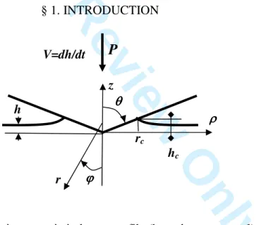
Figure 1. Axisymmetric indenter profile (here the cone p = 1).
We consider the indentation of an homogeneous solid by an axisymmetric indenter with a power law profile (figure 1):
1 1 ) ( = − → = p− p c c p p pR r h pR z h ρ (1)
rc is the contact radius and hc the contact depth. The sphere (radius R) corresponds to p = 2;
the flat punch corresponds to p ∞ and a constant contact radius rc. The cone with the apical
1
Tél. : (33) (0)4 93 95 74 28 Fax : (33) (0)4 92 38 97 52 E.Mail : [email protected] ρρρρ
P
rc z hc h θθθθ r ϕϕϕϕ V=dh/dt 2 3 4 5 6 7 8 9 10 11 12 13 14 15 16 17 18 19 20 21 22 23 24 25 26 27 28 29 30 31 32 33 34 35 36 37 38 39 40 41 42 43 44 45 46 47 48 49 50 51 52 53 54 55 56 57 58 59 60For Peer Review Only
angle 2θ corresponds to p = 1 and Rp-1 = tanθ. The mechanical analysis of indentation provides two very important quantities for the instrumented indentation [1]:
the shape ratio
h h cp = c
the reduced hardness
0
*
σ H
H = (2)
The shape ratio cp provides the contact depth hc (figure 1) starting from the indentation depth
h, and so the projected contact area A and the hardness H = P/A, the reduced hardness H* provides the link between the hardness and the flow stress σ0 of the material.
A complete description of the indentation of elastic solids (Young’s modulus E,
Poisson’s ratio υ) is available [2]. The conical indentation of rigid-perfectly plastic (RPP) solids has been analysed by the slip line field (SLF) method [3]. For elastic-perfectly plastic (EPP) solids Johnson [4] provides the matter balance in the model of the expansion of a spherical cavity proposed by Hill and so predicts that H* is a linear function of the logarithm of the indentation index:
β σ tan * 0 E X = (3)
E* is the effective elastic modulus [1,2] (for rigid indenter E* = E/[1-υ2]); β is the angle of inclination of the indenter at the edge of the contact; for a cone β= π/2-θ, for a sphere tanβ = rc/R. But according to this model whose velocity field is purely radial, the sample surface
remains plane (the shape factor cp = 1), H* increases steadily with X and the representative strain and strain rate have not been derived. Besides this analytical analysis, Ramond-Angélélis [5] has analyzed by the finite element method the conical indentation of EPP solids for θ = 70.3 deg and Tresca friction coefficient m= 0 and 1 (m is the ratio between the friction shear stress and the solid maximal shear stress); her results are in good agreement with elastic and SLF analysis [6].
Our aim is to improve the model of the expanding cavity in order to provide an analytical approach to the conical indentation. It is based on a velocity field which depends on a free parameter s which describes the evolution of the velocity with the radial distance r to the cone tip (figure 1). By assuming tanβ << 1 for which we can neglect the material displacement, we use the upper bound theorems and estimate the value of s by minimising the work (elastic solid) or plastic power (EPP solids) and estimate cp and H*.
§ 2. KINEMATIC AND GEOMETRICAL ASPECTS 2.1. The velocity field
We consider the velocity field in spherical coordinates (r,ϕ,ψ) (figure 1)
u ( ) 0 sin 2 2 cos c s c s c r r r dt dh V with u r r s V u r r V u > = = − = = ψ ϕ ϕ ϕ (4) 3 4 5 6 7 8 9 10 11 12 13 14 15 16 17 18 19 20 21 22 23 24 25 26 27 28 29 30 31 32 33 34 35 36 37 38 39 40 41 42 43 44 45 46 47 48 49 50 51 52 53 54 55 56 57 58 59 60
For Peer Review Only
For s = 1, it is the velocity field induced in an elastic half space by a concentrated normal force at r = 0 [2]. For s = 2, it is the radial field proposed by Avitzur for describing axisymmetric metal extrusion or drawing [7]. It is incompressible and induces a velocity discontinuity at r = rc with a dead zone below the indenter (where we assume u = V); we do
not take into account this discontinuity further. The decrease rate of the matter velocity with the distance to the indenter depends on the value of the exponent s. So we can obtain the various possible cases:
• sink-in for s < 2 (uϕ(r,π/2) < 0)
• pile-up for s > 2 (uϕ(r,π/2) > 0).
By neglecting the material displacement (asymptotic model valid if tanβ << 1 and/or high friction [8]), it is possible to derive the value of the shape ratio cp which takes the following form for the present velocity field:
∫
− + − + = c r c c p s c c p r t dr r t r s p c 0 1 ) ( ) ( 2 2 1 (5)rc(t) is the current value of the contact radius and rc its final value. For the limiting cases
(elastic and RPP solids), s does not depend on rc(t) and the shape ratio is related simply to the
values of s and p: + + = s p p s cp 2 2 (6)
For conical indenter, geometrical similarity insures that the shape ratio c and the reduced hardness H* are in all cases constant. In the EPP case the ratio B = b/rc of the elastic-plastic
boundary radius b to the contact radius rc is constant and in each zone we describe the
velocity field by a constant value of s. So for conical indentation of EPP solids, the calculation of (5) must be performed with a value se = 1 for rc(t) < rc/B (elastic zone, see
§ 3.1) and another value of s for rc/B < rc(t) < rc(elastoplastic zone):
+ − + = +1 2 1 ) 1 ( 2 3 s B s s s c (7)
2.2. The strain rate field and the strain level
Application of the standard formula [9] provides easily the non zero strain rates:
(
)
− = = = − = + + + ϕ ε ϕ ε ε ϕ ε ϕ ψ ϕ sin 4 1 cos 2 cos 1 1 1 s c c r s c c s c c r r r r V s s r r r V s r r r V s & & & & (8)So the second invariant of the strain rate field is: 2 3 4 5 6 7 8 9 10 11 12 13 14 15 16 17 18 19 20 21 22 23 24 25 26 27 28 29 30 31 32 33 34 35 36 37 38 39 40 41 42 43 44 45 46 47 48 49 50 51 52 53 54 55 56 57 58 59 60
For Peer Review Only
(
)
− + = + ϕ ϕ ε ε 2 2 2 2 1 sin 12 1 cos 2 3 s r r r V s s c c ij ij& & (8)For the case where s is constant and uniform, we can estimate the generalised strain [9]:
(
)
1 12 1 1 1 ln 1 1 2 1 ) ( tan 2 ) ( 2 sin 3 2 sin ) ( 2 1 0 2 / 0 0 2 / 0 < − = + − − + = + = = = +∫ ∫
∫ ∫
s S with S S S S s F where r r p s F dt d dt d r s c t ij ij t β ϕ ϕ ε ε ϕ ϕ εε π & π & &
(9)
F(s) is a slowly increasing function of s with F(1) = 0.5 and F(4.46) ~ 1; the time integration is in fact an integration versus h which is transformed in an integration versus rc(t) by using
(6), (2) and (1). We observe that as r increases the strain decreases very strongly if s ~ 4 (RPP case, see § 3.2). The equation (9) is in good agreement with empirical estimations of the representative strain for hardness of metals measured with cones [11] and spheres [10]: the strain increases in direct relation with tanβ and for s ~ 4 (plastic case) its maximal value (at r = rc) is about 2.2-2.5 times higher than the representative strains: 0.2rc/R or 0.3cotθ.
§ 3. THE LIMITING CASES 3.1. Indentation of an elastic material
First we consider the flat punch. Because the contact radius rc is constant, the strain
field εεεε is given by (8) in which we change V into h. The deviatoric stress tensor is s = 2µεεεε where µ = E/[2(1+υ)] is the elastic shear modulus. Because the velocity field is incompressible, the indentation work is (s > 1/2):
( )
(
)
(
)
− + − = =∫ ∫
∞ 6 1 1 1 2 sin 2 2 2 2 2 2 / 0 s s s h µr dr r d µ s W c r ij ij e c π ϕ ϕ ε ε π π (10)Because the displacement field solution minimises the work, the best estimation of s is obtained by minimising We with respect to s: this gives easily s = se= 1: the strain field of the
concentrated normal force is so recovered. So we can derive the force and its variation with h:
(
)
(
)
(
)
2 1 * 2 * 2 2 ν π δ δ δ π − = = = = ∂ ∂ = with r E dh dP h r E h r µ h W P c c c e (11)The difference with the exact result [2] is the factor δ ~ 1.09 for υ = 0.3; so the error is 9 % about. The general case (p finite) is obtained by assuming s = 1 and by integrating dP/dh and the strain field versus h [12], approach which is valid for zero friction and adhesion. As h is proportional to p c r (relations (1)-(2)), we obtain: 3 4 5 6 7 8 9 10 11 12 13 14 15 16 17 18 19 20 21 22 23 24 25 26 27 28 29 30 31 32 33 34 35 36 37 38 39 40 41 42 43 44 45 46 47 48 49 50 51 52 53 54 55 56 57 58 59 60
For Peer Review Only
h r E p p t dr R c t r t r E t dh t r E P p p c c p c r c h c c * 2 1 ) ( ) ( ) ( * 2 ) ( ) ( * 2 1 1 0 0 + = = = − −∫
∫
δ δ δ (12)The von Mises yield criterion sijsij = 4µ2εijεij is maximal at (r = rc,ϕ = 0) and yield occurs as it
attains 2σ02/3[9] for the value of the indentation index X0 and the mean contact pressure H0:
+ = = 2 1 1 tan * 0 0 p E X δ β σ and 3 2 0 2 0 0 0 σ π = = c r P H (13)
Comparison of the results of the present model with the exact results (table 1) demonstrates that the shape ratio is overestimated and the contact pressure underestimated. Such a discrepancy is expected because the exact solution is much more complex, but it is not very important because our aim is to study the EPP indentation. Yield occurs for the same pressure than for the classical expanding cavity model [4].
Table 1. Indentation of an elastic solid: Comparison of the exact results [2] with the results of the present model (υ = 0.3).
p 1 (cone ; tanβ = cotθ) 2 (sphere ; tanβ = rc/R)
c H/(E*tanβ) c2 H/(E*tanβ) X0 H0/σ0
Exact
results 2/π ~0.63 0.5 0.5 (4/3π) ~ 0.42 ~ 2.6 ~ 1.1 Model (s = 1) 0.75 0.467 0.66 0.35 1.8 0.66
3.2. Indentation of a RPP solid The plastic power [9] is (by assuming s > 2):
( )
− = =∫ ∫
∞ 2 ) ( 2 sin 2 0 2 2 2 / 0 0 s s sF r V dr r d s W c r p c σ π ϕ ϕ ε σ π π & & (14)The velocity field solution minimises the power [9]; so the best estimation is obtained by minimising the power with respect to s; this gives s = sp ~ 4.35 and the hardness
) /( r2V W
H = &p π c ~ 3.62σ0. These results apply to all indenter shapes. Such a value of the
exponent s corresponds to a quasi-radial distribution of strain rate and strain (see equation (8)) as observed in indentation of workhardened metals [4]. We see on table 2 that the present model provides values of the shape ratio and the hardness very near the values obtained with the asymptotic approach under sticking friction.
Table 2. Indentation of a RPP solid: Comparison of the results of the asymptotic analysis [8] and the results of the present model.
p 1 (cone) 2 (sphere) c c2 H*=H/σ0 Zero friction 1.263 1.44 3.05 Sticking friction 1.209 1.334 3.21 Model (s = 4.35) 1.219 1.37 3.62 2 3 4 5 6 7 8 9 10 11 12 13 14 15 16 17 18 19 20 21 22 23 24 25 26 27 28 29 30 31 32 33 34 35 36 37 38 39 40 41 42 43 44 45 46 47 48 49 50 51 52 53 54 55 56 57 58 59 60
For Peer Review Only
§ 4. INDENTATION OF EPP SOLIDS4.1. The velocity field
In the plastic zone (rc < r < b), the velocity field is given by (4) with an exponent s.
According to the results of §3.1 we assume that the elastic zone imposes at the elastic-plastic boundary a radial stress σrr(r = b)=-2σ0/3. In the elastic zone (r > b = Brc), the velocity field
has an exponent s = se = 1. Because the normal velocity must be continuous for r = b, the
velocity field is:
b r u r b b r V u r b b r V u s c s c r > = − = = 0 sin 2 cos ψ ϕ ϕ ϕ (15)
The value of b is obtained by writing that the yield criterion attains its critical value at r = b (and ϕ = 0) as the contact radius rc(t) is equal to the present value rc. So we obtain for all
indenter shapes, with B(t) the current value of B and t0 the time for which yield occurs:
2 2 0 1 0 1 2 * 1 ) ( ) ( ) ( * 1 ) ( ) ( ) ( 1 0 0 c t t c s t t c s r B E t dh t r t B E t dh t r t B b σ δ σ δ → = =
∫
∫
− − (16)Resolution is easy only for the flat punch (rc constant) or the cone. For the cone, c, s and B are
constant and t0 = 0; so we obtain easily the value of B versus the indentation index:
s s c X B or B c E X + + = = = 1 1 1 0 2 2 cot * δ δ θ σ (17)
The corresponding shape ratio c is given by (7).
4.2. Evolution of the velocity field and the hardness with the plastic zone radius The exponent s in the plastic zone is obtained by minimising the effective power [9]:
( )
∫
∫
−∫
( )
= b r r rr p c d b u b dr r d B s W 2 / 0 2 2 2 / 0 0 sin 2 , sin 2 , π π ϕ ϕ ϕ σ π ϕ ϕ ε σ π & & (18) So we obtain:( )
(
)
( )
= + ≠ − + − = − − 2 3 2 ln 2 4 2 3 2 ) ( 1 2 2 , 0 2 2 2 0 2 s if B F r V s if B s F B s s r V B s W c s s c p σ π σ π & (19) 3 4 5 6 7 8 9 10 11 12 13 14 15 16 17 18 19 20 21 22 23 24 25 26 27 28 29 30 31 32 33 34 35 36 37 38 39 40 41 42 43 44 45 46 47 48 49 50 51 52 53 54 55 56 57 58 59 60For Peer Review Only
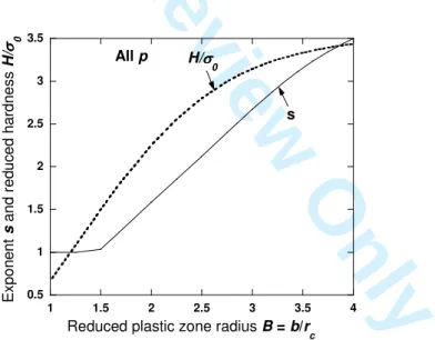
The hardness can be estimated as:H =W&p/(πrc2V) by using the calculated value of s. Such results apply to all indenter shapes. Numerical calculations reveal three domains of variation of s and H with B (figure 2):
• For 1 < B ≤ 1.5, the power increases steadily with s for s ≥ 1: so we assume s = 1. This domain corresponds to a progressive extension of the plastic zone starting from the initial yielding at a point. Integration of (16) is possible for all indenter shapes. X increases by a factor 2.25 and the indentation hardness increases almost linearly with X as in the elastic regime according to the equations:
≤ = + ≤ + = ≤ − = → ≤ ≤ punch flat B X finite p p B p X B H B δ δ δ δ σ σ 25 . 2 2 1 25 . 2 2 1 1 5 . 1 1 3 5 5 . 1 1 2 2 0 0 (20)
• For 1.5 ≤ B ≤ 3.5, the power has a minimum for a value of s which increases almost linearly with B from 1 to 3.11. So H increases with B in a parabolic manner from 1.5 to 3.32 σ0, a value 10 % lower than the value of the RPP case (§ 3.2).
• For B > 3.5, a minimum exists. H increases slower and tends toward the RPP value whereas the increase in s continues before becoming very slow: values very near the limiting value 4.35 of the RPP solids are attained for values of the indentation index very much higher than the values related to real materials; so this range is not included on figure 2. 0.5 1 1.5 2 2.5 3 3.5 1 1.5 2 2.5 3 3.5 4
Reduced plastic zone radius B = b/r
c H/σσσσ 0 s All p E x p o n e n t s a n d r e d u c e d h a rd n e s s H / σσσσ 0
Figure 2. Evolution of the reduced hardness H/σ0 and the plastic velocity field exponent s
versus the reduced radius of the plastic zone B = b/rc (all indenter shapes).
The expanding phase of the plastic zone has no mathematical limit; so we consider only the practical conditions which correspond to B < 4. The evolution of s with B can be described by a second order polynomial regression:
2 09262 . 0 5235 . 1 073 . 1 4 5 . 1 ≤B≤ s≈− + B− B (21) 2 3 4 5 6 7 8 9 10 11 12 13 14 15 16 17 18 19 20 21 22 23 24 25 26 27 28 29 30 31 32 33 34 35 36 37 38 39 40 41 42 43 44 45 46 47 48 49 50 51 52 53 54 55 56 57 58 59 60
For Peer Review Only
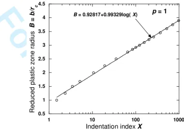
4.3. Application to conical indentationIn conclusion, the analysis is now complete: for a given value of B, equations (20) or (21) provide s; then (7) gives c; (17) furnishes X and finally (19) gives H*. We see on figure 3 that in first approximation the reduced plastic zone radius increases linearly with the logarithm of the indentation index, so at a rate which is significantly lower than the rate predicted by the classical cavity expansion model B ~ (X/3)1/3 [4]:
1000 5 . 1 ) log( 99329 . 0 92817 . 0 + ≤ ≤ ≈ X X B (22)
Figure 3. Evolution of the reduced radius of the plastic zone B = b/rc versus the
indentation index X for conical indentation (p = 1).
On the figure 4 are reported the evolutions of c and H* versus X according to the present model and the finite element calculations of Ramond-Angélélis [5] related to the cone with θ = 70.3 deg, equivalent to the Vickers and Berkovich pyramids. These calculations have been performed for zero friction or the maximal friction shear stress: these conditions correspond respectively to the values of Tresca’s friction coefficient m= 0 and 1; according to von Mises yield criterion the friction shear stress τ is given by the relation [9]:
1 0 3 0 ≤ ≤ =mσ m τ (23)
From the figure 4 we can draw the following conclusions:
- The shape factor is first overestimated for low values of X, because the elastic contact geometry is not very well described (see table 1); then it tends for high values of X as expected toward the values related to the indentation performed under maximal friction. - For X < 100 the hardness is very near the value related to maximal friction, and this
corresponds to a significant improvement with respect to the Johnson’s cavity model [4]. But after it becomes too high because in the RPP limit the hardness is overestimated with a difference of 12.7 % (see table 2).
We must notice that this comparison is not very easy because we do not know the values of c for 1 < X < 5. In addition it would be interesting to know the results related to higher values of θ for which the validity of the assumption of negligible displacements is better. Nevertheless the model is able to describe continuously the transition from the elastic case toward the RPP case. In addition it is in agreement with the major qualitative result of the finite element
0.5 1 1.5 2 2.5 3 3.5 4 4.5 1 10 100 1000 R e d u c e d p la s ti c z o n e r a d iu s B = b /r c Indentation index X B = 0.92817+0.99329log( X) p = 1 3 4 5 6 7 8 9 10 11 12 13 14 15 16 17 18 19 20 21 22 23 24 25 26 27 28 29 30 31 32 33 34 35 36 37 38 39 40 41 42 43 44 45 46 47 48 49 50 51 52 53 54 55 56 57 58 59 60
For Peer Review Only
calculations: the very large range of values of the indentation index X over which elasticity has a significant influence on the contact geometry.
a) Evolution of the shape ratio c versus the indentation index X.
b) Evolution of reduced hardness H/σ0 versus the indentation index X.
Figure 4. Comparison of the results of the present model with the results of the Johnson’s cavity model [4] and the results of the numerical simulation of conical indentation (θ =
70.3 deg) with the finite element method under zero friction (m = 0) and the maximal shear stress (m = 1) [5].
§ 5. CONCLUSION
In this paper we improve the model of the expansion of the spherical cavity by building a velocity field whose components vary with the distance to the indenter apex r as 1/rs with s a free parameter. By neglecting the material displacement and applying the upper bound theorems we calculate the more representative value of the free parameter s for elastic solid (s = 1) and RPP solid (s = 4.35). We analyse then the conical indentation of EPP solids characterised by the indentation index X and estimate the hardness H and the shape ratio c. The results of the model are in rather good agreement with the available exact results (elastic case) and the numerical ones (RPP and EPP cases). We obtain so a complete description from
0.6 0.7 0.8 0.9 1 1.1 1.2 1.3 1 10 100 1000 S h a p e r a ti o c Indentation index X m = 0 m = 1 present model p = 1 Johnson's cavity model c = 1 0 0.5 1 1.5 2 2.5 3 3.5 1 10 100 1000 R e d u c e d h a rd n e s s H / σσσσ 0 Indentation index X m = 0 m = 1 Johnson's cavity model H/σσσσ 0= (2/3)[1+ln(X/3)] p = 1 Present model 2 3 4 5 6 7 8 9 10 11 12 13 14 15 16 17 18 19 20 21 22 23 24 25 26 27 28 29 30 31 32 33 34 35 36 37 38 39 40 41 42 43 44 45 46 47 48 49 50 51 52 53 54 55 56 57 58 59 60
For Peer Review Only
elastic solid (X < 3/2) to RPP solid (X > 1000) of the evolution with the indentation index X of the velocity field, the extent of the plastic zone and the strain field. Further work is actually in progress in order to apply this approach to other problems related to indentation or scratch test.
APPENDIX: NOMENCLATURE
A area of the projected contact surface (πrc2)
b radius of the elastic-plastic boundary
B ratio of the elastic-plastic boundary radius to the contact radius (b/rc)
cp shape ratio (hc/h)
E Young’s modulus
E* effective elastic modulus
F(s) a function of the exponent s (relation (9))
h penetration depth
hc contact depth
H hardness (P/A)
H* reduced hardness (H/σ0)
m Tresca’s friction coefficient
p exponent of the indenter profile: cone: p = 1; sphere: p = 2; flat punch: p ∞
P indentation force
rc contact radius
ρ, ψ,z polar coordinates
r,ϕ,ψ spherical coordinates
Rp-1 quantity defining the indenter shape: p = 1: tanθ; p = 2 : R =indenter radius
s exponent of the velocity field
u velocity
t time
X indentation index ((E*/σ0)tanβ) V indentation velocity (dh/dt)
W work of deformation
W& power of deformation
β angle of inclination of the indenter at the edge of the contact
ε& strain rate tensor
ε& generalised strain rate ( 2ε&ijε&ij/3)
ε generalised strain (
∫
ε&dt)δ number (π(1−υ)/2)
2θ apical angle of a conical indenter
µ elastic shear modulus
σ0 flow stress
τ friction shear stress
υ Poisson’s ratio
REFERENCES
[1] OLIVER, W. C., and PHARR, G. M., J. Mat. Res., 7, N°6, 1564 (1992). [2] JOHNSON, K. L., Contact mechanics (Clarendon Press, Oxford, 1985). 3 4 5 6 7 8 9 10 11 12 13 14 15 16 17 18 19 20 21 22 23 24 25 26 27 28 29 30 31 32 33 34 35 36 37 38 39 40 41 42 43 44 45 46 47 48 49 50 51 52 53 54 55 56 57 58 59 60
For Peer Review Only
[4] JOHNSON, K. L., J. Mech. Phys . Solids, 18 , 115 (1970).[5] RAMOND-ANGELELIS, C., Analyse mécanique des essais d’indentation sur matériaux élastoplastiques homogènes ou multi-couches. Application à la caractérisation de la rhéologie
et de la tenue mécanique des films minces, PhD thesis, Ecole des Mines de Paris, France
(1998).
[6] FELDER, E., and RAMOND-ANGELELIS, C., Phil. Mag., this issue.
[7] AVITZUR, B., Metal forming processes and analysis (Mc Graw-Hill, New York, 1968). [8] BOWER, A. F., FLECK, N. A., NEEDLEMAN, A., and OGDONNA, N., Proc. R. Soc.
Lond. A 441, 97 (1993).
[9] BAQUE, P., FELDER, E., HYAFIL, J., and D’ESCATHA, Y., Mise en forme des métaux.
Calculs en plasticité (Dunod, Paris, 1974).
[10] TABOR, D., The hardness of solids (Clarendon Press, Oxford, 1951). [11] ATKINS, A. G., and TABOR, D., J. Mech. Phys. Solids 13, 149 (1965).
[12] HILL, R., and STORAKERS, D., in Elasticity : Mathematical methods and applications, EASON, R. W., and OGDEN, R. W. (Ed.) (Ellis Horwood, Chichester, 1990) 199.
2 3 4 5 6 7 8 9 10 11 12 13 14 15 16 17 18 19 20 21 22 23 24 25 26 27 28 29 30 31 32 33 34 35 36 37 38 39 40 41 42 43 44 45 46 47 48 49 50 51 52 53 54 55 56 57 58 59 60
![Table 1. Indentation of an elastic solid: Comparison of the exact results [2]](https://thumb-eu.123doks.com/thumbv2/123doknet/11655832.309126/7.892.239.685.1013.1123/table-indentation-elastic-solid-comparison-exact-results.webp)
![Figure 4. Comparison of the results of the present model with the results of the Johnson’s cavity model [4] and the results of the numerical simulation of conical indentation ( θ =](https://thumb-eu.123doks.com/thumbv2/123doknet/11655832.309126/11.892.221.609.185.459/figure-comparison-results-present-johnson-numerical-simulation-indentation.webp)
