Finite element formulation for inflatable beams.
Texte intégral
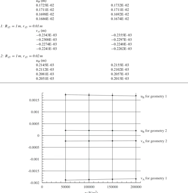
Figure


Documents relatifs
In order to check this prediction, a comparison with exact solutions of the cylindrical bending of the lattice is performed in Section 4. It reveals that only the
In order to give a clear demonstration of the additional warping effects included in the Bending-Gradient theory we compare Kirchhoff-Love, Reissner-Mindlin and Bending-Gradient
The previous paragraph has shown how the elastic potential energy of a rod can be computed following both its centerline and its cross sections orientations, which represents
The GANIL cyclotrons deliver a pulsed ion beam, the frequency of which is in between 8 and 14 MHz and the bunch width less than 2 nanosecond. The aim of this detector is
In [2, 3] Borri and Bottasso thoroughly investigated the idea of replacing the stress-couple resultant m and the specific angular momentum π, which are defined with respect to the
Abstract— The aim of this work is to develop a quadrilateral finite element based on Reddy’s third order shear deformation theory for the bending behavior analysis
Clearly then, by choosing the base width and growth conditions appropriately, it is possible to tune the emission wavelength of individual, site-selected InAs/InP quantum dots close
Frequent attendance in family practice and common mental disorders in an open access health..
