To cite this document:
Kuhn, Nicolas and Van Wambeke, Nicolas and Gineste, Mathieu
and Gadat, Benjamin and Lochin, Emmanuel and Lacan, Jérôme On the Impact of Link
Layer Retransmissions on TCP for Aeronautical Communications. (2013) In: 5th
International Conference on Personal Satellite Services - PSATS 2013, Toulouse, France,
27-28 Jun 2013.
O
pen
A
rchive
T
oulouse
A
rchive
O
uverte (
OATAO
)
OATAO is an open access repository that collects the work of Toulouse researchers and
makes it freely available over the web where possible.
This is an author-deposited version published in:
http://oatao.univ-toulouse.fr/
Eprints ID: 9205
Any correspondence concerning this service should be sent to the repository
administrator:
[email protected]
TCP for Aeronautical Communications
Nicolas Kuhn1,2, Nicolas Van Wambeke3, Mathieu Gineste3, Benjamin Gadat3,
Emmanuel Lochin2, and J´erˆome Lacan2
1
NICTA, Sydney, Australia ([email protected])
2
University of Toulouse, ISAE, TeSA, Toulouse, France ([email protected])
3 Thales Alenia Space (TAS), Toulouse, France
Abstract. In this article, we evaluate the impact of link layer retrans-missions on the performance of TCP in the context of aeronautical com-munications. We present the architecture of aeronautical networks, which is manly driven by an important channel access delay, and the various retransmission strategies that can be implemented at both link and trans-port layers. We consider a worst case scenario to illustrate the benefits provided by the ARQ scheme at the link layer in terms of transmission delay. We evaluate the trade-off between allowing a fast data transmission and a low usage of satellite capacity by adjusting link layer parameters.
Key words: aeronautical communications,ats/aoc services,retransmissions strategies,tcp,link-layer
1 Introduction
According to recent evolutions in the aeronautical communications domain, ad-vanced safety aeronautical communications are composed by two kinds of ser-vice: Air Traffic Services (ATS) and Air Operations Control (AOC), most of these novel services being supported by the SWIM communication paradigm. The goal of such services is to ensure safety and regulate the needs of aeronauti-cal services through the use of binary communication, i.e. transmitting messages between pilots and control centers, instead of actual voice-to-voice communica-tion. ATS/AOC services are small and sporadic, making their transmission over satellite links of interest. In the context of aeronautical communications, the transmission of ATS/AOC services data might be critical and some applications require a reliable transmission with important delay constraints for 95% of the application data.
When channel codes implemented at the physical layer cannot rebuild pack-ets and forward them to the link layer, retransmissions can be introduced to overcome this problem. The multiple retransmission at different layers might decrease the transmission delay and ensure the reliability of the transmission. However, the satellite resource is expensive and must be equally shared among the users.
In this article, we illustrate the trade-off between (1) increasing the reliabil-ity and decreasing the transmission delay by introducing link layer retransmis-sions and (2) using more satellite link capacity. We propose simulations in NS-2 conjointly with a realistic model for the plane-satellite channel. We assess the performance of TCP with and without link layer retransmissions on the return link of the plane in terms of transmission delay and capacity utilization.
The rest of the article is organized as follows: in Section 2, we present the aeronautical communication networks and retransmission strategies that can be introduced at different layers. In Section 3, we present the tools used to simulate the whole protocol stack of elements of such complex network. We consider specific scenarios detailed in Section 4. We present and comment the results of the simulations in Section 5 and then conclude this study in Section 6.
2 Link and transport layers retransmissions in
aeronautical communications
In this section, we present the aeronautical communications network in terms of structure and traffic carried out. We detail the different delays encountered during the transmission of packets. We list available retransmission strategies specifying at which level they can occur.
2.1 Satellite, plane and gateway
In Figure 1, we present the network and highlight the difference between up (also called forward) and down (also called return) links.
000 000 000 000 000 000 111 111 111 111 111 111 00 00 00 00 00 00 11 11 11 11 11 11 Satellite Gateway RF Antenna
up link (forward link)
down link (return link) Ground section
Fig. 1. Plane, satellite and satellite gateway
On the return link (from the plane to the satellite gateway), the average useful throughput is 260 bps, which is enough to transmit the small and sporadic data exchanges required by ATC and AOC services. Each application has specific
requirements in terms of capacity, delay constraint (for 95% of the packets) or availability1. The bounds of these requirements are: (1) the size of data packets
is ranging from 70 to 2500 bytes; (2) the inter-packet time for each application varies from 1000 s to 3000 s; (3) some applications might have delay constraints.
2.2 Channel access delays
The network presented in Section 2.1 is complex due to important delays and medium shared between an important number of users. As a result, we present in this section how we model the channel access delays.
The time needed by an applicative data packet to be transmitted from the client to the server (denoted Tdata) is the sum of the propagation delay (denoted
Tprop), the channel access delay (Tacc) and retransmission delays (Tret):
Tdata= Tprop+ Tacc+ Tret
The propagation time is set to Tprop = 250 ms, which is a standard value for
satellite transmissions.
Forward Return link link Data packets ∈ [10; 100] ∈ [500; 1300]
TCP Ack. 55 900 Table 1. Channel access delay (in ms)
We detail in Table 1 the values of Tacc for both up and return link.
Forward link
At the physical layer of the satellite gateway, the transmission is scheduled by frames. The important size of the antenna enables the gateway to trans-mit frames of 90 ms gathering data for different users. Depending on when the data packet reaches the gateway (will the packet be sent straight away or after 90 ms) and considering the 10 ms necessary for the processing of the frame, we explain the value presented in Table 1 for the forward link. We choose an average delay of 55 ms for the TCP acknowledgements. The channel access delay can be up to 100 ms: as a result, it cannot be neglected compared to the propagation delay for both acknowledgements and data packets.
Return link
In order to obtain capacity, a user terminal on the plane requests for capacity following DAMA VBDC access method. Indeed, the medium is fairly shared between the users as the satellite gateway manages to allow dedicated slots (in terms of transmission date and frequency) for each user. As a result, on
the return link, we consider a delay for the request to be sent to the gateway (between 0 ms and 800 ms), propagation delay for the transmission of the capacity request from the plane to the gateway (250 ms), propagation delay for the resource allocation plan from the gateway to the users (250 ms). We neglect the time needed by the gateway to compute this plan which is very low compared to the propagation delays. We consider an average delay of 900 ms for the TCP acknowledgments.
2.3 Link and transport layers retransmissions
The coding schemes introduced at the physical layer might not be suitable to recover the data when the signal-to-noise ratio is low. As a result, we present in this section the retransmissions schemes introduced at both link and transport layers to ensure a reliable transmission.
At the link layer, there are different retransmission techniques which are presented in [?, ?]. We denote by LLDU the Link Layer Data Unit. Among the different existing techniques, we focus on the two following:
Automatic Repeat reQuest (ARQ)
Automatic Repeat reQuest family can be defined by a subset of retransmis-sion strategies (Stop-and-Wait ARQ, Go-Back-N ARQ or Selective-Repeat ARQ). We consider here SR-ARQ mechanism at the link layer level: it con-sists in the retransmission of the LLDUs that have been lost during the transmission. We denote SR-ARQ by ARQ.
HARQ
Forward Error Correction (FEC) is a scheme where the sender sends a combi-nation of data and repair LLDUs. Let ND(resp. NR) be the number of data
(resp. repair) LLDUs and N = ND+ NR. The process to recover data
LL-DUs is successful if at least NDLLDUs are received, otherwise (if the number
of erasures is strictly greater than NR) no correction is possible. The FEC
scheme does not enable the retransmission of LLDUs. Hybrid-Automatic Re-peat reQuest (HARQ) mechanism is a combination of the FEC and ARQ mechanisms previously described: after the first transmission of a FEC block, including data and repair LLDUs, HARQ allows the sender to transmit ad-ditional repair LLDUs when a recovery is not possible at the receiver side. In other words, if no correction is possible, the transmission of additional repair LLDUs is requested by the receiver. Also, if the receiver requests M LLDU, HARQ can send M + M0, where M0 is the number of supplemen-tary LLDU that can be transmitted, to potentially reduce the number of retransmissions. In the rest of this article, we consider that HARQ does not transmit a first block FEC but still only transmits repair packets to recover the useful data (i.e., NR= 0).
At the transport layer, reliable Transmission Control Protocol (TCP) [?] is considered for on-board applications executing in a SWIM like context while the no retransmission User Datagram Protocol (UDP) [?] is considered for COCR like traffic. There are different variants of TCP [?]. Most of them mostly adapt
the congestion window size in the congestion avoidance phase, however, based on the application sizes detailed in Section 2.1 and the requirements in terms of delay, we focus on TCP New Reno [?] to model the retransmission behaviour as its RFC describes the currently base-line version for TCP. Due to the inter-packet delays considered, TCP never exits the slow-start phase, making the choice for different congestion avoidance mechanism irrelevant.
2.4 Discussion
For safety reasons, reliability is compulsory in both kind of environments and different retransmission strategies can be introduced at both link and trans-port layers (Section 2.3). The transmission delay (including channel access) of retransmissions can be important for both layers (Section 2.2) and some appli-cations have delay constraints (Section 2.1). Moreover, if not properly tuned, introducing retransmissions at multiple layers can lead to counter productive interactions, highly increasing the use of the limited satellite capacity.
In Sections 3,4 and 5, we argue that a trade-off must be found between (1) introducing link layer retransmissions and reducing the transmission delay by using FEC that uses more capacity and (2) no link layer retransmissions, thus leading to a higher end to end transmission delay but using less capacity.
We denote by A the set of applications of each plane, P the set of planes, D one data packet, C(D) and Tdata(D) the exploited capacity and transmission
delay of D, and TM AX(a) the maximum transmission delay authorized for the
application a ∈ A.
∀a ∈ A, ∀p ∈ P, min(C(D), Tdata(D)) (1)
Equation (1) expresses the problem we seek to optimize with the constraint:
Tprop(D) + Tacc(D) < Tdata(D) < TM AX(a),
i.e.
Tret(D) < TM AX(a) − Tprop− Tacc
The objective is thus to adapt the retransmission strategies to reduce Tret(D)
and C(D) for each data packet D.
3 Simulation
In this section, we present the model and simulation of the network.
The work presented herein uses TDM simulators from CNES2. This
simu-lator takes into account realistic satellite links characteristics, such as satellite orbits or recent correcting codes to generate physical layer traces [?]. As a result,
2
CNES is the french government agency responsible for shaping and implementing France’s space policy in Europe, see http://www.cnes.fr/.
each packet transmitted by the physical-layer is characterized by an transmis-sion timestamp and a decoding time. Additionally, its probability to be lost is determined by the physical layer codes and the model of the channel used in the simulation scenario.
Based on the physical layer traces, an simulation of the ARQ or HARQ schemes effects have been derived by the use of the Trace Manager Tool (TMT) [?] that produces link layer traces. These link layer traces are then loaded into the NS-2 network simulation, extended with a Cross-Layer InFormation Tool (CLIFT) [?] to schedule the transmission of applicative packets through the protocol stack (particularly using a specific transport layer) and simulating the behavior of the link and physical layers.
Therefore, with these tools, it is possible to simulate the full protocol stack including link layer FEC, ARQ and HARQ mechanisms to conduct realistic simulations in order to evaluate the impact of retransmissions at the link layer on end to end performances.
4 Scenario
In this section, we present the different retransmissions approaches, the traffic and the metrics that we consider to assess the impact of retransmissions at the link layer when the plane transmits data to the satellite gateway.
Retransmissions
As we detail in Section 2.3, retransmissions can be introduced at different layers of the protocol stack. For compatibility with the SWIM architectures, we argue that the transport layer protocol should be TCP [?]. As a result, we consider the combination of 3 different configuration by varying the link layer reliability mechanism configuration: no retransmission scheme, ARQ at the link layer or HARQ at the link layer.
Traffic
The traffic is generated with exchanges taking place between a plane and a ground system through a satellite gateway (i.e., no air to air com-munication considered). Applications transmit packets of various sizes (∈ [70; 2500] bytes), depending the content carried out and the inter-packet time is different for each application (∈ [1000; 3000] s) (more details can be found in Section 2.1). We consider that there is one TCP connection for each ap-plication executing on-board.
Metrics
The transmission of data at the application level is ensured by a reliable transport layer protocol. Therefore, for each Eb/N 0 ∈ (1.05 dB; 1.3 dB; 1.8 dB) (i.e. LER (Link layer data unit Error Ratio) ∈ 2.3e−1; 6e−2; 2e−4 ) and for each applicative packet size, we measure the transmission delay for 95% of the packets and the mean transmission delay as most applications are delay-sensitive. We also measure the effective coding ratio (defined by the ratio between the applicative data byte transmitted and the total number
of byte transmitted on the air interface) to assess the impact of link layer retransmissions on the usage of the available capacity.
5 Results
In this section, we present the metrics of the simulations defined in Section 4. We focus on the benefits that ARQ can provide when used together with TCP and illustrate a worst-case scenario where HARQ is of interest compared to ARQ.
5.1 On the benefits of ARQ on TCP performance
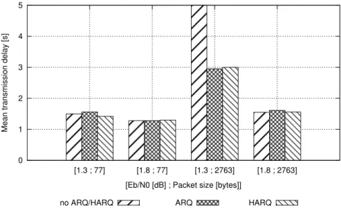
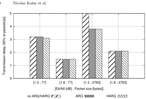
In this subsection, we present the evolution of the metrics when Eb/N 0 ∈ (1.05 dB; 1.3 dB; 1.8 dB). We plot in Figure 2, the mean delay for the trans-mission of one packet, in Figure 3, the transtrans-mission delay of 95% of the packets and in Figure 4, the effective coding ratio.
0 1 2 3 4 5 [1.3 ; 77] [1.8 ; 77] [1.3 ; 2763] [1.8 ; 2763]
Mean transmission del
ay [s]
[Eb/N0 [dB] ; Packet size [bytes]] no ARQ/HARQ ARQ HARQ
Fig. 2. Mean delay
In Figures 2 and 3, we can see that the benefits provided by ARQ at the link layer is not clear in most of the cases. Indeed, as it can be seen, the use of ARQ brings absolutely no benefit for most of the simulations. However, we can see that when the size of the application packets is high (i.e. 2763 bytes) the average delay necessary to transmit a packet is more than 5 s (around 200 s, note that we do not represented this value in order to let the figure readable). We argue
0 1 2 3 4 5 [1.3 ; 77] [1.8 ; 77] [1.3 ; 2763] [1.8 ; 2763] Transmission delay (95 % of packets)[s]
[Eb/N0 [dB] ; Packet size [bytes]] no ARQ/HARQ ARQ HARQ
Fig. 3. Transmission delay of 95% of the packets
0.2 0.25 0.3 0.35 0.4 0.45 0.5 0.55 0.6 [1.3 ; 77] [1.8 ; 77] [1.3 ; 2763] [1.8 ; 2763]
Effective coding ratio [%
]
[Eb/N0 [dB] ; Packet size [bytes]] no ARQ/HARQ ARQ HARQ
Fig. 4. Effective coding ratio
that this specific case is enough to justify the need for retransmission at the link layer when dealing with high PER at link layer.
However, as we discussed in Section 2.4, Figure 4 shows that in this example (large packets in high PER conditions), in order to decrease the transmission
de-lay, more capacity is exploited to transmit one single data packet thus increasing the risk of jamming the system in high load conditions.
As shown, in some specific use cases, link layer retransmissions are beneficial. This experiments also show that this link layer retransmissions have a cost in terms of capacity usage. However, results of this section do not highlight differ-ences between ARQ and HARQ link layer retransmissions schemes, which we focus on in Section 5.2.
5.2 Comparison of ARQ and H-ARQ on TCP performance
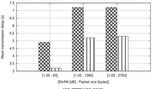
The results presented in Section 5.1 do not reveal any advantage for or against ARQ and HARQ implementations at the link layer. We present additional sim-ulations in this section, with a higher PER at physical layer and considering various size of applicative packets. We plot in Figure 5 the transmission delay of 95% of the packets and in Figure 6, the effective coding ratio. As we compare ARQ and HARQ, we focus on a specific implementation of HARQ. HARQ does not transmit a first FEC block, but introduce more additional retransmission packets than ARQ (more details can be found in Section 2.3).
3 3.5 4 4.5 5 5.5 6 6.5 7 7.5 [1.05 ; 93] [1.05 ; 1380] [1.05 ; 2763]
Mean transmission del
ay [s]
[Eb/N0 [dB] ; Packet size [bytes]] ARQ HARQ
Fig. 5. Transmission delay of 95% of the packets
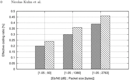
We measure that HARQ can reduce the transmission delay of ARQ on several cases (in Figure 5), making their use of interest in case of a very noisy channel. However, this improvement has a cost in terms of capacity usage as illustrated in Figure 6.
0 0.05 0.1 0.15 0.2 0.25 0.3 0.35 0.4 0.45 0.5 [1.05 ; 93] [1.05 ; 1380] [1.05 ; 2763]
Effective coding ratio [%
]
[Eb/N0 [dB] ; Packet size [bytes]] ARQ HARQ
Fig. 6. Effective coding ratio
Considering a specific HARQ reduces the scope of our results, but we high-light the need for deeper studies on the impact of the parameters of HARQ on the TCP performance in the context of critical aeronautical communications. We illustrate that different link layer retransmission schemes have different per-formances in terms of delay and capacity utilization, illustrating the discussion presented in Section 2.4.
5.3 Limits of interpretations
The considered physical layer performances are located well below the currently defined targets for satellite communication systems used in aeronautical com-munications. For systems which are well designed, and for which the physical layer performances meet the established criterion, the use of ARQ and HARQ at the link layer does not provide any improvement when compared to the use of TCP without any link layer retransmissions.
Furthermore, the use of SWIM like communication paradigms, heavily rely-ing on protocols such as HTTP and SOAP make the use of TCP a natural choice. In these contexts, although the introduction of ARQ and HARQ can improve the performance in high PER contexts, the overall transmission delays observed (even in a fully optimized context) are not compliant with the application re-quirements. Finally, the presence of timeout values in protocols executing above TCP have not been considered in this study.
6 Conclusion
In this article, we argue for the introduction of link layer retransmissions schemes in the context of aeronautical communications. We make use of link layer simula-tion traces on which we simulate link layer retransmissions to assess the impact on ARQ and HARQ on the performance of TCP. We show that, in worst cases with regards to the propagation channel conditions, link layer retransmissions enable to transmit applicative data in acceptable delays for the safety of aeronau-tical communications. We also illustrate that a trade-off must be found between having a low transmission delay and a good channel capacity usage.
7 Acknowledgments
This work presented in this article documents part of the simulation scenarios and results obtained in a study funded by CNES in which T´eSA and Thales Alenia Space took part.
References
1. S. Lin and D. J. Costello, Error control coding: fundamentals and applications, vol. Chapter 15. Ed. Prentice-Hall, 1983.
2. E. Berlekamp, R. Peile, and S. Pope, “The application of error control to commu-nications,” Communications Magazine, IEEE, vol. 25, pp. 44 –57, april 1987. 3. J. Kurose and K. Ross, “A top-Down Approach,” in Computer Networking, p. 284,
Ed. Addison Wesley, 2008.
4. J. Postel, “User Datagram Protocol,” RFC 768, RFC Editor, Aug. 1980.
5. C. Callegari, S. Giordano, M. Pagano, and T. Pepe, “Behavior analysis of tcp linux variants,” Comput. Netw., vol. 56, pp. 462–476, Jan. 2012.
6. M. Allman, V. Paxson, and E. Blanton, “TCP Congestion Control,” RFC 5681, RFC Editor, Fremont, CA, USA, Sept. 2009.
7. W. Chauvet, C. Amiot-Bazile, and J. Lacan, “Prediction of performance of the dvb-sh system relying on mutual information,” in Advanced satellite multimedia systems conference (asma) and the 11th signal processing for space communications workshop (spsc), 2010 5th, pp. 413 –420, sept. 2010.
8. N. Kuhn, E. Lochin, J. Lacan, R. Boreli, C. Bes, and L. Clarac, “Enabling realistic cross-layer analysis based on satellite physical layer traces,” in PIMRC’12, pp. 285– 290, 2012.
9. N. Kuhn, E. Lochin, J. Lacan, R. Boreli, C. Bes, and L. Clarac, “Clift: a cross-layer information tool to perform cross-cross-layer analysis based on real physical traces,” CoRR, vol. abs/1206.5459, 2012.