of a cylindrical journal bearing
in the starting phase
Kadda Mehala, Nadia Bendaoud and Abdelkader Youcefi
University of Sciences and Technology, Mohamed Boudiaf, El Menaour, Oran, Algeria
AbstractPurpose – The paper aims to analyze the evolution of the lubrication regime by studying the variation of friction coefficient with the rotational speed of the shaft and the impact of the applied load in the starting phase of a cylindrical journal bearing. The paper also aims to ensure that the oil layer is large enough for the rough edges of the outer layer of the bushing and the shaft cannot come into contact. The bearing is made of steel backing material and babbitted (88 per cent tin) on its inner surface.
Design/methodology/approach – A numerical analysis is performed taking into account the thermal effect to better predict the operating performance of a hydrodynamic plain cylindrical journal bearing during the start-up and observe the variation of the heat production in bushing inner surface. The flow is modeled based on the Reynolds equation and discretized using the finite volume method.
Findings – The evolutions of the start-up speeds of the bearing have remarkable influence on friction torque; average temperature and dissipated power increased with increasing speed and increasing load, but the maximum pressure and the eccentricity decreased with the increase of the start-up speed. The friction coefficient, minimum film thickness and attitude angle increase with elevation of start-up speed.
Originality/value – For the start-up speed of 750, 1,000 and 1,800 rpm and an applied load of 1,000 N, the regime of lubrication of the bearing passes the hydrodynamic regime to the mixed regime; therefore, during start-up and under heavy loads, the bearing must move very quickly at these speeds to avoid contact of the inner surface of the bearing and the shaft.
Keywords Plain cylindrical journal bearing, Friction coefficient starting phase, Lubrication regime, Thermal effect Paper type Research paper
Nomenclature
C ⫽ bearing clearance [m] Cp ⫽ specific heat [J/kg·k]
CB ⫽ friction torque of the bushing [Nm] e ⫽ eccentricity of the shaft in the bearing [m] h ⫽ film thickness [m]
K ⫽ thermal conductivity of the fluid [w/mK] L ⫽ bearing length [m]
m, n ⫽ coefficients of McCoull and Walther relationship OB ⫽ bush center Os ⫽ shaft center p ⫽ pressure [MPa] RB ⫽ bushing radius [m] Rs ⫽ shaft radius [m] T ⫽ fluid temperature [°C] T0 ⫽ initial temperature [°C]
UB ⫽ bushing speed along the X-axis [m/s] Us ⫽ shaft speed along the X-axis [m/s]
u, v, w ⫽ velocity components in the fluid film [m/s]
W ⫽ radial load [N]
x, y, z ⫽ Cartesian coordinate [m]
␣ ⫽ coefficient of thermal expansion [1/K] ␦ ⫽ thermoelastic component [m] ⫽ relative eccentricity ⫽ e/C ⫽ attitude angle [rad] ⫽ dynamic viscosity [Pa·s] ⫽ circumferential coordinate [rad] r ⫽ angular coordinate in rupture zone ⫽ oil density [kg/m3
] ⫽ angular speed [rad/s]
B ⫽ angular speed of the buching [rad/s] S ⫽ annular speed of the shaft [rad/s]
1. Introduction
Cylindrical journal bearings have been widely used in industrial applications for more than a century. However, their thermohydrodynamic (THD) behavior in transient regime (i.e. during start-up of the bearing) has recently been investigated, as bearing performance is definitely impacted in transient periods, due to sudden main parameter changes such as speed or load. The relevance of thermal effects in lubricated mechanism in the transient regime was recognized by the early works ofEzzat and Rhode (1974)andEttles et al. (1988). In their paper, Khonsari and Wang (1992) have exposed a simplified analysis of bearing in transient regime. Discarding the speed component, they uncoupled energy equation and Reynolds equation. Also, they took simplified boundary adiabatic and thermal states into consideration. The The current issue and full text archive of this journal is available at
www.emeraldinsight.com/0036-8792.htm
Industrial Lubrication and Tribology 66/3 (2014) 379 –386
© Emerald Group Publishing Limited [ISSN 0036-8792] [DOI10.1108/ilt-05-2012-0046]
theoretical results have concluded that equilibrium is reached in a very short period (around 0 and 2 seconds).
A comprehensive study of transient THD effects on bearing submitted to dynamic loads was realized byParanjpe and Han (1994), considering heat flow continuity at the fluid–solid interface.
Monmousseau et al. (1997)presented an analysis in 1997, a complete thermoelastohydrodynamic model in transient regime for a tilting-pad journal bearing which takes into account the heat flux continuity at the oil film–solid interfaces. Kucinschi et al. (2000)propose an advanced bi-dimensional model necessary to calculate the temperature field in a journal bearing submitted to both rapid and slow start-ups. Their model takes into account realistic thermal boundary conditions at fluid film–solid interfaces.
Wang et al. (2005) presented a numerical analysis of a tilting-pad thrust bearing during start-up in 2005. They studied both the effects of start-up time and start-up load on the temperature distribution in the oil film. They showed that the fluid film forms quickly at the beginning of the start-up procedure and also that the film temperature is lower in a rapid start-up than in a slower start-up.
Bouyer and Fillon’s study (2008) provided experimental measurements of the bush torque during start-up, for transient regime, by applying various static loads and start-up accelerations. They showed that the torque is very sensitive to oil temperature. For low static loads, the acceleration time has no influence on the maximum torque recorded during start-up. Three years later, Bouyer and Fillon (2011) presented an experimental measurement of the friction torque on hydrodynamic plain journal bearings during start-up.
The present study investigates the effect of temperature in transient regime by resolution of the energy equation with the finite difference method. This analysis studied the impact of start-up speed and radial load on operating characteristics of the bearing because the rotation start-up speed of the journal bearing is too slow to generate sufficient hydrodynamic pressure to support the load. Besides to follow the evolution of the Lubrication regime of a cylindrical journal bearing, while calculating the coefficient of friction, using the classification of various lubrication phenomena which was presented for the first time in 1902 in the Stribeck curve a journal bearing (Stribeck, 1902).
2. Theoretical analysis
2.1 Reynolds equationThe pressure field is determined by the resolution of the generalized Reynolds equation in transient regime-starting phase (1) under classic assumptions in the (O,¡, z¡) coordinate system. Figure 1 illustrates the schematization of plain cylindrical journal bearing.
⭸ ⭸
共
h3⭸p⭸兲
⫹共
R L兲
2⭸ ⭸z共
h3⭸p⭸z兲
⫽ 12 LD W共
C R兲
2 ⫻关共 ⫺ 兲 sin ⫹ cos 兴 (1) To determine pressure field, Reynolds boundary conditions are used. They are shown as follows:For bearing:
p共, ⫾L/2兲⫽ 0 (2)
At the limit of the rupture zone, the Reynolds conditions apply:
p共r兲⫽ ⭸ p
⭸
兩
⫽r⫽ 0 (3)ris the angular coordinate in rupture zone: With: ⫽S⫹B
2 (4)
is the average angular speed of the shaft and the bearing to the load.
The viscosity variation as a function of temperature is obtained by the McCoull and Walther (1921) relationship with a⫽ 0.6 and m and n being two coefficients calculated from two values of the dynamic viscosity of the lubricant at different temperatures:
log10log10
关
(T) ⫹a
兴
⫽ m log10(T)⫹ n (5) 2.2 The temperature fieldThe temperature field in the lubricant film is calculated from the energy equation (6). The details of this part are to be found in a previous work byPierre and Fillon (2000):
CP
共
u R ⭸T ⭸ ⫹ ⭸T⭸y ⫹w⭸ T ⭸z兲
⫽ K⭸ 2T ⭸y2 ⫹关共
⭸u ⭸y兲
2 ⫹共
⭸w⭸y兲
2兴
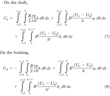
(6) 2.3 Friction torqueThe calculation of the friction torque is done by integrating the shear stress at the shaft surface (y⫽ h) or (y ⫽ 0). Figure 1 Schematization of plain journal bearing
On the shaft, CS⫽
兰
⫺L/2 ⫹L/2兰
e s R 2 ⭸p ⭸h d dz ⫹兰
⫺L/2 ⫹L/2兰
e S R2(US⫺ UB) h d dz ⫹兰
⫺L/2 ⫹L/2兰
s e⫹ R2(US⫺ UB) h2 hsd dz (7) On the bushing, CB⫽ ⫺兰
⫺L/2 ⫹L/2兰
e s R 2 ⭸p ⭸h d dz ⫹兰
⫺L/2 ⫹L/2兰
e s R2(US⫺ UB) h d dz ⫹兰
⫺L/2 ⫹L/2兰
s e⫹ R2(US⫺ UB) h2 hsd dz (8)Velocities UBand Usare given by the expressions below: For shaft,
U
S⫽ e sin ⫺ e( ⫹ )cos ⫹ RSS⬵ RSS (9) For bushing,U
B⫽ RBB (10)Where hsis the height of the oil film for ⫽ s·eandsare the input and output limits, respectively, of the oil film. The interval [e,s] defines the active area of the film (pⱖ 0) and [s,e⫹2] is the inactive zone of the film (p⫽ 0).
The friction coefficient (f) is calculated with the following formula:
f⫽ CB RB·W
(11)
The term RBis the bushing radius.
3. Numerical resolution of THD effect on
transient regime of the circular journal bearing
In this section, an analysis is exposed relative to start-up speed of the shaft and applied load for a cylindrical journal bearing. We also make a predictive assessment of the THD behavior of a lubricated mechanism. The ANSYS CFX Code has been used to obtain pressure field distribution through a resolution of the energy equation, pertaining to the difference finite method. This method solves the differential equations that govern fluid flow. The integration of the Reynolds equations on each control volume to derive an equation linking the discrete variables of the elements surrounding all these equations eventually forms a matrix system. CFX-5.7 uses an algorithm called “coupled solver” that solves the hydrodynamic equations (for u, v, w, P and T) as a single system. The numerical method is detailed in the document ANSYS CFX-Solver Theory (2003); this algorithm makes use of the interpolation method of Rhie and Chow (1982) to prevent disturbance of the field pressure. This method isamong the best methods to save memory space and computing time.
3.1 Numerical resolution strategy
The numerical resolution strategy of an ANSYS CFX code is as follows:
● modeling of the structure, meshing; ● modeling of the load;
● solving Reynolds equation by the finite difference method; ● calculation of the pressure field;
● solving the interpolation equations and calculation of overall structure stiffness matrix;
● calculation of displacement, strain; and
● calculation of operating characteristics of the bearing.
3.2 Geometrical model creation
The shaft made of steel is driven by an electric motor of 21 kW with a diameter of 99.82 mm, a bushing of an internal diameter of 100 mm and an external diameter of 140 mm (Figure 2). This results in a bearing with a radial clearance of 90m.
The first bearing layer is a 38-mm thick steel structure, whereas the second layer internal is a low-friction material (tin) with a thickness of 2 mm (88 per cent Babbitt ASTM B23-949).
3.3 Geometric discretization
As most of the pre-processor computer codes finite element or finite difference, the geometric model is created: first, the definition of the geometry (points, lines, surfaces and volumes), and second, the generation of the mesh. The computational domain is discretized into a fixed number of adjacent finite volumes by using the finite volume method. The mesh of the computational domain and the choice of mesh elements are determined by the geometric shape.
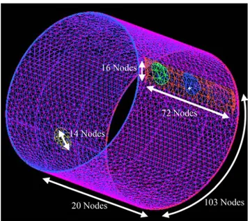
The physical domain shown inFigure 3is discretized into volume tetrahedral elements form.
Figure 3 corresponds to the mesh of the hydrodynamic bearing. This mesh has 20 nodes along the bearing and 103 nodes for its circumference. The diameter of the supply ports is discretized into 14 nodes. The length of the groove consists of 72 Figure 2 Representation of the studied geometry
2 mm layers out of antifriction steel Bearing
Groove with 3 openings
Feeding for loading system
nodes, 16 nodes for its width and five nodes along the depth of the groove. The film thickness is discritized by six nodes. The mesh consists of 30,433 elements and 74,163 nodes.
For the boundary conditions (Figure 4), a supply pressure is applied in the three supply ports while assuming that the inlet and outlet of the fluid with a temperature of 60°C and in the pressure of 0.04 MPa, except the shaft is considered to be a rotating element. However, the bushing is recessed on its outer diameter. The loading system is simulated by an orifice of diameter of 14 mm, and the direction of the fluid inlet is the same radial load direction with variable pressures calculated by the ratio of the load on the bearing surface, with temperature of 60°C.
3.4 Results and discussions
Numerical simulation is carried out to find the limits of the THD model when the bearing is operating under start-up rotational speed. Bearing and lubricant characteristics and operating conditions are presented inTable I. The mechanical and thermal characteristics of the bearing elements are given inTable II.
The operating conditions are a feeding temperature of 60°C and a supply pressure of 0.04 MPa. The radial load varies from 1 to 20 kN and rotational speed varies from 150 to 1,800 rpm. The study will try to show which values of start-up rotational speed and radial load are required on the operating parameters of the bearing for the THD model.
3.4.1 Influence of rotational speed and applied loads
To analyze the influence of start-up speed of shaft and applied load on the operating parameter of the bearing and on the relevance of the use of the THD simulation, a bearing subjected to a radial load ranging from 1,000 to 20,000 N and rotational speeds ranging from 150 to 1,800 rpm has been chosen. The analyses were carried out at a feeding oil temperature of 40°C and a supply pressure of 0.08 MPa. The pressure distribution in bearing median plane; in a case where bearing is running at a start-up rotational speed of 150-1,800 rpm and for an applied load of 1,000 N, as shown inFigure 5. It is noted that pressure is very significant at low speeds and it reduces when the start-up speed increases.
Figure 6 illustrates a three-dimensional view of the circumferential distribution of pressure field in mid-plane of bearing for three directions x, y and z at a feeding temperature of 60°C and a supply pressure of 0.08 MPa, for a rotation speed of 750 rpm and a radial load of 1,000 N. The figure clearly shows that the maximum pressure is at the angular position of 180°, and the peak of the pressure profile is located near the zone of minimum film thickness. We notice that at Figure 3 Mesh bearing
Table I Geometrical characteristics of the journal bearing, lubricant
characteristic and operating conditions
Bearing diameter D (mm) 100
Bearing length L (mm) 80
Radial clearance C (mm) 0.09
Length of supply groove Lg (mm) 70
Feeding hole diameter do (mm) 14
Lubricant type PM3
Density of oil (kg/m3) 800
Specific heat of lubricant Cp (j/kgK) 2000
Oil viscosity at 40°C 1(mma/s) 17.49
Oil viscosity at 80°C 2(mma/s) 8.003
Rotational speed N (r/min) 150-1800
Radial load W (kN) 1-20
Feeding temperature Ta (°C) 60
Supply pressure Pa (MPa) 0.04
Table II Bearing element characteristics
Thermal conductivity of the bushing KB(W/mK) 45
Specific heat of the bush CB(J/kgK) 380
Bushing thermal expansion coefficient ␣B(10⫺5K⫺1) 1.2
Bushing Poisson coefficient B 0.33
Bushing Young modulus EB(104MPa) 12 Figure 4 Computational domain
the angular positions of 200° and 250°, the geometry of the film becomes divergent and film rupture takes place. Here the pressure starts being sub-ambient.
Figure 7 presents the maximum pressure variation vs the start-up rotational speed, and under applied loads 1-20 k for feeding temperature of 60°C and supply pressure of 0.4 MPa. The maximum pressure is 42.136 MPa; this pressure is obtained in a case where bearing is running at a rotation speed of 150 rpm, with a radial load of 20,000 N. The start-up speed increase will lead to a pressure reduction of 47 per cent under an applied load of 20 kN. On the other hand, in the case of a bearing submitted to a load of 1 kN, maximal pressure shows a less significant reduction of 2 per cent with a start-up speed increase.
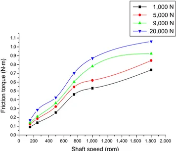
The friction torque has been obtained assuming that all the bearing filled with lubricant. The effect of start-up velocity on friction torque distribution is presented inFigure 8. It is noted that the friction torque increases with rotational speed. The results show that the friction torque due to action of the bushing surface increases significantly with increasing speed, which causes heating and reduction of the oil viscosity. The
friction torque values are significant for a rotational speed case of 1,800 rpm and for a radial load of 20 kN; the maximal value is estimated of 1.062 Nm.
Variation of the average temperature in the fluid according to the start-up rotational velocity of the shaft and for applied loads of 1,000, 5,000, 9,000 and 20,000 N is demonstrated in Figure 9 for a feeding temperature of 60°C and a supply pressure of 0.4 MPa. As can be seen in Figure 9, the temperature increases with the increase in shaft speed. For an applied load of 1,000 N, the temperature increases from 60.5 to 62.5°C with increase of the start-up velocity.
Figure 10 presents the variation of the friction coefficient according the start-up rotational speed and for radial loads of 1,000-20,000 N. We can see that for speed (150-1,800 rpm), and under a radial load (1,000 N), friction coefficient has a highest increase (0.002-0.0104), is estimated of 50 per cent. In this case, the lubricant layer is discontinuous because the coefficient is 0.00104; this value is between 0.008 and 0.12 (the Figure 5 Pressure in median plane for transient THD analysis
0 50 100 150 200 250 300 350 0.4 0.3 0.2 0.1 0 −0.1 −0.2 −0.3 −0.4 Load 1,000 N 150 rpm 250 rpm 500 rpm 750 rpm 1,000 rpm Pressure (MPa) Angular coordinate (º)
Figure 6 Three-dimensional distribution of pressure in bearing median plane for transient THD analysis
0 20 40 60 80 0 50 100 150 200 250 300 350 −2 −1.5 −1 −0.5 0 0.5 1 1.5 2 2.5 Angular coordinate (º) P res su re (MP a) Axial direction (mm)
Figure 7 Maximum pressure vs rotational speed for load (1,000-20,000 N) 0 200 400 600 800 1,000 1,200 1,400 1,600 1,800 2,000 45 40 35 30 25 20 15 10 5 0 1,000 N 5,000 N 9,000 N 20,000 N
Maximum pressure (MPa)
Shaft speed (rpm)
Figure 8 Friction torque vs shaft rotational speed for applied load (1,000-20,000 N) for THD calculation 0 200 400 600 800 1,000 1,200 1,400 1,600 1,800 2,000 0,0 0,1 0,2 0,3 0,4 0,5 0,6 0,7 0,8 0,9 1,0 1,1 1,000 N 5,000 N 9,000 N 20,000 N Friction torque (N·m) Shaft speed (rpm)
mixed regime). In this case, the thickness of the lubricating layer is less than the height of the roughness of the inner layer of the bushing and the shaft. The surfaces remain in contact by their roughness which causes a considerable mechanical resistance to crushing and tearing. This cycle, repeated, tends to induce overheating. With hydrodynamic lubrication, a rise in the temperature which reduces the viscosity will reduce the friction factor, thus reducing the heat generated. This cycle tends to produce a stable operating temperature.
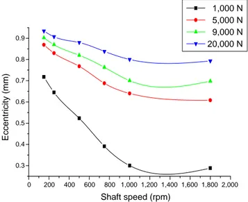
For another case, the oil layer, large enough for the rough parts, may not come into contact because the friction coefficient is quite low and does not exceed 0.001 (hydrodynamic regime). The eccentricity variation of the shaft in the bearing is illustrated inFigure 11for the speed case of 1,800 rpm, and
for the applied load of 1,000 N, the eccentricity is not as low and an increase of the start-up speed of the shaft causes an estimated sharp reduction of eccentricity by 30 per cent. Attitude angle variation vs shaft rotational speed, for an applied load (1,000-20,000 N), for THD calculation is presented inFigure 12. Curves show an increase of 5 per cent of the attitude angle for loads 5,000, 9,000 and 20,000 N with a rotational speed variation of 150-1,800 rpm and an increase of 20 per cent for an applied load of 1,000 N.
The relationship between start-up speed and dissipated power that has been performed at a temperature of the feed oil of 60°C, pressure of 0.04 MPa supply and under loads of 1,000-20,000 N is given in Figure 13. This figure clearly shows that the variation of shaft speed of 150-1,800 rpm Figure 9 Average temperature vs rotational speed for load
(1,000-20,000 N) 200 400 600 800 1,000 1,200 1,400 1,600 1,800 2,000 60.0 60.5 61.0 61.5 62.0 62.5 63.0 1,000 N 5,000 N 9,000 N 20,000 N Average temperature (º) Shaft speed (rpm)
Figure 10 Friction coefficient vs shaft rotational speed for applied load (1,000-20,000 N) for THD calculation
0 200 400 600 800 1,000 1,200 1,400 1,600 1,800 2,000 0.000 0.002 0.004 0.006 0.008 0.010 0.012 1,000 N 5,000 N 9,000 N 20,000 N Friction coefficient Shaft speed (rpm)
Figure 11 Eccentricity variation vs shaft rotational speed for applied load (1,000-20,000 N) for THD calculation
0 200 400 600 800 1,000 1,200 1,400 1,600 1,800 2,000 0.3 0.4 0.5 0.6 0.7 0.8 0.9 1,000 N 5,000 N 9,000 N 20,000 N Eccentricity (mm) Shaft speed (rpm)
Figure 12 Attitude angle variation vs shaft rotational speed for applied load (1,000-20,000 N) for THD calculation
0 200 400 600 800 1,000 1,200 1,400 1,600 1,800 2,000 15 20 25 30 35 40 45 50 55 60 65 70 1,000 N 5,000 N 9,000 N 20,000 N Attitude angle (º) Shaft speed (rpm)
causes elevation of dissipated power of 3-200 W. The maximum value is noted in the case of an applied load of 20,000 N and a start-up speed of 1,800 rpm.
Figure 14 illustrates the evolution of the minimum film thickness according the start-up rotational speed of the shaft for an angular position of 180°. The minimum value of film thickness is noted for an applied load of 20,000 N. We can observe that the increase start-up speed of the tree caused a slight increase in film thickness, from 9.5 to 28.9 m (estimated 23 per cent) for the radial load of 20,000 N. In contrast, for an applied load of 1,000 N, the increase is from 38 to 81m (53 per cent).
3.4.2 Relevance of the THD model
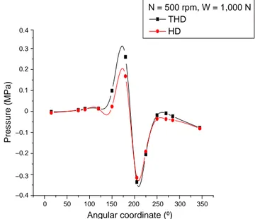
In this paragraph, two different simulations are compared: an isothermal simulation (HD) at the feeding temperature (60°C) and a THD simulation (THD) that takes into account the local thermal effect. At the starting phase of the bearing, the rotational speed is 500 rpm and radial load is 1,000 N. The operating conditions are presented inTable I.
The maximum pressure is affected by thermal effect; it increases by⬎ 10 per cent, as can been seen inFigure 15. This is due to the decrease in viscosity and, consequently, the increase in eccentricity. However, the minimum film thickness shown in Figure 16 is the most modified. The HD simulation underestimates the minimum film thickness (by 10 per cent) because it does take into account the thermal effect.
Figure 14 Minimum film thickness vs shaft rotational speed for applied load (1,000-20,000 N) for THD calculation
0 200 400 600 800 1,000 1,200 1,400 1,600 1,800 2,000 0,01 0,02 0,03 0,04 0,05 0,06 0,07 0,0880 70 60 50 40 30 20 10 1,000 N 5,000 N 9,000 N 20,000 N
Minimum film thickness (
µ
m)
Shaft speed (rpm)
Figure 15 Circumferential repartition of pressure in mid-plane of the bearing for THD and HD calculations
0 50 100 150 200 250 300 350 0.4 0.3 0.2 0.1 0 −0.1 −0.2 −0.3 −0.4 N = 500 rpm, W = 1,000 N THD HD Pressure (MPa) Angular coordinate (º)
Figure 16 Circumferential repartition of minimum film thickness for THD and HD calculations 0 50 100 150 200 250 300 350 140 120 100 80 60 40 THD HD
Minimum film thickness (
µ
m)
Angular coordinate (º)
Figure 13 Dissipated powers vs shaft rotational speed for applied load (1,000-20,000 N) for THD calculation
0 200 400 600 800 1,000 1,200 1,400 1,600 1,800 2,000 −20 0 20 40 60 80 100 120 140 160 180 200 220 1,000 N 5,000 N 9,000 N 20,000 N Dissipated power (W) Shaft speed (rpm)
4. Conclusion
This article presents a study dedicated to the identification of different operating characteristics of cylindrical journal bearing in starting phase. For this purpose, we solve the unsteady Reynolds equation by using the numerical finite difference method. This work led to the following conclusions: ● The consideration of thermal effects showed that the maximum pressure has a remarkable increase and reached almost 50 per cent, which is largely overestimated by HD simulation. The thermal effects have a considerable influence on the minimum film thickness.
● The evolutions of the start-up speeds of the bearing have remarkable influence on friction torque; average temperature and dissipated power increased with increasing speed and increasing load, but the maximum pressure and eccentricity decreased with increase of the start-up speed.
● The friction coefficient, minimum film thickness and attitude angle increase with elevation of start-up speed. ● For the start-up speed of 750, 1,000 and 1,800 rpm and an
applied load of 1,000 N, the regime of lubrication of the bearing passes the hydrodynamic regime to the mixed regime; therefore, during start-up and under heavy loads, the bearing must move to these speeds very quickly, to avoid contact of the inner surface of the bearing and shaft.
References
ANSYS-CFX 6.7 (2003), Documentations Solver Theory/ Turbulence and Near Wall Theory, ANSYS.
Bouyer, J. and Fillon, M. (2008), “Behaviour of a hydrodynamic journal bearing: torque measurement during start-up”, The Annals of University “Dunarea de Jos” of Galati, Fascicle VIII, ISSN 1221-4590, Tribology, pp. 53-57.
Bouyer, J. and Fillon, M. (2011), “Experimental measurement of the friction torque on hydrodynamic plain journal bearings during start-up”, Tribology International, Vol. 44 Nos. 7/8, pp. 772-781.
Ettles, C.M.M., Heshmat, H. and Brockwell, K.R. (1988), “Elapsed time for the decay of thermal transients in fluid film bearing assemblies”, Proceeding of 15th Leeds-Lyon Symposium on Tribology, pp. 229-235.
Ezzat, H.A. and Rohde, S.M. (1974), “The transient in finite sliderbearings”, ASME Journal of Lubrication Technology, Vol. 96 No. 3, pp. 315-320.
Khonsari, M. and Wang, S.H. (1992), “Note of transient THD effects in a lubricating film”, Tribology Transaction, Vol. 35 No. 1, pp. 177-183.
Kucinschi, R.B., Pascovici, M., Fillon, M. and Frene, J. (2000), “A transient thermoelastohydrodynamic study of steadily loaded plain journal bearings using finite element method analysis”, ASME, Journal of Tribology, Vol. 122 No. 1, pp. 219-226.
McCoull, N. and Walther, C. (1921), “Viscosity- temperature chart”, Lubrication, June.
Monmousseau, P., Fillon, M. and Fêne, J. (1997), “Transient thermoelastohydrodynamic study of tilting-pad journal bearing-comparison between experimental data and theoretical results”, ASME Journal of Tribology, Vol. 119, pp. 401-407.
Paranjpe, R.S. and Han, T. (1994), “A study of the thermoelastohydrodynamic performance of steadily journal bearing”, Tribology Transaction, Vol. 37 No. 1, pp. 679-690. Pierre, I. and Fillon, M. (2000), “Influence of geometric
parameters and operating conditions on the
thermohydrodynamic behaviour of plain journal bearings”, Proceeding of the Institution of Mechanical Engineers, Part J: Journal of Engineering Tribology, Vol. 214 No. 5, pp. 445-457.
Rhie, C.M and Chow, W.L. (1982), “A numerical study of the turbulent flow past an isolated airfoil with trailing edge separation”, AIAA, pp. 1525-1532.
Stribeck, R. (1902), “Die wesentlichen Eigenschaften der Gleit-und Rollenlager”, Z. Verein. Deut. Ing, Vol. 46 No. 38, pp. 1341-1348.
Wang, X., Zhang, Z. and Pan, J. (2005), “A transient thermo-elastohydrodynamic analysis of a tilting-pad thrust bearing during start-up”, Proceeding of WTC2005, Paper WTC2005-63925, 12-16 September, Washington DC.
Corresponding author
Kadda Mehala can be contacted at: Postegraduation@ yahoo.com
To purchase reprints of this article please e-mail:[email protected]