HAL Id: hal-03066422
https://hal.archives-ouvertes.fr/hal-03066422
Submitted on 15 Dec 2020HAL is a multi-disciplinary open access
archive for the deposit and dissemination of sci-entific research documents, whether they are pub-lished or not. The documents may come from teaching and research institutions in France or abroad, or from public or private research centers.
L’archive ouverte pluridisciplinaire HAL, est destinée au dépôt et à la diffusion de documents scientifiques de niveau recherche, publiés ou non, émanant des établissements d’enseignement et de recherche français ou étrangers, des laboratoires publics ou privés.
Si and Ge-Based Anode Materials for Li-, Na-, and
K-Ion Batteries: A Perspective from Structure to
Electrochemical Mechanism
Laura Loaiza, Laure Monconduit, Vincent Seznec
To cite this version:
Laura Loaiza, Laure Monconduit, Vincent Seznec. Si and Ge-Based Anode Materials for Li-, Na-, and K-Ion Batteries: A Perspective from Structure to Electrochemical Mechanism. Small, Wiley-VCH Verlag, 2020, 16 (5), pp.1905260. �10.1002/smll.201905260�. �hal-03066422�
Si and Ge-based anode materials for Li-, Na- and K-ion batteries: a
perspective from structure to electrochemical mechanism.
Laura C. Loaiza, Laure Monconduit, Vincent Seznec*,
Author 1, Laura C. Loaiza
A. Laboratoire de Réactivité et Chimie des Solides (CNRS UMR 7314), Université de
Picardie Jules Verne, 33 Rue Saint Leu, 80039 Amiens Cedex, France.
Author 2, Laure Monconduit
B. Institut Charles Gerhardt Montpellier, Université de Montpellier, CNRS, 34095
Montpellier, France.
C. Réseau sur le Stockage Electrochimique de l’Energie (RS2E), CNRS FR3459, 33
Rue Saint Leu, 80039 Amiens, Cedex, France
D. ALISTORE European Research Institute, Université de Picardie Jules Verne, 33 rue
Saint Leu, 80039 Amiens Cedex, France
Author 3, Vincent Seznec, corresponding author
A. Laboratoire de Réactivité et Chimie des Solides (CNRS UMR 7314), Université de
Picardie Jules Verne, 33 Rue Saint Leu, 80039 Amiens Cedex, France.
C. Réseau sur le Stockage Electrochimique de l’Energie (RS2E), CNRS FR3459, 33
Rue Saint Leu, 80039 Amiens, Cedex, France
D. ALISTORE European Research Institute, Université de Picardie Jules Verne, 33 rue
Saint Leu, 80039 Amiens Cedex, France
E-mail: vincent.seznec@u-picardie.fr
Abstract
Silicon and germanium are among the most promising candidates as anodes for Li-ion batteries, meanwhile their application in Sodium- and Potassium-ion batteries is emerging. The access of their entire potential requires a comprehensive understanding of their electrochemical mechanism. This review highlights the processes taking place during the alloying reaction of Si and Ge with the alkali ions. Several associated challenges, including the volumetric expansion, particle pulverization and uncontrolled formation of SEI layer, must be surmounted and different strategies, such as nanostructures and electrode formulation, have been implemented. Additionally, a new approach based on the use of layered Si and Ge-based Zintl phases is presented. The versatility of this new whole family permits the tuning of their physical and chemical properties for specific applications. Particularly for batteries the layered structure buffers the volume expansion and exhibits an enhanced electronic conductivity allowing high power applications.
1 Introduction
Lithium ion batteries are the first choice of energy storage devices for portable applications. Among all the metals Li has the smallest atomic weight and the lowest density, which combined with a low reduction potential makes it a suitable electrode material for battery use (Erreur ! Source du renvoi introuvable.).[1]The volumetric and specific capacity of sodium-ion batteries (NIB) are much smaller than for lithium-ion batteries (LIB) due to a bigger and heavier Na+ ion and an equilibrium voltage that is 0.3 V higher than the operational potential in Li+/Li (E°(Li+/Li)=-3.04 V and E°(Na+/Na)=-2.71 V). [2,3] In addition, the Na+ ion suffers from sluggish diffusion and excessive volume expansion. Nevertheless NIB can be a possible contender for LIB, given the lower Na metal cost, its higher abundance on earth’s crust and precisely its higher equilibrium potential eliminates the need of Cu current collector in the anode side, reducing the cost of battery manufacturing. [4] The most common anode for LIB is graphite, but it resulted to be inactive towards sodiation, opening a quest to find a suitable anode for NIB. [2] Potassium has a similar abundance in the earth crust as Na, its equilibrium potential is 0.11 V (E°(K+/K) =-2.92 V) slightly higher with respect Li+/Li and it is possible to use some of the already established materials for LIB, like graphite, which is able to store K-ions. [5] Furthermore, the Na+ and K+ ions have lower Lewis acidity compared to Li+, meaning that their energy for desolvation is lower. The larger alkali ions have weaker interactions with the solvents and the anions, property that could be beneficial for high power applications. [3,6]
Table 1. Comparison critical parameters Li, Na and K-ion. Adapted from ref. [7]
Parameter Li+ Na+ K+
Ionic structure
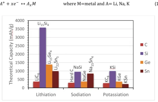
Concerning the anode materials used for LIB, NIB and KIB, the group 14 and 15 elements (Si, Ge, Sn, P, Sb, Bi) have been investigated (Table 2). Tin is electrochemically active with all three alkalis, forming Li22Sn5, Na15Sn4 and KSn corresponding to a theoretical capacity of 990, 847 and 226 mAh/g, respectively. [5,8,9] The obtained experimental capacities are lower (eg. 640, 655, 180 mAh/g for Li, Na and K, respectively[6]). Phosphorus forms Li3P, Na3P and K3-xP all with a theoretical capacity of 2596 mAh/g. [4,5,7] Antimony has a theoretical capacity of 660 mAh/g for Li (Li3Sb), Na (Na3Sb) and K (K3Sb). [8] Silicon displays a capacity of 4200 mAh/g for Li22Si5 and 3579 mAh/g for Li15Si4..[10,11] Theoretical studies have predicted the reaction of Si with Na and K with theoretical capacities of 954 mAh/g for NaSi [12] and 995 mAh/g for KSi[5]. In both cases the reaction suffers from poor kinetics and experimentally the c-Si has been considered to be inactive or at least partially inactive towards Na and K, however a-Si appears to be a potential candidate. [5,13–17]. Germanium, reacts with Li to form Li22Ge5 and Li15Ge4 with capacities of 1623[18] and 1384 mAh/g [19], respectively. The sodiation presents a theoretical capacity of 369 mAh/g, experimental values around 350 mAh/g corresponding to the formation of NaGe have been found. [9] The potassium insertion in Ge has a theoretical capacity of 369 mAh/g.[20] All the elements in this group suffer volume variations upon alloying reaction, in general with increasing alkali content and cation size the highest is the volume expansion.[3,5,6,8] This represents a critical issue to address before these materials can achieve practical commercial applications. Indeed the subsequent volume changes produces particle cracking, that upon repetitive cycling will lead to particles pulverization and detachment from the current
Relative atomic mass 6.94 23.00 39.10
Abundance on earth crust (wt%)
0.0017 2.6 2.4
Atomic density (g cm-3) 0.534 0.968 0.89
E0 versus SHE (V) -3.04 -2.71 -2.93
Theoretical capacity (mAh g-1) 3861 1166 685
Cost of industrial grade metal (US$/Ton)
collector. In addition the crack formation expose new electrode surface to the electrolyte, promoting a continuous and uncontrolled formation of Solid electrolyte interphase (SEI) on the particles and a high coulombic unefficiency. Several strategies have been proposed in the literature to address these challenges, including the electrode architecturing and nanostructuring, electrolyte formulation, use of composite electrodes and prelithiation processes, choice of binder, among others.
Table 2. Theoretical capacities of lithiation, sodiation and potassiation of group 14 and 15 elements and their approximated volume expansion after alloying reaction.
Material Alkali Stoichiometry
final product Theoretical Capacity (mAh/g) Approximated Volume change (%) Sn[5] Li Li22Sn5 990 676 Na Na15Sn4 847 420 K KSn 226 180 P[5] Li Li3P 2596 200 Na Na3P 2596 390 K K3-xP ≤2596 Not known KP 843 190 Sb[5] Li Li3Sb 660 147 Na Na3Sb 660 390 K K3Sb 660 407 Si[10–12,21,22] Li Li22Si5 4200 400 Li15Si4 3579 270 Na NaSi 954 114 K KSi 995 334 Ge[9,18–20,23] Li Li22Ge5 1623 370 Li15Ge4 1384 250 Na NaGe 369 225
K KGe 369 Not known
The challenges introduced by the use of Si- and Ge-based anodes for LIB, NIB and KIB require the understanding of the whole picture of the electrochemical processes taking place in the battery, which are too often neglected when designing new electrodes. In this review we begin by a revision of the electrochemical mechanism of Si and Ge in order to understand the
different phenomena related with the cycling. Following a short revision of the different strategies used for addressing capacity fading in Si and Ge electrodes is presented before introducing a new family of compounds, the so-called Zintl phases, which have potential applications as anode for LIB, NIB and KIB. In this last section the particularities and versatility of this family of compounds will be discussed, featuring their potential advantages over other conventional battery materials
2 Electrochemical mechanism insight
Both silicon and germanium are known to undergo an alloying reaction with Li, Na and K (Equation 1) that in most cases delivers higher theoretical capacities compared to the conventional carbon-based anodes. (
Figure 1). Nonetheless, it is accompanied by a huge volume expansion and particle pulverization that is detrimental for the electrode.
𝑀 + 𝑥𝐴++ 𝑥𝑒− ↔ 𝐴
𝑥𝑀 where M=metal and A= Li, Na, K (1)
Figure 1. Theoretical capacities of lithiation, sodiation and potassiation of C, Si, Ge, Sn. Adapted from ref. [5,24].
Before advancing in details into the electrochemical mechanism it is important to review the profile of the galvanostatic cycling of Si and Ge since the information they provide is crucial for the understanding of all the phenomena taking place during cycling.
Li
C
6 H ard C KC 8 Li15Si4 NaSi KSi Li15 Ge 4 N aGe KGeLi
22Sn
5Na
15Sn
4KSn
0 500 1000 1500 2000 2500 3000 3500 4000Lithiation
Sodiation
Potassiation
Th
eo
ret
ic
al
C
ap
aci
ty
(
mAh
/g
)
C
Si
Ge
Sn
2.1 Galvanostatic cycling of Si and Ge
The electrochemical behavior of silicon has been widely studied in the literature. The galvanostatic cycling of c-Si (Figure 2a), is characterized by a rapid decrease in the potential until reaching a plateau between 120 and 80 mV, then there is a change in slope close to the end of the discharge where the potential rapidly decreases. [25] During charge the processes take place at higher voltages, the potential increases rapidly until 0.4 V followed by a plateau, after which the slope increases upwardly suggesting a one-phase region. For the second discharge at least two different plateaus are observed. [25] These processes can be evidenced in the derivative curve (Figure 2b) by three reduction peaks and a very sharp oxidation one.
For nano-silicon (Figure 2-c), during the first discharge, the galvanostatic profile is the same as in bulk silicon. The main difference appears upon charge, where instead of a rapid increase in the voltage to 0.4 V followed by a plateau there is a gradual increase in the voltage. In the second discharge two plateaus appear in nano Si at 0.25 V and 0.10 V, indicating a different reaction compared to the first discharge. [26] Regarding the lithiation of amorphous silicon, initially it occurs at a higher potential compared to c-Si, but this potential decreases as the lithiation proceeds. In order to keep the lithiation in the amorphous region the cutoff voltage must be set before the crystallization of c-Li15Si4. [27]
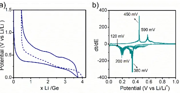
For the case of germanium (Figure 3), the electrochemical response presents four main processes during the lithiation. From 1.0 to 0.7 V the continuous drop in potential is attributed to partial reduction of the electrolyte leading to the formation of the solid electrolyte interphase (SEI) at the surface of the electrode.[28–30] From ≈380-250 mV and ≈250-150 mV, two pseudo-plateaus indicate the coexistence of two phases, and are followed by a drop of the potential (after ca. 200 mV), corresponding to a one-phase region. Upon delithiation, the slope increases abruptly until approximately 350 mV, followed by the presence of two pseudo-plateaus at 420-450 mV. The second lithiation is slightly different, the first pseudo-plateau (at
410 mV) presents a steeper slope, whereas the second (at 250 mV) is more marked. Both processes, however, occur at higher potentials, suggesting the electrochemical path followed during the second discharge is possibly different. All the processes in the galvanostatic curves are well defined in the derivative curves, except for the intensities of the peak at 590 mV during charge and the broadening of the peak at 380 mV during the second discharge indicative of a change in the nature of the Ge network compared to the pristine sample.
Figure 2. a) Galvanostatic curve of Si cycled vs Li, b) Cyclic voltammetry of Si vs Li with 0 V and 50 mV cut-off voltage, [31]c) Galvanostatic curve of nano- and bulk-Si vs Li and their respective derivative curves. [26]
Figure 3. Galvanostatic discharge-charge curves of the Ge electrode at a) C/5 and b) its corresponding derivative curve.
According to the literature the plateau during the first discharge is associated with the amorphization of the Si (Ge) into a-LixSi (a-LiGxe) intermediates, with the crystallization of c-Li15Si4 (Li15Ge4) at the end of discharge. These both phases are very similar, crystallize in the same space group I-43d and their lattice parameters differ in as little as 0.9%. [32] The delithiation proceeds with the amorphization of this crystalline Li15Si4 (Li15Ge4) phase and at the end of the process an amorphous Si (Ge) network is obtained. This last one can be affected by a series of factors like structure or residues of c-Si (c-Ge) in the electrode. The second and subsequent lithiation/delithiation of a-Si (a-Ge) are characterized by gently sloping profile indicating that the process occurs in the amorphous phase, then the energy differences between all the formed phases are smaller, the lithiation will occur preferentially on the previously lithiated regions. It is worth to note, that the formation of c-Li15Si4 has an impact over the profile of the galvanostatic and derivative curves, this is, if the cutoff voltage reaches values below 100 mV, the derivative curve displays a reduction peak at low voltages marked as C in Figure 2-b, while the delithiation is characterized by a plateau at 0.45 V and a sharp oxidation peak (F) in the derivative curve, the magnitude and the sharpness of the peak are measure of the presence of Li15Si4 at full lithiation. On the contrary, if the cell voltage is limited
to 100 mV (avoiding the process C), there is a change in the galvanostatic profile for the first charge where no clear plateau can be evidenced, characteristic of processes in the amorphous phase, and and the delithiation will be characterized by two broad peaks (D and E) (Figure 2-b). [25,33] The nature of these processes is not yet well understood and could be highly dependent on other factors such as dopants or structure of the Si. [31,33,34] The suppression of the formation of Li15Si4 has been observed at high C/rates due to a kinetic limitation to achieve full lithiation, translated into a decrease in the capacity [35] and for films of thicknesses lower than 500 nm. [36] Nevertheless, this last one is subject of debate, according to Obrovac [37] during the first 20 cycles of lithiation/delithiation of a Si thin film the profile of the derivative curve is similar to a-Si, but after continuous cycling the sharp peak near 0.42 V typical of the formation of Li15Si4 appears. Indeed, the formation of c-Li15Si4 is believed to be the responsible for the delamination of the Si films after certain cycles. [37]
Despite the similarities between Si and Ge their lithiation phase formation sequences, kinetics and mechanical responses are different. For instance, for Silicon the lithiation of the crystalline phase happens in an anisotropic way and is governed by the movement a two-phase boundary between the inner crystalline Si core and the outer amorphous LixSi alloys. Note that this is only applicable for the first cycle, after which the silicon remains amorphous. [38] The lithiation of a-Si is isotropic and leads as well to the formation of a-LixSi intermediates. [31,32] At the end of discharge, the spontaneous crystallization of Li15Si4 is not common in other alloy anodes, in which crystalline phases are attained via a two-phase reaction that implies nucleation and growth processes. For instance as the x value in a-LixSi approaches 3.75, the electronic structure of Li3.75Si becomes very similar to the Li15Si4, the phase transformation is possibly driven by the similarities of the electronic structures between the amorphous and the crystalline phases at high Li contents. This process only takes place electrochemically and no composition fluctuations are observed during the crystallization. The formation energies of Li15Si4 must be then lower than the amorphous counterparts and other crystalline phases with
similar composition like Li12Si7 and Li13Si4.Thus the lithiation mechanism of Si does not follow the thermodynamically stable phases in the phase diagram. [24,31,36]
The lithiation of germanium is isotropic; these difference compared to Si lies in the properties of the crystallographic planes of unlithiated Si (Ge) crystals that adjoin the amorphous product. This is, the orientation dependence of interfacial mobility at the sharp boundary of the two phases (pristine crystal and amorphous lithiated intermediates) is expected to govern the lithiation anisotropy in Si, rather than the long-range transport. While Si has a preferential lithiation the (110) planes, Ge does not experience such phenomena and lithiates evenly in all the directions without the formation of cracks during lithiation. These factors influence greatly the final electrochemical performance and in general an isotropic expansion is favoured in order to extend the lifetime of the battery. [31,39] In the case of germanium compared to silicon the Li diffusion is about 400 times faster [40] and the electronic conductivity is two orders of magnitude higher. [41] In parallel with Si, the lithiation happens from the surface of the particles to the core, with the cracks nucleating in the particle edges and propagating inwards. [39,42] During its lithiation the Ge-Ge bonds gradually break to form a-Li2.26Ge and later a-Li3.5Ge (like in the crystalline Li7Ge2). Both phases are constituted of Ge dumbbells and isolated Ge atoms, since these motifs are present in several LixGe phases with similar structures and formation energies the transformation might not be linear and several other intermediates could be involved. As the lithiation proceeds, the number of isolated Ge atoms increases and the
crystallization of
c-Li15Ge4 is energetically favoured. [18,43] Indeed, for Ge the nature of the formed phases depends on particles size and morphology and cycling conditions like C-rate or electrode formulation, these factors affect the kinetics of phase formation. [18,44,45]
2.2 Alloying mechanism
2.2.1 Lithiation
The understanding of the behavior of Si in a battery is crucial, but the phase diagram based on thermal processes does not necessarily represent the processes taking place in a battery. A typical phase diagram includes LiSi, Li12Si7, Li13Si4 and Li22Si5, all of them with less formation energy for the crystalline phases than for the amorphous one. However during lithiation no crystalline phases are formed despite their lower Gibbs free energy. The LixSi products are always amorphous with composition 0<x<3.75, at x=3.75 the crystallization of a phase takes place through a spontaneous process without long-distance atomic diffusion. For a long time this crystalline phase was presumed to be Li22Si5/Li21Si5[46,47] but in 2004 Obrovac[48] established it as Li15Si4 corresponding to the most lithiated phase formed electrochemically at room temperature while Li22Si5/Li21Si5 can only be obtained for very slow rate cycling at T°>100°C. [49,50] The Li15Si4 has lower formation energy than other alloys with the same Li content and it is metastable, decomposing rapidly into other lithiated compounds such as Li13Si4, Li7Si3 or other weakly crystallized phases. [31,51]
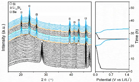
The in situ and ex situ XRD analysis (Figure 4) of the electrochemical lithiation mechanism of Si, indicates a gradual decrease in the diffraction peaks of c-Si upon lithiation, corresponding to the amorphization of the crystalline network. Following the system shows no diffraction peaks indicating the presence of amorphous phases, until 100 mV where a phase corresponding to Li15Si4 starts to crystallize, which below 50 mV is transformed into a non-stoichiometric phase c-Li15+δSi4.[34] All these processes are in line with the previous description of the plateau and peaks in the galvanostatic and derivative curves respectively for the first discharge. During charge, the diffraction peaks associated with c-Li15Si4 gradually disappear, in agreement with the plateau and peak at around 0.4 V in the galvanostatic and derivative curve, respectively, indicators of the amorphization of c-Li15Si4. At the end of charge an amorphous pattern is recorded. [33] The presence of amorphous silicon, influences the potentials at which the processes take place during the second discharge with the formation of a-LixSi intermediates at
higher potential values compared to the first discharge, while the crystallization of c-Li15Si4 happens at a slightly lower potential. [52][25]
Figure 4. In situ XRD for a self-supported Si electrode cycled vs Li at a rate of C/5.
Given the amorphous nature of the different lithiated intermediates in the Li-Si system, alternative studies such as NMR, XAS, Raman, among others, must be implemented in order to study the short-range order interactions and relate them with the electrochemistry phenomena. For instance Grey et al [41,53–55] have devoted great part of their studies to the identification of these intermediates, indeed the lithiation happened to be more complicated than previously thought and dependent on several factors. By studying the 7Li NMR, it is possible to identify different lithiated intermediates. The lithiation starts by the Si surface, the presence of Li in the Si framework eventually results in the breaking of the Si-Si bonds, with the loss of all the long range ordering in c-Si and the formation of small Si clusters. Given the large associated energy to break the crystalline Si network, once the lithiation has started and the small clusters are formed (stars, rings and dumbbells), it is kinetically easier to continue breaking these clusters than the original Si framework. Both processes compete and prevent the system to reach equilibrium. Due to the inhomogeneity of the processes, no single type of
cluster is present at this stage, hindering the crystallization of any phase as it will require bond breakage and rearrangement involving high activation energies. The breakage of the small clusters continues until the formation of mainly isolated Si ions, from which the c-Li15Si4 nucleates. The preference in the nucleation of c-Li15Si4 over Li22Si5 (a phase composed also of isolated Si ions), lies in the ability of the first one to accommodate defects such as the dumbbells that are presumed to remain at this stage. [34] Additionally the atomic arrangements of a-Li3.75Si and c-Li15Si4 are very similar, favoring the crystallization of this last one and no other phase. [36]
These phenomena originate characteristic Li environments that are related with the degree of lithiation (Figure 5). This is, as the Li/Si ratio increases the chemical shift moves to lower frequencies and the shielding around the Li ions increases: i) signals between 16-22 ppm are attributed to small Si clusters like in Li12Si7 (planar Si5 rings and Si4 stars), ii) signals between 12-14 ppm are attributed to Si dumbbells like in Li7Si3, iii) signals between 8-10 ppm describe lithium ions interacting with both dumbbells and isolated Si4-ions like in Li13Si4, iv) signals between 3-6 ppm describe Li interacting exclusively with isolated Si ions like in Li15Si4, v) signals between -1 to 3 ppm are attributed to Li species in the SEI layer. Finally signals with negative shift are attributed to the formation of the overlithiated phase Li15+δSi4. [34,56–58] This last one is only observed for the in situ experiments, and the negative shift suggest a more shielded environment. This resonance grows at the expense of the peaks with positive shifting, its intensity is enhanced by holding the voltages at 0 V but it rapidly disappears if the cell is relaxed, however no change in the macrostructure is detected at this stage. Li15Si4 is an electron deficient phase with high degree of defects, hence it can accommodate extra Li to form c-Li15+δSi4, since for the system it is more favored to further lithiate c-Li15Si4 than to convert the residual a-LixSi into c-Li15Si4 originating the negative shift in the NMR experiment. These results indicate that the lithiation process is inhomogeneous and is related to the different cycling conditions, defects, particle size, etc. [34,56–58] For instance an electrochemically
formed c-Li15+δSi4 phase from a pristine Si electrode presents a different 7Li NMR shift compared to the one obtained from mechanically synthesized c-Li15Si4 (discharged to 0V). [34,57] Finally the formation of c-Li15Si4 is incomplete, in some cases there are residual unbroken Si-Si pairs that limit the maximum of Li atoms that can be bonded to Si, explaining the inability of
the system to go towards higher
x values, x=4.2 or 4.4 like in Li21Si5 and Li22Si5 .[59]
On the other hand, if the cutoff voltage is set to 85 mV, at this stage there are more clusters than isolated Si ions. Hence, upon delithiation, these clusters serve as nucleation sites for the reconstruction of the amorphous network by the addition of isolated ions and/or the fusion of several small clusters. This is translated in a decrease in the signal of the 18-16 ppm peak after 300 mV. This peak shifts to lower frequencies close to 10 ppm at around 450 mV, indicating a depletion of small clusters due to a preferential delithiation while the isolated Si ions are still present in the system (like in Li13Si4). Beyond this point the 10 ppm resonance disappears and a new one appears at 3 ppm nearly at the end of charge. [34]
Figure 5. Ex Situ 7Li NMR MAS of batteries stopped at a selected potential during a) first discharge, b) first charge and c) second discharge. [34]
For Ge, few information is focused on the basic lithiation mechanism. [18,30,45,60–62] Some studies demonstrate that the Ge particles size and morphology have a strong impact on the lithiation mechanism and stabilized phases.[18,30,43,45,60–64] Indeed, in analogy with the lithiation of silicon, the XRD findings show amorphization of c-Ge upon lithiation, followed by the formation of amorphous lithiated intermediates and the crystallization of c-Li15Ge4 at the end of discharge while the charge happens almost completely in the amorphous phase. The results are, however, difficult to rationalize; even if it seems clear that crystalline Li15Ge4 and Li15+δGe4 are the end-products under electrochemical conditions, there is still no consensus on the different intermediated phases. Moreover, the presence of such intermediate phases depends strongly on the current density, revealing the importance of kinetics in the electrochemical mechanism.
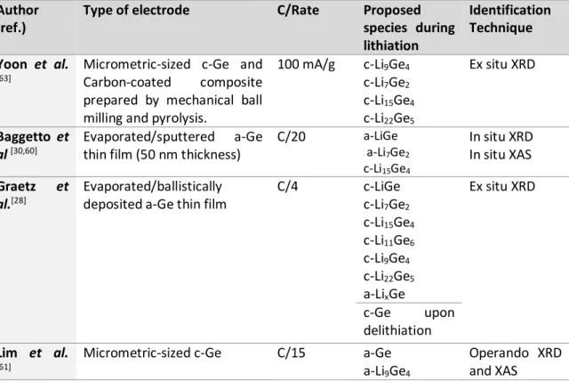
Table 3. Literature review of the chemical species formed during lithiation of germanium electrodes.
Author (ref.)
Type of electrode C/Rate Proposed
species during lithiation Identification Technique Yoon et al. [63]
Micrometric-sized c-Ge and Carbon-coated composite prepared by mechanical ball milling and pyrolysis.
100 mA/g c-Li9Ge4 c-Li7Ge2 c-Li15Ge4 c-Li22Ge5 Ex situ XRD Baggetto et al [30,60] Evaporated/sputtered a-Ge thin film (50 nm thickness)
C/20 a-LiGe a-Li7Ge2 c-Li15Ge4 In situ XRD In situ XAS Graetz et al.[28] Evaporated/ballistically deposited a-Ge thin film
C/4 c-LiGe c-Li7Ge2 c-Li15Ge4 c-Li11Ge6 c-Li9Ge4 c-Li22Ge5 a-LixGe Ex situ XRD c-Ge upon delithiation Lim et al. [61]
Micrometric-sized c-Ge C/15 a-Ge a-Li9Ge4
Operando XRD and XAS
a-LiGe a-Li7Ge2 a-LixGe c-Li15Ge4 Lim et al [45,62]
Micrometric-sized c-Ge >C/5 a-LixGe Operando XRD and XAS C/5<C<C/10 a-Ge a-LixGe a-Li9Ge4 c-Li15Ge4 C/20 a-LixGe c-Li15Ge4 Jung et al[18]
Micrometric-sized c-Ge C/50 c-Li7Ge3 a-Li7Ge2 a-Li13Ge5 c-Li15Ge4 c-Li15+δGe4 Ex situ XRD In situ/Ex situ Solid state NMR Pair Distribution Function Loaiza et al [44]
Micrometric-size c-Ge C/5-C/8 a-LiGe a-Li7Ge3
c-Li15Ge4
Operando XRD, XAS and Raman Spectroscopy. C/14 a-LixGe c-Li17Ge4 Tang et al [43] Ge Nanorods embedded in multiwall carbon nanotubes
C/5 a-Li2.26Ge a-Li3.5Ge c-Li15Ge4 c-Li15+δGe4 In situ XRD In situ Solid State NMR Morris et al[64] --- --- LiGe Li7Ge3 Li13Ge5 Li8Ge3 Li15Ge4 Li17Ge4 Density Functional Theory calculations
In analogy with Si, the information obtained by XRD is very limited and other characterization techniques are implemented. Table 3 shows some of the different intermediates and the respective characterization techniques used to identify. It is worth to note that Graetz et al. [28] have identified some of the lithiated intermediates by ex-situ XRD,
this point is particularly surprising given the fact that later reports identify most of the intermediates to be amorphous phases, hence, the presence of crystalline phases in this study might be related with the sample treatment before the XRD analysis, which given the metastable nature of the involved phases could induce to their crystallization. The XAS technique has been implemented commonly for the identification of the intermediates, and phases such as a-LiGe, a-Li7Ge2, a-Li7Ge3 and a-Li9Ge4 have been identified. These phases
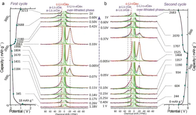
present very similar properties and their interpretation from the results could variate depending on the used method. It is concluded as well that one or more of the previous phases coexist at the same potential, thus the lithiation process is highly inhomogeneous. [44,60,61,65] The solid state NMR is another powerful technique to identify the different lithiated intermediates which in analogy to the findings for silicon have a characteristic signal at different frequencies. In this sense, signals between 20-25 ppm are attributed to phases with Ge dumbbells like in Li7Ge3 and Li9Ge4, with the formation of Li7Ge3 being more energetically favored. Signals between 12-14 ppm are attributed lithium ions interacting with both dumbbells and isolated Ge4- ions like in Li7Ge2 and Li13Ge4. Signals between 0-10 ppm describe Li interacting exclusively with isolated Ge atoms like in Li15Ge4, while the ones between 24 to -21 ppm featured a process of overlithiation of the Li15Ge4 into Li15+δGe4. This process of overlithiation is identified merely by means of NMR spectroscopy, where it is possible to observe the difference of the chemical shift of the phase due to a new Li environment that is more shielded. Other characterization techniques did not show any difference in the results at this voltage. Indeed the Li15Ge4 is an electron deficient phase and can accommodate extra charges without any change in the crystal structure, this is a purely electrochemical driven reaction that terminates once the cell is allowed to rest at OCV. [41,43]
Figure 6. Stacked in situ 7Li NMR of a Ge-carbon nanotube composite obtained during the a) first and b) second discharge/charge cycles. [43]
2.2.2 Sodiation.
The sodiation of silicon has been less investigated, whether crystalline Si is electrochemically inactive or at least partially is subject of debate, one can find reports supporting both statements. This reaction is considered to be impeded by the poor Na kinetics and the positive binding energy during the sodiation of c-Si. [12,13,66] Some authors have reported the sodiation of nano-sized c-Si, which after the first sodiation is transformed in a-Si, the following cycles take place in the amorphous domain. Micron-sized c-Si does not experience a sodiation process. [14,15] On the contrary, the sodiation of amorphous Si is possible. According to the Na-Si phase diagram the most sodiated phase has a composition 1:1, leading to a theoretical capacity of 954 mAh/g. [12] Recently a theoretical report showed that the maximum Na storage in Si is 0.76 Na, corresponding to a theoretical capacity of 725 mAh/g.[67] Experimentally it is not clear how many atoms of Na can be stored in Si, neither the achievable capacities or which dimensional scale or form (nano, micron, amorphous, crystalline) is required. [17] Reports in the literature have showed the feasibility of sodiation of a-Si, yet with severe transport limitations that can be partially improved by electrodes nanodesigning. [12,13].
In analogy with Si, the insertion of sodium in c-Ge is almost negligible. The major obstacle lies in the high diffusion barrier for Na in Ge lattice, due to its larger size the activation energy for migration between the interstitial sites in the lattice is higher (1.5eV for Na compared to 0.51eV for Li). [68] Still, c-Ge can be amorphised after the first discharge/charge cycle while the sodiation continues in the amorphous phase. [68]. Amorphous Ge is active towards sodiation, [20,69] the phase diagram indicates NaGe as the most sodiated phase, but recent reports have shown the insertion of more than one sodium in the Ge lattice, corresponding to Na1.6Ge. [68,70] In addition, GeOx has shown some activity vs Na, with the formation of Na2O that serves as a buffer to accommodate the volume changes during cycling. [71,72]
2.2.3 Potassiation
The knowledge regarding alloying compounds with potassium is limited. It has been theoretically predicted that Si undergoes this reaction to form KSi with 955 mAh/g. This process is expected to happen through a series of alloys, like K12Si17, K7Si46, K8Si46 and KSi. Crystalline silicon is believed to be inactive towards potassiation.[5] Yet, theoretical predictions indicate that amorphous Si can store up to 1.1 K-ion leading to a theoretical capacity of 1049 mAh/g, the K-ion can diffuse rapidly in the a-Si network, due to the weak electrostatic K-Si attraction and the formation of isolated Sin clusters during the potassiation. [22] Experimentally, few work has been performed, Sultana et al[5] reported the electrochemical inactivity of Si with K, whereas Komaba et al[6] presented in a preliminary study of the potassiation of a-Si with a capacity of 510 mAh/g. In the case of germanium, the crystalline phase shows no activity while the amorphous counterpart is expected to form KGe with a theoretical capacity of 369 mAh/g. Experimentally, a nanoporous Ge electrode has delivered a capacity of 120 mAh/g. [20]
3 Challenges and limitation in Si and Ge anodes
Whether the Si or Ge alloying reaction with alkali is anisotropic or isotropic they lead to volume expansion and particle pulverization. The lithiation of Silicon happens preferentially along the <110> direction with a swelling of ≈200% while the <111> direction experiences only
10%. In contrast, germanium has a more flexible lattice that undergoes facile atom rearrangements during lithiation. As a consequence, the volume expansion happens both in the axial and radial direction, resulting in a more uniform and faster lithiation and in a reduction of particle cracking. [32,73] For the sodiation and potassiation, given the inconsistencies with the maximum known values for alkali insertion in Si and Ge (NaSi[74], Na0.76Si[67], NaGe[69], Na1.6Ge[23]), the information regarding the nature and degree of volume expansion is limited, though it is known to be related with the quantity and size of inserted alkali. [3,5,6,8]
Indeed this volume expansion is one of the main challenges for the implementation of Si or Ge in commercial applications. The full lithiated states can expand up to 300%, compromising the stability of the electrode morphology by the formation of cracks and change in the connections with the conductive network. After delithiation, the particle contracts and is unable to return to its pristine state. With the constant expansion/contraction the particles suffer from cracking and pulverization that derive in a fracture/disconnection from the conductive network. [11] The pulverized or disconnected particles cannot participate in the electrochemical reaction leading to capacity fading. [75] Another limitation is the low initial coulombic efficiency due to the consumption of Li+ by the SEI formation during the first cycle, which contributes to the irreversible capacity and depletion of the Li reservoir in the cathode (for a full cell). Moreover the trapping of Li increases upon cycling due to the continuous formation of fresh surfaces in the alloying/dealloying process. To summarize the silicon/germanium electrode failure is due to :[10,11,76]
i) Large volume changes in bulky films and particles lead to high internal stress causing pulverization of the particles.
ii) Pulverization leads to detachment from the current collector and conductive network, causing isolation of the material, meaning that they no longer contribute to the energy delivered by the electrode.
iii) Unstable and uncontrollable growth of the SEI layer that increases the resistance of the electrode and irreversibly consumes Li. The expansion and contraction is continuously exposing fresh particle surface for the formation of new SEI layer.
Since the volume change cannot be avoided, the key solution is the improvement of the cyclability by preventing the loss of electrical contact between the electrode and the current collector and by stabilizing the SEI layer. Strategies to achieve this goal are the reducing of the operating voltage at the expense of the capacity and the use of composites and nanostructures.
3.1 Nanostructures
Limiting the particle size has been proven to be a good strategy to improve cyclability. Indeed, both silicon and germanium have a critical particle size after which the cracks appear. For crystalline silicon this value is limited to 150 nm[4,8] while for the a-Si and c-Ge due to their isotropic volume expansion these values are limited to 870 [31,77] and 620 nm [33,48], respectively. The use of nanostructures appears then as an efficient approach to improve the cyclability since i) their smaller size buffers the volume expansion and their unique architecture minimizes the stress along a specific orientation and avoids cracking or pulverization[11], ii) their high surface area maximizes electrochemical reactions in the electrode but also increases the amount of parasitic reactions [35], their interconnected electrolyte-filled network enables fast ion transport and their structure offers a directional path for fast electron transport. [78] Each type of architecture contributes in a different way to the electrochemical performance but has its own limitations, from here the interest of combining them in the electrode design. In the following segment we will revise the characteristics of the most common nanostructures.
Nanoparticles (NP): Their smaller size grants a lower associated volume expansion, higher specific surface area and tolerance to tensile stress and improved transport pathways for electrons and ions along the binders or conductive additives. All of these conditions minimize the electrode degradation and improve the cycling performance.[38,75,76,79] Nevertheless, the cycling stability is restricted by the limited space to accommodate volume changes, undesirable reactions and excessive formation of SEI in their surfaces. [79] In addition, with repeated cycling the NP tend to merge into bigger particles, leading to a decrease in the surface to volume ratio and eventual peeling from the current collector. [31,80]
1D structures: They distribute the volume expansion along the radial direction, in order to minimize particle cracking and the abundant empty space between the structures serves as a buffer for volume changes. Along the length direction they provide efficient electron transport and intimate contact with the current collector, allowing rapid charge transfer. However their synthesis methods are complicated and expensive, hindering their implementation at large scale. [10,38,75,81,82] Examples of these type of structures are the nanowires (NW), which can be grown directly in the current collector eliminating the need for conductive additive or binders. Unfortunately, the NW still can be broken and expose surface to the formation of new SEI layer that will thicken with repetitive cycling limiting the Li+ transfer. [76] Hence, there is a critical diameter (<300 nm) in order to obtain the best performance in terms of coulombic efficiency and cycle life. [80,83] The nanowires can be added as active material in a composite containing the binder and the conductive additive, often they result in flexible and robust structures. [11] The nanotubes (NT) compared to NW and nanofibers usually bear much higher specific surface area when they possess a hollow structure. This last one helps to buffer the volume expansion, allowing it to be released inward and outward. [11] Since the outer and inner parts are exposed to the electrolyte, the diffusion paths for the ions are shorter, but an excessive formation of SEI layer is promoted. [81] The length, outer and inner diameters and the
wall thickness are important parameters that determine the electrochemical performance of the NT. [80]
2D structures: In order to avoid the particle rearrangement due to volume expansion the initial film should have enough void space (interparticle space) to accommodate the changes. [10] The film thickness has an impact on the electrochemical performance and in general thinner films perform better due to a better conductivity due to a shorter distance to the current collector.[11] For these factors the thin films have limited mass loading and thickness and are only foreseen for microbatteries.[75,80,81] Note that films with thicknesses lower than 2.5µm do not form Li15Si4. [80] Another 2D structures are the nanosheets (NS), due to their low dimensionality they provide fast kinetics for ion transport and buffer the strain generated by the expansion/contraction process. Their large surface area allows an effective contact between the electrolyte and the electrode.[81]
Micron-sized Si(Ge). Despite the advantages of nanostructures to buffer the volumetric expansion, they depict complex synthesis methods, low mass loading and low coulombic efficiency. Hence it is practical to engineer micrometer silicon with characteristics of the nano-sized one. [10] With this approach, the tap density can be increased and as a consequence the volumetric energy. [38] This strategy can be implemented either by the introduction of nanopores/nanograins or by the incorporation of nano/micro-meter Si(Ge) in a micrometer host such as graphite or other carbon frameworks. [11,82] The pores diminish particle pulverization, serve as buffer for volume changes and facilitate the electrolyte diffusion in the structure; while the composites containing carbon benefit from a better structural stability, enhanced conductivity and stabilization of the SEI layer. [11,75,79]
Prelithiation: The high surface area of nanoparticles decreases the coulombic efficiency during the first cycle due to irreversible consumption of Li in the formation of the SEI layer, this process depletes the Li reservoirs in the cathode (for a full cell). With the prelithiation an
artificial SEI layer is created that is activated upon contact with the electrolyte, reducing the consumption of Li during the first cycle. [38] This process can be performed in three ways; electrochemically by contacting lithium foil with electrolyte-wetted anodes, mechanically by mixing the Si(Ge) with lithium metal powder and chemically by the synthesis of LixSi (LixGe) nanoparticles that are mixed with the rest of the slurry. [10,82]
Composites: Since it is challenging to tackle all of the Si(Ge) drawbacks by solely morphology control, the design of effective networks is vital for this purpose. The Si(Ge)/core carbon shell, is an interesting structure, in which the void space between the Si(Ge) core and the carbon shell, accommodates the volume changes without deterioration while the SEI layer is stabilized in the surface of the shell. A porous but rigid shell allows to keep the integrity of the conductive network without particle disconnection and provides an active Li+ diffusion path and efficient electron transport [10,38,75]. Tough, in some cases the volume expansion of the core affects the shell. Hence, the following factors must be considered for an effective design: i) the size of the core (less than 100 nm, to avoid excessive volume expansion), ii) the material of shell should be conductive and electrochemically stable, iii) the synthesis conditions should lead to an uniform, mechanically stable and conductive shell. [38] Ideally the shell should be thick enough to provide good mechanical and chemical stability but thin enough to avoid high ionic or electronic resistance. A similar structure is the Yolk-Shell in which the void space is engineered specifically to buffer volume expansion. [31,38,80]
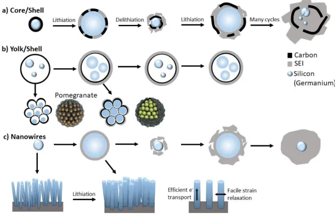
Figure 7. Solutions for fundamental problem of Si(Ge) anodes. Volume expansion and contraction of a)Core/shell, b) Yolk shell and the pomegranate assembly and c) Nanowires during lithiation and delithiation. The continued cycling leads to an uncontrolled growth of SEI layer in the core/shell and nanowires while the yolk/shell-type structures are able to stabilize a uniform SEI layer. Adapted from [10,79]
Silicon-graphite composites: This composite presents a remarkable improvement compared to graphite with good cycling stability and low cost of fabrication. The synergy between Si and graphite increases the capacity and improves the electrical conductivity and stabilizes the SEI layer. Note that the ratio between both components is critical in the electrode design to ensure the benefits from both materials. [11]
Silicon-graphene: In this composite the Si particles are deposited in between the layers of graphene which can deform easily to accommodate the volume expansion. The graphene layers that are far away from Si particles can reconstruct the graphite network due to van der Waals forces.[76] This method presents good mechanical stability and prevents the Si particles to be disconnected from the conducting network; it allows as well the preparation of free
standing electrodes. [11,76,79,80] However, since NP tend to aggregate, selecting the ideal matrix that can provide flexibility, high surface area and efficient electron and ion transport is important. [79]
Figure 8. Schematic of a Silicon/Graphene composite. Adapted from ref.[84]
Metal alloys: the use of metal alloys is another alternative to benefit from the desired properties of two or more elements. A very interesting composite is the Si-Ge alloy. Since Ge exhibits a series of advantages over Si, such as faster Li+ diffusion, higher electronic conductivity and lower volumetric expansion; the enrichment with Ge affects the rate capability and allows a better capacity retention.[85,86] Sn has also demonstrated to contribute to improve the capacity retention of a Si electrode. [87]
It is worth to note that most of these approaches are implemented as well for NIB, but despite the similarities between Li and Na, certain functions used for LIB may not work for NIB, because of the different kinetic limitations between the two systems. [78] Certain examples include the c-Si core/ a-Sishell composite, in which the c-Si core improves the electronic conductivity whereas the sodium storage occurs in the a-Si shell. [17] A porous Si-sponge, in which the synergy between the porous and the amorphous character helps to alleviate the volume expansion and improve Na kinetics, allowing cycling at high C/rates. [12] a-Si nano-membranes with enhanced Na+ transport kinetics is able to store Na through a pseudocapacitive/bulk mechanism. [66] A silicon/graphene and silicon graphite composite alleviates the Na transport limitation issues and improves the electronic conductivity. [88,89] Ge
nano-columns improve Na kinetics due to their short diffusion length. [90] a-Ge NP supported in Ni nano-pyramids with enhanced cycling stability and rate capability, due to enough space between each pyramid to buffer the volume changes and the intimate contact between Ni and Ge that shorten the diffusion paths. [68] The use of a-Ge thin film or porous c-Ge NP in which all the sodiation products are amorphous. [68,91,92] Finally the Li activation of Ge NWs, induces amorphization and porosity in the structure, reducing the barrier for nucleation of the NaxGe phase and accelerates the solid state Na diffusion. [29] Indeed a-Ge NW can store up to 1.6 Na per Ge (Na1.6Ge) due to the high concentration of defects in a-Ge. [23]
Table 4. Electrochemical performance of some Si anodes for LIB and NIB. Adapted from refs. [11,17,75,82]
Type of Si(Ge) Cycling stability
Specific capacity (mAh g-1)
Cycle number Current/rate
LIB Nanosized Si (Ge) Si Nanoparticles 1180 500 3 Ag-1 Ge Nanoparticles 1100 100 C/10 Hollow Si 1420 700 C/2 Porous Si 1200 600 C/2 Si Nanowire 3500 20 C/5 Ge Nanowire 1000 20 C/20 Si Nanofiber 1821 1000 C/5 Si Nanotube 2000 50 C/5 Ge Nanotube 1002 50 C/5 Si nanofilm 3000 1000 12C Micrometer Si (Ge) 3D porous Si 2800 100 1C Pomegranate-like Si 1160 1000 C/2 Si (Ge)/C composites Simple Ge/C 700 50 0.15 Ag-1 Simple Si/C 1200 30 C/10 Core-shell Si/C 1490 1000 C/4 Yolk-shell Si/C 1500 1000 1C Si/graphene 840 300 1.4 A g-1 Ge/graphene NW 1059 200 4C Other composites Si/conductive polymer 550 5000 6 A g-1 Si-Ge alloy 1600 50 2C NIB
(Ge) Nanoparticle cycle) (248 mAh g-1) a-Si thin film 600 (after 1st
cycle) 100 (240 mAhg-1) C/10 Si(Ge)/C composite
Si/C fiber 283 (after 1st cycle)
200 (298 mAh g-1)
50 mA g-1
3.2 Electrolyte formulation and additives
In addition to the electrode architecture and composition, other features have to be considered to improve the performance of Si (Ge) anodes. One of them is the electrolyte formulation since it is related to the formation of the SEI layer that is expected to inhibit further side electrochemical reactions on the surface of the electrodes and to guarantee a good cycle life via effective ion transport. [75] However, the alloying reaction promotes a continuous and excessive SEI formation due to its facile detachment from the particles surface during the expansion/contraction process and the particle cracking that exposes new surface area. This uncontrolled growth of SEI layer impedes the transport of ions and increases the resistance of the electrode. [75] In general the stability of the SEI layer depends on the choice of salts, solvents and additives. [76] The SEI layer derived from carbonate solvents is composed of polymeric and oligomeric organic units and it is semipermeable to the electrolyte components, meaning that it is continuously decomposed with little passivation effect. [11,76].
Hence, an efficient approach to stabilize this SEI layer is the use of additives, which most of the times are designed to be consumed during the initial formation the SEI layer, but can serve also to improve the electrochemical stability window of the electrolyte, or to enhance the safety (flame retardants). [93] Common additives include vinyl carbonate (VC), fluoroethylene carbonate (FEC) or Lithium bis(oxalate)borate (LiBOB). [11,81] Both FEC and VC reduce before the carbonates providing an initial protective layer on the particle surface. VC decomposes into polycarbonates at about 1 V vs Li/Li+, the presence of double bonds in its structure rend it is more susceptible to reduction. [11,94] FEC decomposes at 1.3 V vs Li/Li+ into a passivating layer that is much more compact resulting in a lower mass transfer resistance and improved
capacity retention. [3,11,93] FEC decomposes into polyenes and a high concentration of Li2O which prevents the diffusion of HF through the SEI. [93] It promotes the formation of Li-F and F (Ge-F) bonds that are much stronger and give more stability to the SEI layer, compared to Si-C (Ge-Si-C) or Si-O (Ge-O) bonds that are constantly decomposing and reforming if there is no additive. However, if FEC is used in excessive quantities, the formation of HF and LiF is boosted, causing cathode dissolution, consumption of Li reservoirs and increase of the irreversible capacity. [10,11,94] It is crucial then to optimize the additive content and to use mixtures (VC+FEC) with synergetic effects that impact the electrode performance. [94].
For Sodium and potassium, given their different reactivity with the electrolyte solvents, the composition of the SEI layer differs from their Li analogue. For Na a lower quantity of oxygenated or organic species is found, being mainly composed of Na2CO3 and alkyl carbonates ROCO2. Since the Lewis acidity of Na is lower than Li, the coulombic interaction of Na+ ions with negatively charged species or lone pairs is weaker, as a result the solubility of the electrolyte decomposition products is higher for NIB. [3,95–97] Therefore the use of additives is crucial to avoid further SEI dissolution and electrolyte decomposition. [3,98] For potassium, certain electrolytes are suitable for the anode but not for the cathode, due to composition of the SEI layer on top of the K surface (for half cells). For most of the anodes the KFSI salt has been found to be the most stable. The carbonate based solvents allow reversible cycling whereas the glymes-based present systematic failure. [99] Whether the additives improve the performance or not is not clear yet [5]. In any case, in order to avoid undesired reactions of K with the electrolyte, full cell test must be implemented. [99]
3.3 Binder
The role of the binder is to keep all the particles together, attach them to the current collector and alleviate the stress induced during volume changes maintaining the mechanical stability of the whole electrode. Polyvinyldene fluoride (PVDF) is one of the most common binders for different technologies, but due to the lack of polar functional groups it only offers weak van
der Waals interactions that are not sufficient to maintain the integrity of the electrode. [11,76,81] On the contrary other binders such Carboxymethyl cellulose (CMC), poly acrylic acid (PAA) or Sodium alginate contain polar groups that interact strongly with the hydroxide groups on the particle surface via hydrogen or covalent bonding, improving the adhesion. [100,101] These binders are soluble in water, meaning that the slurry can be prepared in aqueous media, which is more environmentally friendly compared to PVDF processing in N-Methyl-2-pyrrolidone (NMP). [11,76,80,81] Nonetheless, during the volume expansion process the integrity of the binder can be compromised. The polymer chains can slide, isolating the active material particles from the conductive network, a chain crosslinking can address this issue. [81] In this sense, the use of self-healing binders is of great interest since they can repair spontaneously the mechanically destruction of the electrode, thanks to the re-association of hydrogen bonds.[10] Another concept is the use of conductive binders that ensure the electrical connectivity of all the particles even after the particle pulverization due to volume changes. [31] (Figure 9)
Finally, in order to improve the contact between the current collector and the active material to decrease the electrical resistance and improve the cycle life, a porous or rough treatment by sandpaper and chemical or electrochemical etching of the current collector is suggested. [81]
For further reading about the challenges and strategies for the implementation Si and Ge anodes reader can be referred to [10,11,31,38,81,82]
Figure 9. Schematic of a Si electrode with non-conductive binder (e.g. PVDF) and conductive additive (e.g. Carbon black) and with conductive polymer with dual functionality as conductor
and binder. Adapted from ref. [102]. b) Capacity vs cycle number for a Silicon anode with different types of binder. [103]
4 Zintl Phases
This family of compounds have been known for a long time, but their applications in batteries are very recent. The following section comprises an extensive explanation of the nature, properties, versatility and application of the Zintl phases.
4.1 The Zintl-Klemm Formalism
The Zintl phases are named after Eduard Zintl who in 1929 studied a family of compounds in which one component is a highly electropositive material and the other is an element located in the right side of the so-called the Zintl boarder; today known as semimetals, metametals or metalloids. [104] (Figure 10) In Zintl phases the valence electrons are formally transferred from the electropositive to the more electronegative component, the anions do not achieve an electronic octet rule as isolated species but may rather bond to each other, forming cationic and anionic frameworks. The versatility of the Zintl phases arises from the characteristics and interactions between these frameworks, resulting in an enormous variety of crystal structures, ranging from cluster compounds to extended solids, in which certain physical and chemical properties can be tuned. [105,106]
Figure 10. Periodic Table showing the Zintl border according to Zintl (red) and to Klemm (blue).[107]
Zintl defined some rules in order to distinguish the Zintl phases from intermetallics. A Zintl phase should; [105]
i) Contain an alkali, alkaline-earth metal or p-element that is a metal, semimetal or small bandgap semiconductor.
ii) Have electrochemically balanced or closed-shell compounds, meaning that the number of electrons provided by the constituting elements is equal to the number of electrons needed to form a covalent bond.
iii) Have a well-defined relationship between the chemical (geometrical) and the electronic structure.
iv) Be semiconductors (band gap < 2eV) or poor conductors.
v) Show diamagnetism or weak temperature dependent paramagnetism (Pauli paramagnetism).
vi) Be brittle
Since a vast number of compounds that do not follow all the Zintl rules, during the course of the years the definition of Zintl phases has changed and adapted. Wilhelm Klemm extended the Zintl concept through the pseudoatom approach in which he studied isoelectronic Zintl anions. This is, after receiving the electrons from the electropositive metal, the electronegative will behave like the isoelectronic neutral atom at its right. [105] In 1980 Von Schnering extended the Zintl-Klemm concept from an 8N rule to a 18 e- one, not only to allow the study of transition metal compounds but also to prove that in some phases both concepts can work simultaneously. [104] Additional extension of the Zintl Klemm formalism have been proposed by Miller, Mooser and Pearson [108], Corbett [109,110], Van der Lugt [111] and Nesper [104,107,112] and Belin [113].
Since the discovery of the Zintl phases, several compounds have been successfully synthesized and characterized.
4.2 Structural diversity of Zintl phases
The huge structural variety of Zintl phases is determined by the size and interactions of cations and anions. In other words, different structures varying from 0D clusters, 1D wires to 2D layers can be obtained from the same anion by changing the stoichiometry or the cation size. For example, in layered CaSi2 each Si is bonded to other three Si atoms, giving 4 + 3 valence electrons and the octet rule is completed by the electron donated from the Ca. This structure is analogous to the 3D bulk Si, but all the bonds along the [111] direction have been replaced by Ca2+ cations. If the stoichiometry is changed to CaSi, then each Si is bonded to only two Si atoms, forming zig-zag wires, here each Si atom has 4+2 valence electrons and the octet rule is competed by 2 electrons from the Ca2+. If the Ca2+ is replaced by a monovalent cation, like in KSi, NaSi, each Si atom is bonded to other three Si atoms forming isolated [Si4]4- tetrahedra, this gives 4+3 valence electrons, and the octet rule is completed by one electron from the cation. Figure 1111 [114] This tetrahedral unit (X4)4- similar to P4 and As4 and can be found in alloys of Si, Ge, Sn, Pb (M) with Na, K, Rb, Cs but not for Li. This effect is related to the size of the cation, as the size increases the metal atoms are more separated one from each other, reducing their interactions, compared to a LixM mixture, and in order to decrease their mutual distances and bond energies, they prefer to cluster together. [111]
Other type of Zintl phases are the cage-like clathrates, composed of tetravalent group 14 (Si, Ge, Sn and their mixtures) and trivalent group 13 elements as host structure. The guest atom (electropositive metal) is located in the cavities of the network and balances the electron deficiency by the formal charge transfer. The most common types of clathrate are Type I with the formula A8E46 and Type II with A24E136.[115] Another type of structures are the allotropes, composed of different arrangements of the same element that determine the specific properties of the material, examples are the allo-Ge and allo-Si. The first one is obtained from oxidation of Li7Ge12, a phase with two dimensional polyanionic [Ge12]7- separated by Li atoms. The second one from Li3NaSi6 which has polyanionic layers of [Si6]4- separated by Li and Na
atoms. In both cases the alkali is extracted while preserving the anionic structure. [116] These structural versatility opens a field of study, since the material properties can be changed in function of the desired application (optoelectronics, spintronic, magnetic, catalytic activity, etc.)[114].
Figure 11. Structural models for CaSi2 (layers), CaSi (wires) and NaSi (isolated tetrahedra).
4.2.1 Binary Zintl phases
LixM (M=Si, Ge): Lithium based Zintl phases present different characteristics compared to the
heavier alkali metal homologues, even with the same stoichiometry they exhibit completely different structures. The main reason is the Li high electron affinity, strong polarizing power and smaller size, which condensate the Zintl anions around the Li+. [107] For example, the LiM (1:1) consists of infinite [X-] linkages while the Na, K, Rb, Cs analogues ideally form X4 4-tetrahedra. Interestingly, the lithiated compounds with group 14 elements are mostly isotypic, meaning that Si can be replaced by Ge up to some extent. [107] Most of the Li-Si and Li-Ge phases do not follow the Zintl-Klemm concept. Both Si and Ge are not electronegative enough to completely strip all the Li atoms of their electrons and the charge transfer is not complete. At low lithium contents the compounds behave like Zintl phases but as the Li ratio increases the standard electron counting rules fails. [107,117] Examples of compounds that do not follow the electron counting rules are almost all lithium silicides and germanides, Li12Si7, Li13Si4, Li21Si5, Li12Ge7, Li9Ge4, Li13Ge4, Li14Ge4 and Li21Ge5 except the Li7Ge12, LiGe and LiSi. The electronic structure of all these compounds can be understood if the concept of an additional electronic state corresponding to a cage orbital is used. A cage orbital corresponds to metal (Li) electronic
![Table 1. Comparison critical parameters Li, Na and K-ion. Adapted from ref. [7]](https://thumb-eu.123doks.com/thumbv2/123doknet/11497815.293442/4.892.125.825.964.1157/table-comparison-critical-parameters-li-na-adapted-from.webp)

![Figure 2. a) Galvanostatic curve of Si cycled vs Li, b) Cyclic voltammetry of Si vs Li with 0 V and 50 mV cut-off voltage, [31] c) Galvanostatic curve of nano- and bulk-Si vs Li and their respective derivative curves](https://thumb-eu.123doks.com/thumbv2/123doknet/11497815.293442/9.892.198.693.402.801/figure-galvanostatic-cyclic-voltammetry-voltage-galvanostatic-respective-derivative.webp)
![Figure 8. Schematic of a Silicon/Graphene composite. Adapted from ref. [84]](https://thumb-eu.123doks.com/thumbv2/123doknet/11497815.293442/28.892.145.574.261.414/figure-schematic-silicon-graphene-composite-adapted-ref.webp)
