HAL Id: tel-01665012
https://tel.archives-ouvertes.fr/tel-01665012
Submitted on 15 Dec 2017HAL is a multi-disciplinary open access archive for the deposit and dissemination of sci-entific research documents, whether they are pub-lished or not. The documents may come from teaching and research institutions in France or abroad, or from public or private research centers.
L’archive ouverte pluridisciplinaire HAL, est destinée au dépôt et à la diffusion de documents scientifiques de niveau recherche, publiés ou non, émanant des établissements d’enseignement et de recherche français ou étrangers, des laboratoires publics ou privés.
atherosclerotic plaque adhesion strength and its role in
plaque rupture
Bilal Merei
To cite this version:
Bilal Merei. atherosclerotic plaque adhesion strength and its role in plaque rupture. Other. Université de Lyon; University of South Carolina, 2016. English. �NNT : 2016LYSEM016�. �tel-01665012�
N°d’ordre NNT : 2016LYSEM016
THESE de DOCTORAT DE L’UNIVERSITE DE LYON
opérée au sein deMINES Saint-Etienne
délivrée en partenariat international avec ‘University of South Carolina’
Ecole Doctorale N° 488
Sciences, Ingénierie, Santé
Spécialité de doctorat :
Discipline : Mécanique et ingénierie
Soutenue à huis clos le 29/09/2016, par :
Bilal Merei
Force d’adhésion des plaques
athérosclérotiques et son rôle dans leur
détachement
Devant le jury composé de :
Ohayon, Jacques Professeur Université de Savoie Président et
Rapporteur
Shazly, Tarek Professeur University of South Carolina Rapporteur Avril, Stéphane Professeur EMSE-CIS Directeur Lessner, Susane Professeur USC-School of medecine Directrice Sutton, Mickael Professeur University of South Carolina Co-directeur
A
THEROSCLEROTICP
LAQUEA
DHESIONS
TRENGTH AND ITSR
OLE INP
LAQUER
UPTUREby Bilal MEREI
Mechanical Engineer & Master in Science and technologies for health Lebanese University Faculty of Engineering, UTC France, 2010
Master of Biomechanics
Ecole des Arts et Metiers ParisTech, 2011
Submitted in Partial Fulfillment of the Requirements For the Degree of Doctor of Philosophy in
Biomedical Engineering
College of Engineering and Computing University of South Carolina
2016 Accepted by:
Stephane Avril, Major Professor Susan M. Lessner, Major Professor Michael A. Sutton, Committee Member
Pierre Badel, Committee Member
iv
© Copyright by Bilal Merei, 2016 All Rights Reserved.
ACKNOWLEDGEMENTS
I would like to gratefully and sincerely thank Dr. Stephane Avril for his guidance, understanding, patience, and most importantly, his friendship during my graduate studies at Ecole des Mines de Saint Etienne. His mentorship was paramount in providing a well-rounded experience consistent my long-term career goals. Also, I would like to thank Dr. susan Lessner from USC for her guidance and her help in every detail when I was in Columbia. I was lucky also to meet and work with Dr. Mickael Sutton who enriched my research experience, thanks to his advanced knowledge in the field of fracture mechanics. The work could not be done without Dr. Pierre Badel contributions, thank you for always giving me right advices when I needed and for the help in different topics.
I had the chance to be in a joint program and be in two cities during my Phd. This was not always easy but some great people and colleagues made life simpler. I would like to thank both laboratories in EMSE and USC. To my colleagues Moe, Lindsey, Alexandre, Baptiste, Rebecca, Pierre Yves, Nico, Aron, Fanny, Fanette, Shana and many others, it was a great experience with you. Special thanks to Sareh and Amelie from EMSE for all the support they gave to me and their priceless contributions. Even if we didn’t work directly together, but I was also lucky to meet and share my experience with Dr. Shazly and Dr. Eberth from USC, and get many constitutive advices from them.
vi
Obviously being surrounded by friends is the best feeling to give all the motivation you need. Thank you Chaker, my dearest friend, for giving me all the moral support I needed for more than 20 years. Thank you Katerina, my adorable friend, for being a part of this dissertation with all your effort to help in every single detail, you are amazing, and yes ‘tu es la meilleure’. To Youssef, Leonardo, Laeticia, thank you for all the encouragements. Special thanks to Katie, Dwain, and Cole, I couldn’t picture my stay in the US without you.
And finally, thank you my family, my brother, my sisters, my 12 nephews, and sure my father and mother. You are my first motivation for success and I hope you are proud of me.
FRENCH ABSTRACT
Les maladies cardio-vasculaires sont des maladies qui affectent les vaisseaux sanguins et le cœur. Selon l'Organisation mondiale de la santé, les maladies cardiovasculaires sont l'une des principales causes de décès dans le monde entier. Elles sont responsables de plus de 17,1 millions de décès par an dans le monde, ce qui représente 31,5% des décès 1, 2. L’athérosclérose, connue par un trouble inflammatoire chronique affectant les grandes artères, est la cause sous-jacente de nombreuses maladies cardio-vasculaires. La rupture de la plaque athérosclérotique est une complication grave de l'athérosclérose avancée, qui conduit souvent à des conséquences cliniques potentiellement mortelles telles que l'infarctus du myocarde (crise cardiaque) ou un AVC. Plus que 75% des cas d'infarctus du myocarde nouvellement développés sont causés par la rupture de plaque. Elle touche environ 1,1 million de personnes aux Etats-Unis par an, avec un taux de létalité de 40%; 220.000 de ces décès surviennent sans hospitalisation. Au cours des dernières décennies, les mécanismes de la progression de la plaque d'athérome et de formation ont été largement étudiés. Toutefois, en raison de la complexité des processus, les mécanismes de rupture de la plaque sont encore mal connus.
Dans cette thèse, une nouvelle hypothèse concernant les mécanismes de rupture de plaque est proposée. Plus précisément, nous supposons que la force d'adhérence de la liaison entre la plaque et la paroi vasculaire est un déterminant important de la stabilité de
viii
la plaque athérosclérotique (résistance à la rupture). Nous nous attendons également à ce que la force d'adhésion soit fonction de la composition de la plaque et de la matrice extracellulaire (ECM) à l'interface plaque-support. Ce mode de rupture proposé est appelé délaminage.
Les essais de délaminage de plaques de souris sont compliqués et ils nécessitaient plus de temps pour être exécutés et validés. Ainsi, en raison de la similitude du protocole expérimental, nous avons utilisé des données expérimentales obtenues sur la dissection de spécimens des artères coronaires humaines par Wang et al. 20143, et nous avons créé un modèle numérique pour appliquer la technique des éléments cohésifs à ce problème. La dissection artérielle est une maladie rare mais potentiellement mortelle dans laquelle le sang passe à travers la paroi interne et entre les couches de la paroi artérielle. Elle se traduit par une séparation des différentes couches, créant ainsi une fausse lumière dans le processus. Les avantages pour la réalisation d'une étude primaire sur la dissection artérielle ont été déterminants pour décider d’appliquer les modèles de zone cohésive à un problème moins complexe que l'athérosclérose.
Expérimentalement, l'approche technique innovante pour mesurer la force d'adhésion développée précédemment4,3 sera appliquée dans cette thèse sur des souris de deux génotypes différents. Notre équipe à l'USC, a été la première à effectuer ce type de mesures sur des souris. L'utilisation de souris dans nos expériences, présente l'avantage que la composition de la matrice extracellulaire pourrait être systématiquement modifiée
en utilisant des souches transgéniques, le régime alimentaire modifié, ou des traitements médicamenteux. Différentes souches de souris ou modèles pourraient alors être utilisées et les propriétés mécaniques seront étudiées sur chaque type.
Une autre innovation de notre travail implique l'application d'un modèle de zone cohésive pour décrire le comportement de délaminage des plaques athérosclérotiques dans une gamme de conditions physiologiques et physiopathologiques, en utilisant un modèle numérique 2D. Bien que l'approche de la zone cohésive soit largement utilisée pour modéliser les mécanismes de rupture dans les matériaux d'ingénierie classiques, elle est peu utilisée pour décrire le délaminage des plaques. L’étude qui a traité le délaminage par Leng et al. 20155 avait pour objectif de tester l’utilisation de zones cohésives en implémentant une loi de traction séparation spécifique, en assumant des valeurs de paramètres des lois de comportement de la plaque et de la zone cohésive. L’innovation dans notre approche est d’utiliser un schéma explicite et une loi de traction séparation simple pour étudier le comportement des plaques et identifier leurs propriétés. Les données expérimentales de délaminage des plaques seront utilisées dans la définition des lois traction-séparation de la zone cohésive.
MOTS-CLÉS: Maladies cardiovasculaires - dissection artérielle - plaque athérosclérotique - Modes de délamination - Mécanique de Rupture – Modèle à zone cohésive - Méthode Inverse
x
ENGLISH ABSTRACT
Cardiovascular diseases are disorders affecting the blood vessels and the heart. According to the World Health Organization, cardiovascular diseases are one of the leading causes of death worldwide. They are responsible for over 17.1 million deaths per year worldwide, representing 31.5% of deaths 1, 2. Atherosclerosis, a chronic inflammatory disorder affecting large arteries, is the underlying cause of many cardiovascular diseases. Plaque rupture is a serious complication of advanced atherosclerosis, often leading to life-threatening clinical consequences such as myocardial infarction (heart attack) or stroke. 75% of newly developed myocardial infarction cases are caused by atherosclerotic plaque rupture. It affects approximately 1.1 million people in the USA per year, with a 40% fatality rate; 220,000 of these deaths occur without hospitalization. Over the past few decades, the mechanisms of atherosclerotic plaque progression and formation have been widely studied. However, due to the complexity of the process, plaque rupture mechanisms are still poorly understood.
In this thesis, a novel hypothesis regarding mechanisms of plaque rupture is proposed. Specifically, we hypothesize that the adhesive strength of the bond between the plaque and the vascular wall is an important determinant of atherosclerotic plaque stability (resistance to rupture). We also expect adhesive strength to be a function of plaque composition and extracellular matrix (ECM) organization at the plaque-media interface. This proposed mode of rupture is called delamination or plaque peeling.
Mouse plaque peeling experiments were very challenging and they needed time to be performed and validated. Thus, due to similarity of the experimental protocol, we used experimental data obtained on the dissection of human coronary artery specimens by Ying Wang3, and we created a numerical model to apply the cohesive zone technique to this problem. Arterial dissection is a rare but potentially fatal condition in which blood passes through the inner lining and between the layers of the arterial wall. It results in separation of the different layers, creating a false lumen in the process. The advantages to performing a primary study on arterial dissection were first to apply the cohesive zone models to a less complex problem than atherosclerosis.
The innovative technical approach to measure the adhesive strength developed previously4,3, will be applied in this thesis to mice. It includes a micro-scale peel experiment protocol to measure adhesive strength of mouse atherosclerotic plaques during delamination from the underlying vessel wall. Our team at USC, as far as we know, was the first to perform these types of measurements on mice. The use of mice in our experiments presents the advantage that the extracellular matrix composition could be systematically changed using transgenic strains, altered diet, or drug treatments. Different mouse strains or models could then be used and the mechanical properties will be studied on each type.
Another innovation of our work will involve application of a cohesive zone model to describe delamination behavior of atherosclerotic plaques under a range of
xii
physiological and pathophysiological conditions, using a 2D numerical model. While the cohesive zone approach has been widely used to model fracture mechanics in classic engineering materials, it was rarely applied to describe failure of atherosclerotic plaques. The study of plaque delamination by Leng et al. 20155 was designed to test the use of cohesive zones by implementing a specific traction separation law, assuming the parameter values of the behavior laws of the plaque and the cohesive zone using values from the literature. Innovation in our approach is to use a simple traction separation law to study the behavior of plaques and identifying their properties. Experimental results of delamination of the plaques were used in the definition of traction-separation laws of the cohesive zone.
KEYWORDS: Cardiovascular Diseases – Arterial Dissection – Atherosclerotic Plaque – Delamination Mode – Fracture Mechanics – Cohesive Zone Model – Inverse Method …
TABLE OF CONTENTS
ACKNOWLEDGEMENTS ... v
FRENCH ABSTRACT ... v
ENGLISH ABSTRACT ... x
TABLE OF CONTENTS ... xiii
LIST OF TABLES ... xvii
LIST OF FIGURES... xviii
CHAPTER 1 INTRODUCTION AND STATE OF ART ... 1
Section 1 – Biological introduction ... 1
Anatomy of healthy arteries ... 1
I – Atherosclerotic plaque formation ... 3
II – Role of collagen in extracellular matrix ... 5
III – Conclusion ... 6
IV – Section 2 – Mechanical introduction ... 7
History and Griffith theory ... 7
I – Cohesive models ... 9
II – Mechanical properties of arterial and atherosclerotic plaque components III – 10 Conclusion ... 12
IV – Section 3 – State of art and literature review ... 13
Arterial dissection ... 13
I – Plaque rupture mechanisms ... 14
II – A –Histological features of vulnerable plaques ... 14
xiv
B –Role of circumferential tensile stress in plaque rupture ... 15
C –Fatigue and fracture mechanics ... 16
Conclusion ... 18
III – Section 4 – Fracture mechanics in soft tissue biomechanics ... 19
Experiments ... 19 I – Numerical studies ... 21 II – Conclusion ... 25 III –
CHAPTER 2 ARTERIAL DISSECTION: IDENTIFICATION
OF MECHANICAL AND DISSECTION PROPERTIES IN
HUMAN CORONARY ARTERIES USING AN INVERSE
METHOD ... 28
Abstract ... 28
Section 1 – Introduction ... 29
Section 2 – Materials and Methods ... 31
Experiments ... 31
I – Numerical model: characterization of material parameters... 34
II – A –Geometry and boundary conditions ... 34
B –Material model ... 38
C –Inverse method ... 39
Section 3 – Results ... 45
Notch length characterization ... 45
I – Material parameters ... 46
II – A –Arterial layer properties ... 47
B –Interface layer properties (cohesive parameters) ... 49
1 – Dissection through Intima ... 49
2 – Dissection through Media ... 50
Section 5 – Conclusions & Future Work ... 56
CHAPTER 3 ATHEROSCLEROTIC PLAQUE
DELAMINATION: 2D FINITE ELEMENT MODEL TO
SIMULATE PLAQUE PEELING IN APOE KNOCKOUT
AND APOE COL8 DOUBLE KNOCKOUT MICE ... 57
Abstract ... 57
Section 1 – Introduction ... 58
Section 2 – Materials and methods... 60
Experimental protocol ... 60
I – Delamination Test and Data Acquisition Experimental Protocol ... 63
II – A –Determination of the fracture energy from each delamination cycle ΔE63 B –Determination of exposed area ΔA ... 64
C –Calculation of G (energy release rate) ... 65
D –Statistical analysis ... 65
Finite-Element model ... 66
III – A –Abaqus Explicit ... 66
B –Geometry ... 66
1 – Plaque length (Lp) measurement ... 67
2 – Plaque height (Hp) measurement ... 68
3 – Plaque width (Wp) measurement ... 68
C –Boundary Conditions ... 69
Mesh size ... 70
D –Material Model ... 71
1 – Necrotic core ... 71
2 – Fibrous cap and underlying aorta ... 71
xvi Energy Balance ... 75 V – Section 3 – Results ... 75 Experimental results ... 75 I – Numerical results ... 76 II – Section 4 – Discussion ... 83
Discussion of experimental results... 83
I – Discussion of numerical results ... 85
II – Section 5 – Conclusion ... 89
CHAPTER 4 CONCLUSION AND FUTURE WORK ... 91
REFERENCES ... 95
CHAPTER 5 APPENDIX ... 110
Appendix 1 ... 110
Appendix 2 ... 113
LIST OF TABLES
Table 1.1: Collagens and collagen-like proteins in vertebrates ... 6
Table 1.2: Dissection energy calculated experimentally for different arterial samples in literature ... 20
Table 1.3: Numerical studies and the resolution scheme chosen for the models ... 24
Table 2.1: Width values for the different specimens used (mm) ... 34
Table 2.2: Thickness of the three layers composing the sample ... 35
Table 2.3: G values obtained for cycle 1 from different samples ... 42
Table 2.4: Notch length corresponding to the minimum error between the numerical and experimental points ... 45
Table 2.5: C10 values for different samples (table format) ... 48
Table 2.6: Cohesive parameters corresponding to the minimum error between numerical and experimental curves in dissection through intima cases ... 49
Table 2.7: Cohesive parameters corresponding to the minimum error between numerical and experimental curves in dissection through media cases ... 50
Table 2.8: R values reported from literature ... 51
Table 2.9: R values calculated for the samples studied ... 52
Table 2.10: Cohesive parameters used in different published numerical studies ... 53
Table 3.1: Number of plaques and cycles obtained from each mouse group ... 62
Table 3.2: Plaque Geometry: (Lp) Plaque Length, (Wp) Plaque Width and (Hp) Plaque Height ... 68
Table 3.3: Statistical parameters for energy release rate, stiffness, and failure load values for ApoE-/- and ApoE-/- Col8-/- mice ... 76
Table 5.1: ΔA, ΔE and G values for the ApoE-/- mouse group... 113
xviii
LIST OF FIGURES
Figure 1.1: A cross section of a normal vessel showing the different layers in human
arteries, veins and capillaries (http://www.vascularconcepts.com) ... 2
Figure 1.2: Atherosclerotic plaque composition ... 4
Figure 1.3: Traction/separation schematic curve for bilinear cohesive zone models ... 10
Figure 1.4: Stress Strain arterial response... 11
Figure 1.5: Elastic and damage loading stages of the cohesive model: state of damage δn, elastic stiffness cn and elastic traction limit tn at δn defined by Gasser et al. 2006 73 ... 22
Figure 1.6: Set of cohesive laws considered in the model used in Ferrara et al. 2010 study84 . Both cohesive strengths and critical energy release rates are scaling proportionally. The maximum opening displacement 𝛿c does not change ... 23
Figure 1.7: Chart representing the work plan for the next chapters... 27
Figure 2.1: Schematic of the delamination process (longitudinal view) ... 32
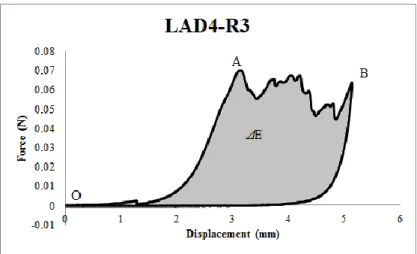
Figure 2.2: First cycles (Load vs Displacement) obtained for one sample (LAD4-R3) ... 33
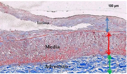
Figure 2.3: Histological picture showing the three layers media, intima and adventitia. . 35
Figure 2.4: Simplified representation of the 2D model used to simulate the dissection through the media ... 36
Figure 2.5: Simulation of the peeling test at 4 different times throughout the test ... 37
Figure 2.6: Traction/separation schematic curve for Bilinear Cohesive Zone models ... 39
Figure 2.7: Cost function values for LAD6 case with respect to the variation of T0 (cohesive) and C10 (elastic) parameters ... 43
Figure 2.8: Experimental versus simulation curves obtained with the minimum cost value, for samples dissected through the intima ... 46
Figure 2.9: Experimental versus simulation curves obtained with the minimum cost value, for samples dissected through the media... 47
Figure 2.10: Characterization of C10 for the three layers of different samples (Histogram format)... 48
Figure 2.11: Average C10 values for the three layers ... 49
Figure 3.1: Schematic of the experimental setup; (a): the Bose machine prescribes a displacement (actuator) and records the resulting force (load cell). The micro-clamps are attached to the actuator and grip the tip of the plaque (b) Schematic of delamination process... 62
Figure 3.2: A representative image of the raw force vs. displacement data. The area under the load-displacement curve represents the energy released during one delamination cycle. The linear region depicted is used to determine the plaque stiffness for each cycle ... 64 Figure 3.3: The estimated ΔA for one cycle, outlined by yellow (top view)... 65 Figure 3.4 : Schematic representation of the plaque model and the underlying aorta. (a): Lm represents the aortic media length, Lp the plaque length, Wm the medial width, Wp the plaque width, Hm the medial height and Hp the maximum plaque height (Lm not shown to scale); (b): 2D representation of the atherosclerotic plaque (green) attached by cohesive elements to the underlying aorta (blue), lying on the gray rigid surface (S). The bottom edge of S, the left & right edges of (A+S), and the top left edge of A were clamped to simulate experimental testing conditions. The reference point represents the master node where displacement boundary conditions were applied. ... 67 Figure 3.5: Simulation of the peeling test at 4 different times throughout the test ... 70 Figure 3.6: Traction/separation curve for Bilinear Cohesive Zone model ... 72 Figure 3.7: Variation of cost function values with respect to C10, with T0=0.05-0.10 MPa
for the sample 173P1 ApoE-/- Col8-/- ... 75 Figure 3.8: Force-displacement curve obtained after simulation for 1 sample. The curve consists of three segments: 1 represents the deformation of the attached peel arm of the plaque, 2 represents the separation phase where the cohesive elements are deleted to simulate the separation, and 3 represents the unloading phase. Segment 2 displays
serrations related to the deletion of cohesive elements ... 77 Figure 3.9: Experimental vs simulated force-displacement curves and strain vs kinetic energy for the first delamination cycles from four ApoE-/- mice ... 79 Figure 3.10: Experimental vs simulated force-displacement curves and strain vs kinetic energy for the first delamination cycles from four ApoE -/- Col8-/- mice ... 80 Figure 3.11: Histograms of average identified values and standard deviations for (a) G, (b) T0, and (c) C10... 82
Figure 3.12: Average and standard deviation of the G values obtained for the 8 months and 6 months ApoE-/- mouse groups ... 85 Figure 4.1: Experiment vs numerical load displacement curves for two successive cycles using same material parameter values obtained for the first cycle ... 93 Figure 5.1: (a) Example of the strain energy and the total energy curves vs crack length, for Gc = 0.0025 N/mm (b) the average ratio of (∆S/∆a) / (∆T/∆a) vs. Gc values ... 112 Figure 5.2: Force vs Displacement curves obtained experimentally for the 5 plaques tested from the ApoE-/- mouse group ... 115
xx
Figure 5.3: Force vs Displacement curves obtained experimentally for 6 plaques tested from the ApoE-/- Col8 -/- mouse group ... 116 Figure 5.4: Force vs Displacement curves obtained experimentally for the remaining 3 plaques tested from the ApoE-/- Col8 -/- mouse group ... 116
CHAPTER 1 INTRODUCTION AND STATE OF ART
Section 1 – Biological introduction
Anatomy of healthy arteries I –
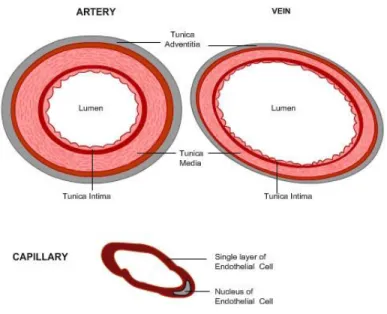
Each individual has his own arterial tree. The shapes, lengths or even the positions of the various arteries and veins are very variable from one person to another. This particularity is due to the growth and history of each person, which leads to important anatomical differences. Nevertheless, the arteries all have a common structure: the arterial walls are composed of three concentric layers6, as represented in Figure 1.1:
- The intima (inner coat) consists of endothelial cells. Endothelial cells are flat cells which interleave into each other forming a smooth surface limiting friction with the blood. They are fixed on a basal lamina, assembled of proteins and extra-cellular glycoproteins, delivering nutrients and removing wastes from the endothelial layer. Endothelial cells themselves are surrounded by connective tissue (cells separated by an extracellular matrix) called the sub-endothelial layer7.
- The media (tunica media) consists of smooth muscle cells embedded in an extracellular matrix composed of collagen and elastin fibers.
2
- The adventitia (tunica adventitia) is mainly composed of collagen, but also elastin, fat cells and blood vessels.
Figure 1.1: A cross section of a normal vessel showing the different layers in human arteries, veins and capillaries (http://www.vascularconcepts.com)
Smooth muscle cells, elastic and collagen fibers are considered the main structural components of the different layers of the artery; each component has its own properties.
Elastic fibers (mostly elastin) have a diameter on the order of microns. They are present in the form of a network8. Elastic fibers can withstand very large deformations (2000%)9.
Collagen fibers provide most of the strength of the artery10.
The morphology and the proportion of each of the three layers can vary depending on the function and location of the artery. Thus there are three different kinds of arteries:
- The elastic arteries, which have the largest diameter and whose media contains a high proportion of elastin. They deform easily under the action of the blood11. This group contains the most well-known arteries such as the aorta, pulmonary artery, or carotid arteries.
- Muscular arteries, which contain more medial smooth muscle cells and less elastin than the elastic arteries12.
Atherosclerotic plaque formation II –
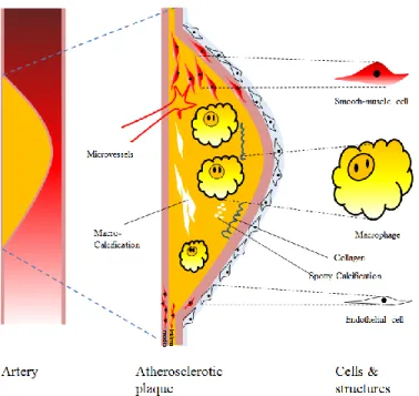
Atherosclerosis is a chronic inflammatory disease of the large elastic arteries characterized by a progressive accumulation of lipids, calcium, and other elements within the intima, leading to the formation of a plaque with complex structure as represented in Figure 1.2. Risk factors such as excessive consumption of tobacco, fatty food causing excessive cholesterol in the blood, stress, genetic predisposition, diabetes, and lack of exercise contribute to its development, eventually leading to symptoms that can have serious consequences13.
4
Figure 1.2: Atherosclerotic plaque composition
Atherosclerosis is a disease mainly affecting the elderly, developing over several decades. Given the aging population and dietary habits in developed countries, several authors have suggested that this disease is the disease of the 21st century14,15,16. This is a complex disease in which the initiation and evolution are still not fully understood 17.
Low density lipoproteins (LDL) are absorbed directly through the endothelial layer of the intima. The intima layer thickens around the lipid core (atheroma) and the fibrous tissue resulting as a consequence of the inflammation. The thickened intima with its lipid core and surrounding fibrous tissue is called an atherosclerotic plaque. Arterial remodeling takes place, and the final result is a compact layer containing primarily collagen and smooth muscle cells, with some contribution of additional matrix proteins. The lipid core does not contain only lipid. It is also a complex tissue containing many
constituents, including lipoproteins, triglycerides, foam cells, leukocytes and macrophages18…
The formation of calcifications may occur during plaque growth. Calcification of plaques can be caused by either genetic factors or by smooth muscle cells and macrophages that have become calcified after undergoing apoptosis while crossing the fibrous cap in their migration into or out of the necrotic lipid core. The calcifications could then be found in both atherosclerotic plaque cap and lipid core19.
Role of collagen in extracellular matrix III –
Collagen is an important component of the extracellular matrix of the arterial wall. Studies have shown that the amount and organization of matrix collagen is related to the mechanical stability of the fibrous cap20. Collagen is the most abundant fibrous protein and satisfies a variety of mechanical functions, particularly in mammals. It is present in skin, cartilage, arteries and in most of the extracellular matrix in general21. There are at least 28 genetically distinct types of collagen22,23. They can be grouped into a number of subfamilies (Table 1.1). From the biomechanical point of view, the fibrillar collagens are of most interest24,25. The fibrillar collagens are defined as a family of structurally related collagens that form the characteristic collagen fibril bundles seen in connective tissue. Fibrillar collagen is a critical component of atherosclerotic lesions. Uncontrolled collagen accumulation leads to arterial stenosis, while excessive collagen
failure combined with inadequate synthesis weakens plaques, making them prone to
6
Table 1.1: Collagens and collagen-like proteins in vertebrates
Human atherosclerotic plaques contain mostly fibrillar collagen types I and III
27
. Type I collagen itself comprises approximately two-thirds of the total collagen28. Type V collagen also increases in advanced atherosclerotic plaques29. Thick type IV collagen depositions are frequently seen in the fibrous cap regions 27,29,30.
Type VIII collagen is considered a short-chain collagen (subgroup of non-fibrillar collagens). It may serve different functions such as stabilization of membranes, and interactions with other extracellular matrix molecules. It is found in basement membranes where it plays a role as a molecular bridge between different types of matrix molecules31, including in ECM of atherosclerotic plaques. Lopes et al. 2013 showed that Type VIII collagen mediates fibrous cap formation in atherosclerosis32.
Conclusion IV –
Studying plaque stability is challenging. Therefore, it is important to understand plaque formation and composition from a biological point of view. But plaque rupture is a mechanical process that needs to be also studied as a mechanical problem. In the next
section, some important mechanical concepts will be presented in order to use them later to have a better understanding of plaque rupture mechanisms.
Section 2 – Mechanical introduction
History and Griffith theory I –
From a mechanical point of view, our medical problem will be solved using fracture mechanics laws. In this part we will introduce as simply as we can fracture mechanics in general.
In 1920, A.A. Griffith started his work on fracture mechanics considering that the theoretical strength of a material was taken to be E/10, where E is the Young's Modulus for the particular material. He was only considering elastic, brittle materials, in which there is no plastic deformation. A lot of experimental tests were done since then to study the critical strength, and it was observed that these critical strength values (strength before failure) were 1000 times less than the predicted values. Griffith wished to investigate this disagreement. He discovered that there were many microscopic cracks in every material and hypothesized that these small cracks actually are responsible for this difference. The presence of these cracks lowered the overall strength of the material because of the increased stress concentration when a load is applied.
Griffith used the energy approach to deduce the energy release rate G, using the first law of thermodynamics. This law implies that during the passage from a non-equilibrium state to an non-equilibrium state, there is a net decrease in energy. Based on this idea, Griffith explained the formation of a crack. A crack can form or extend only if a process does not increase the total energy. Thus the critical conditions for fracture can be
8
defined as the point where crack growth occurs under equilibrium conditions, with no net change in total energy.
The Griffith energy balance for an incremental increase in the crack area under equilibrium conditions can be expressed by: (Eq. 1.1)
𝑑𝐸 𝑑𝐴= 𝑑𝑆𝐸 𝑑𝐴 + 𝑑𝑊𝑠 𝑑𝐴 (1.1) Where: E: total energy.
SE: potential energy supplied by the internal strain energy and external forces.
Ws: work required to create new surfaces.
The energy release rate G is defined as a measure of the energy available for an increment of crack extension (Eq.1.2)
𝐺 = 𝑑𝐸 𝑑𝐴−
𝑑𝑆𝐸 𝑑𝐴
(1.2)
So G measurements can define a fracture parameter, which is the energy release rate during the dissection phase; the challenging part is to measure experimentally the G values.
Cohesive models II –
Delamination is defined as the act of splitting or separating a laminate into layers. Delamination along an interface plays a major role in limiting the toughness and ductility of multi-phase materials. This motivated considerable research on the separation of interfaces using finite element models. Delamination of the interface can be modeled by traditional methods such as nodal release techniques. On the other hand, it is possible to use other techniques that simulate failure by adopting relations between tractions and separations, and introducing a critical fracture energy representing the energy required to separate the interface between surfaces. This technique is called the simulation by cohesive zone model (CZM). The definition of traction-separation laws used depends on the choice of elements and the surrounding material behavior. Generally, the traction-separation law Τ = f(δ), cannot be identified directly. Most of the traction-traction-separation laws used in the literature contain at least two parameters: the cohesive strength T0 and the
critical separation δf 33. It has been shown that the shape of the law has an effect on crack
propagation even if the same T0 and δf are used34. A bilinear traction-separation cohesive
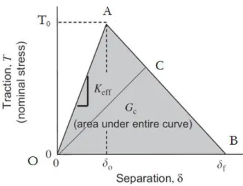
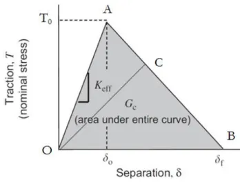
law is considered here. Figure 1.3 depicts this law. It shows linear elastic loading (OA), followed by linear softening (AB). The normal maximum contact traction is reached at point A and denoted as T0. Separation starts at point A and ends at point B when the
normal contact traction reaches zero. The area under the OAB curve is the energy released due to complete separation, which is termed the critical fracture energy per unit area. It is assumed that separation is cumulative and that any unloading/reloading cycle induces a purely elastic response along line OC.
10
Figure 1.3: Traction/separation schematic curve for bilinear cohesive zone models
The parameters of the bilinear traction/separation cohesive law to be characterized are: Keff(MPa/mm), T0(N/mm) and δf (mm).
Mechanical properties of arterial and atherosclerotic plaque components III –
Smooth muscle cells, elastin and collagen fibers are considered as the main structural components of the different layers of the artery.
Elastin fibers have a linear elastic behavior with a Young's modulus on the order of 1 MPa8,9. However, due to the presence of collagen fibers, the arteries have a strongly nonlinear behavior with a rigidity that tends to increase with the applied mechanical load. Three zones are generally considered on the stress-strain curve of an artery (Figure 1.4).
Smooth muscle cells play an important role in the mechanical response of the tissue. The vessel tends to contract from a wall pressure threshold, and to relax from a shear stress threshold applied to the arterial wall35.
The vast majority of studies on the mechanical behavior of arteries use a hyperelastic model and define an elastic strain energy function, logarithmic, polynomial or exponential7,36. Burton37 showed that the intima makes a very small mechanical contribution, which could be expected given the low thickness of this layer. The other two layers are the media and the adventitia. Both provide the majority of resistance and mechanical behavior.
Figure 1.4: Stress Strain arterial response
In 1967, Sacks and Thickner measured different elastic moduli between the radial, circumferential and axial directions on canine femoral arteries 38,12. These studies therefore suggest that the behavior of arteries is anisotropic. A system is called anisotropic when the mechanical properties are dependent on the considered direction. This property was confirmed two years later by Patel et al. who worked on the carotid arteries of dogs and showed that the circumferential direction of the artery was generally stiffer than the axial direction39. The mechanical behavior of arteries could be modeled by
12
three groups of mechanical properties, depending on the axial, radial, and circumferential directions. One of the major characteristics of the vessels is the existence of circumferential residual stresses. This phenomenon can be observed directly by cutting an artery radially: the ring opens naturally as residual stresses are released. In vivo, it seems that the stress level across the arterial wall is offset in large part by blood pressure7,40. It is known that the residual stresses are a result of growth and permanent remodeling of the artery. Saini et al.41 showed that the elastin fibers are the main element responsible for these residual stresses, although it has been proven that collagen fibers also play an important role42.
Many studies have confirmed this observation of the existence of residual stresses in the arterial wall43,44,45,7. Chuong and Fung40 suggested that it was possible to quantify the residual stresses by measuring the opening angle of the artery once cut radially. The problem is more complex in reality as it has been shown that opening angles are different between the media and adventitia layers46,47, and even between the external and internal parts of the media48. Many other authors have proposed computational strategies to predict the stresses in arterial wall49.
Conclusion IV –
To study plaque separation from a mechanical point of view, mechanical laws should be used depending on the mechanical process. In layer separation problems, fracture mechanics is the field of interest. In the case of experimental work, it is important to understand the Griffith theory. And in numerical work, cohesive zone models can be
implemented to model the separation and to understand dissection properties. In the next section, a state of the art literature review is presented to show how these mechanical principles and laws have been applied to biological tissues to study arterial dissection or atherosclerotic plaque rupture.
Section 3 – State of art and literature review
Arterial dissection I –
Arterial dissection may lead to serious complications such as myocardial ischemia, ischemic stroke and other fatal consequences50,51. It begins with an intimal tear that propagates into the vessel wall and leads to the creation of a false lumen51. Separation could occur between the intima and the media, between the media and the adventitia, or within layers (intima and media)52.
Many factors contribute to arterial dissection such as elastin fragmentation, loss of smooth muscle cells, atherosclerosis, and hypertension52,53. 60% of coronary artery dissection cases occur in the left anterior descending coronary, and coronary atherosclerosis is one of the most frequent pathologies leading to coronary artery dissection54.
In order to better understand the mechanical process of dissection, many studies have been realized in which the dissection strength between different interfaces was measured
51,55,56
. Wang et al. 2014, were interested in the LAD (Left Anterior Descending) coronary artery, since no data had previously been reported in the literature3. This study used peeling tests to characterize the adhesion strength for dissection within medial and intimal layers. The peeling test was designed to measure the dissection strength at
14
different interfaces within the arterial wall in terms of local energy release rate, G. This method gave quantitative data that helped to provide a better understanding of arterial dissection mechanisms. Histological studies were performed to complement the mechanical tests by confirming the exact dissection locations and examining the microstructural characteristics at the separated surface. The results showed that there is a statistically significant difference in dissection resistance between tearing events occurring within the intima and within the media 3.
Plaque rupture mechanisms II –
A – Histological features of vulnerable plaques
Several studies have used specimens obtained at autopsy to study the stability of atherosclerotic plaques57,58 These studies aimed to identify the histological features that distinguish stable plaques from unstable (ruptured) ones. Histological features of ruptured plaques include the following
- A thin fibrous cap (on the order of 65 μm thick);
- A large lipid core (>40% of plaque volume);
- Angiogenesis within the plaque;
- Decreased collagen content in the fibrous cap;
- Increased inflammatory cell content;
The thin-cap fibroatheroma (TCFA) is widely considered to be the type of plaque most likely to rupture. It is characterized by a fibrous cap < 65 μm thick, which is heavily infiltrated by macrophages. Typically, a TCFA has a large, lipid-rich necrotic core, which contains numerous cholesterol esters, free cholesterol, phospholipids, triglycerides and apoptotic macrophage foam cells, lying between the thin fibrous cap and the media57,59. Many studies used mouse atherosclerotic plaque models and showed that their plaques are less susceptible to rupture than human plaques60. Despite this, mouse plaque models are widely used. A lot of similarities were noticed in advanced atherosclerotic plaques in mouse models with advanced human plaques60,61even if more recent studies had shown that mouse biomechanical properties of plaques and artery size give less propensity to rupture comparing to humans62.
B – Role of circumferential tensile stress in plaque rupture
While histological features remain qualitative data, measuring fibrous cap tensile strength was the subject of many studies aiming to quantify plaque stability. These studies were interested in calculating tensile stresses using 2D finite element models, in combination with histology to estimate the vulnerable geometry in human atherosclerotic plaques58,63,64. It is also possible to separate individual layers from plaques and to identify the mechanical properties of the layers (intima & fibrous cap)65. The mechanical properties of lipid pools were also estimated based on lipid composition in human plaques66. FE analysis of human atherosclerotic plaques has shown that the areas of greatest circumferential tensile stress are generally located at the plaque shoulder, defined as the boundary between the fibrous cap and the adjacent normal wall. It is important to note that these results are related to lesions which have a large necrotic core and a thin
16
fibrous cap58,63,64. This prediction corresponds to clinical observations concerning the most frequent location of plaque ruptures. More observations suggest that additional factors, both biological and mechanical, must be involved to have a better understanding of plaque rupture. For example, it has been found in some numerical studies calculating the maximum circumferential tensile stresses in human plaques that the values were usually different than the failure strengths measured experimentally. Static 2-D finite element analysis underestimated by at least a factor of two the experimentally measured ultimate tensile stresses of tissue strips, suggesting that stresses experienced in vivo would not reach the levels required for plaque rupture63,65. More recent work by Holzapfel and colleagues has shown that there is significant anisotropy in the mechanical properties of the fibrous cap, with lower ultimate tensile stresses measured in the circumferential direction than in the axial direction67. The measure of the shear strain elasticity (SSE) was also used as an indicator to identify vulnerable plaques68, if the absolute value of the SSE is high, the plaque is more vulnerable. The same group has developed an intravascular ultrasound elasticity reconstruction method to have a predictor of plaque vulnerability69, and designed a technique to get strain fields and modulograms for the recorded intravascular ultrasound sequences, in order to have quantitative data taking into account the motion of the heart and therefore better predictions of plaques vulnerability70.
In conclusion, these observations suggest that additional factors, both biological and mechanical, must be considered in plaque rupture studies.
Many other factors than those listed above could play a major role in plaque stability, such as calcification in the fibrous cap or the lipid core19,71. Using finite element analysis, Weinbaum and colleagues have recently shown that microscopic calcifications in the fibrous cap could lead to local stress concentrations which might exceed the mechanical strength of the material19. Material fatigue may play a significant role in plaque rupture, but this factor has received limited attention71,72. Atherosclerotic plaques are subject to cyclical pressure loading as a function of the normal cardiac cycle in vivo. Plaques in certain locations, such as the coronary arteries, also may experience cyclic tensile loading due to changes in the geometry of the heart as it contracts and relaxes. Clinical observations have shown an increased risk of acute cardiovascular events with increases in pulse pressure, consistent with the idea that material fatigue contributes to plaque instability72.
From a fracture mechanics point of view, few studies have attempted to characterize plaque rupture properties. Holzapfel’s group has measured forces required to delaminate the normal human aortic media51. Recently, Pasta and colleagues56 have also measured fracture properties of human aortic media in order to better understand aneurysm rupture mechanisms. Several studies carried out by the Gasser group used the cohesive elements technique in numerical models to represent the propagation of arterial dissection73. The cohesive zone model (CZM) captures the dissection properties of the individual arterial tissues. Gasser assumed the existence of a cohesive zone in which initialization and coalescence of micro-cracks are lumped into a discrete surface, based on the elasto-plastic fracture theory of metals74,75, and on the quasi-brittle fracture theory of concrete76. In his study of plaque dissection during balloon angioplasty, Gasser defined
18
the dissection as a gradual process in which cohesive traction resists separation between adjoining material surfaces. The presence of collagen in arterial layers motivated the use of this cohesive concept. These studies used a novel cohesive zone model with a defined traction separation law in their finite-element simulation to predict that, in the primary phase of material failure, the plaque breaks at both shoulders of the fibrous cap, with initial crack growth being stopped at the internal elastic lamina. In the secondary phase, local dissections between the intima and the media develop at the fibrous cap location with the smallest thickness77. However, the pressures acting on the fibrous cap are much greater during balloon angioplasty than under normal physiological conditions78. Importantly, plaque failure by delamination has been observed clinically during stenting of atherosclerotic human arteries; although the conditions contributing to delamination during this intervention are also well outside the physiological range.
A survey of the literature on plaque rupture reveals that little attention has been directed toward measuring or modeling plaque attachment to the vessel wall as an adhesive interaction. If successful, our proposed studies will provide evidence for an alternative mechanism of plaque rupture, which does not depend solely on mechanical strength of the fibrous cap. In addition, our computational studies will investigate a range of conditions (material properties, physiological parameters such as blood pressure) that contribute to each mechanism of plaque failure. Understanding the multiple mechanisms of plaque rupture will potentially lead to development of new strategies for clinical intervention to reduce the incidence of this potentially lethal event.
Conclusion III –
Previous biomechanical studies of plaque rupture have focused primarily on the tensile strength of the fibrous cap, rather than on the adhesive strength of the cap/wall interface. We propose in this thesis a novel hypothesis regarding mechanisms of plaque rupture. Specifically, we hypothesize that the adhesive strength of the bond between the plaque and the vascular wall is an important determinant of atherosclerotic plaque stability (resistance to rupture). In the following section, we review the studies which have already been published about adhesive strength evaluation and modelling in biomechanics.
Section 4 – Fracture mechanics in soft tissue biomechanics
Experiments I –
Studies dealing with atherosclerotic plaque delamination as a fracture mechanics problem are rare. The Lessner group at the University of South Carolina used fracture mechanics to study coronary arterial dissection and atherosclerotic plaque rupture3,4. In these studies, a method was developed and applied to characterize the fracture energy per unit area. In other words, the aim was to characterize the dissection strength at different interfaces within the arterial wall in terms of local energy release rate. Taking a different approach to explore dissection properties, Chu et al. 2013 measured the fracture toughness79 which is an inherent property describing the ability of a material to resist crack propagation from an existing flaw80.
Some studies took into account the effects of fatigue on the aortic wall. It is important to include fatigue effects, especially in the study of spontaneous rupture of the aorta (SRA), since the aorta is subjected to cardiac pressure cycles. Chu et al. 2013 79
20
tissue are separately governed by the amount of cumulative damage present internally, in a purely fatigue-driven environment79.
Other studies focused on measurement of the energy required to produce the dissection. Table 1.2 summarizes some of the values of the dissection energy characterized on different samples.
Table 1.2: Dissection energy calculated experimentally for different arterial samples in literature
Reference Samples Dissection Energy (J/m2)
Carson et al. 1990 81 Thoracic aorta 159.0 ± 8.9
Roach & Song 199482 Upper abdominal aorta 18.8 ± 8.9
Roach & Song 199482 Lower abdominal aorta 113.4 ± 4.05
Sommer, et al, 200851 Human abdominal aortic media 76±27 (axial)
51±6 (circumferential)
Tong, et al, 201155 Human carotid artery 60±16~75±24 (within media)
Wang et al. 20143 Human LAD coronary artery 20.71±16.47 (within intima) 13.46±7.19 (intima-media interface)
10.31±4.95 (within media)
In summary, we can see that the dissection energy has been characterized for different samples and under different conditions (pathological and healthy cases, for instance). The dissection energy was the major factor measured, since it can be deduced directly from load displacement curves obtained experimentally.
However, refined analyses of the characterized dissection energy are still missing. For example, the contribution of the strain energy to the total energy was never considered. Numerical simulations would offer an interesting possibility to investigate this contribution and its effects, but this has never been done.
Numerical studies II –
Several studies carried out by the Gasser group used the cohesive elements technique to represent the propagation of arterial dissection73. The cohesive material model aims at capturing the dissection properties of the individual arterial tissue. The presensce of collagen fibers in arterial layers motivated Gasser to use cohesive zone model to study the separation between biological layers73. Thus, damage of fiber bridging was considered to be the cause of a gradual decrease of cohesive force after exceeding the limit load.
Gasser et al. 200673 focused on the dissection of the human aortic media in mode I separation. The human aortic media has a highly organized lamellar structure with repeating structural and functional units of elastin, collagen and smooth muscle cells. Based on this lamellar structure, he postulated a cohesive potential per unit area and derived an appropriate traction separation law using the theory of invariants. This law is shown in Figure 1.5. It is composed of two parts; the linear elastic part has stiffness 𝐶𝑛: (Eq. 1.3) 𝐶𝑛 = 𝑡𝑛 𝛿𝑛 (1.3)
22
And the softening part is defined by the traction separation law (Eq.1.4)
𝑡𝑛 = 𝑡0exp (−𝑎𝛿𝑛𝑏)
(1.4) Where 𝑡𝑛 is the elastic traction limit of the cohesive zone related to 𝛿𝑛. 𝑡0 denotes the cohesive tensile strength and, the non-negative parameters a and b aim to capture the softening response of the tissue according to mode I dissection.
Figure 1.5: Elastic and damage loading stages of the cohesive model: state of damage δn, elastic stiffness cn and elastic traction limit tn at δn defined by Gasser et al. 2006 73
The experimental evidence of crack propagation shows that the cohesive behavior is different for opening mode (I) and sliding modes (II and III), even in isotropic materials83. It is therefore necessary to follow the direction of the crack to distinguish the contribution of the normal and tangential components of the separation (displacement jump). An anisotropic cohesive law, able to distinguish the behavior of the cohesive response along the different directions of the cohesive surface, and an anisotropic fracture criterion were used in this study83. The cohesive law used is shown in the Figure 1.6, defining three critical fracture energy values, one for each direction.
Figure 1.6: Set of cohesive laws considered in the model used in Ferrara et al. 2010 study84 . Both cohesive strengths and critical energy release rates are scaling
proportionally. The maximum opening displacement 𝛿c does not change
In any cohesive law used, characterizing the cohesive parameters is challenging. In Gasser and Holzapfel’s study85
, three parameters had to be determined to characterize the cohesive law : t0, a and b. In order to quantify t0, experiments carried out by the same
group were used51. Tensile tests were carried out on circular-shaped specimens along the radial direction and the force displacement curves were measured. According to these experimental data, tn was found equal to 140.1 kPa. The value of parameter « b » (equation 2) used in Gasser’s simulations was estimated by assuming that the material is « plastic-like » with b=2. This value ensures convergence by avoiding a fast decay of the cohesive traction when reaching the cohesive strength, which is typical for quasi-brittle materials. « a » (equation 2) was deduced using an inverse method. The method consisted of varying « a » until a force vs displacement curve matching the experimental curves was obtained. « a » was found to be equal to 6.5𝑚𝑚−1. Computing the critical fracture energy using these parameters gave a value of 4.9 mJ/𝑐𝑚2. According to the values presented in table 1, the value 49 J/m2 falls within the range of experimentally obtained
24
values. Ferrara et al. 83 used a simpler cohesive law, and the parameter to be determined was only Gc (critical fracture energy, which can be deduced directly from the experiments).
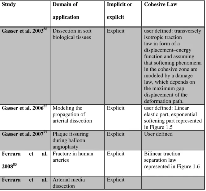
An important point to notice in the listed numerical studies was the integration scheme used for simulations. Table 1.3 shows numerical studies using CZM that deal with medical problems in which separation between layers occurs. For each listed study, an inventory of the resolution scheme and the cohesive law used for the model was cited.
Table 1.3: Numerical studies and the resolution scheme chosen for the models
Study Domain of
application
Implicit or explicit
Cohesive Law
Gasser et al. 200386 Dissection in soft
biological tissues
Explicit user defined: transversely isotropic traction
law in form of a displacement–energy function and assuming that softening phenomena in the cohesive zone are modeled by a damage law, which depends on the maximum gap displacement of the deformation path.
Gasser et al. 200685 Modeling the
propagation of arterial dissection
Explicit user defined: Linear elastic part, exponential softening part represented in Figure 1.5
Gasser et al. 200777 Plaque fissuring
during balloon angioplasty
Explicit User defined
Ferrara et al.
200883
Fracture in human arteries
Explicit Bilinear traction separation law
represented in Figure 1.6
Ferrara et al. Arterial media
dissection
201084 Caballero et al. 201087 Kidney stones fragmentation by direct impact
Explicit bilinear traction separation law
Badel et al. 2014 88 Arterial dissection during balloon angioplasty of atherosclerotic coronary arteries Implicit (Abaqus/stand ard)
Linear elastic part, exponential softening part Untaroiu et al. 201589 Biomechanical and injury response of human liver parenchyma under tensile loading
Explicit Normalized trapezoidal traction-separation relationship
Leng et al. 20155 Atherosclerotic
plaque delamination in ApoE knockout mouse models
Implicit User defined
Most numerical work studying dissection or separation problems in biological tissues used the cohesive element technique as represented in Table 1.3, with differences in the choice of cohesive law and its parameters, and the choice of the integration scheme. A bilinear traction separation law was used and accepted in some of these works, and the explicit scheme seemed to be the most frequent choice in CZM, since there is the presence of large deformations and high non-linearity.
Conclusion III –
The objective of our research is to have a better understanding of two medical problems: arterial dissection and atherosclerotic plaque delamination, using fracture mechanics laws. A review of the literature showed that delamination has always been
26
under-considered by cardiovascular biomechanicists both experimentally and numerically.
In order to address this lack, experimental and computational work has been achieved in this thesis. The aim of the experimental work is to measure the interlaminar tissue adhesion strength first in human coronary artery specimens and then in a mouse model of atherosclerotic plaques. The aim of the computational work is to identify meaningful constitutive parameters from these delamination tests, as adhesive strength is expected to depend on plaque composition and extracellular matrix organization. The choice of integration scheme in simulations was an important factor to ensure convergence and to respond to the high non-linearity related to this problem.
The manuscript is organized as follows: after this introduction, Chapter 2 presents the numerical method used to identify mechanical properties of arterial layers based on the experimental data obtained by Wang et al. 20143. This chapter also presents a novel use of an inverse method to characterize cohesive parameters of the interface between the layers. In Chapter 3, atherosclerotic plaque delamination will be studied. In Chapter 3, the experimental protocol to identify the energy release rate in two mouse genotypes is presented. These two groups of mice are the ApoE -/- vs ApoE -/- Col 8-/- . The aim is to verify whether or not the absence of Col8 in atherosclerotic plaque would be a factor affecting its stability. In chapter 4, based on the numerical method developed in chapter 2, a finite element model of atherosclerotic plaque is presented, to study the delamination using an explicit scheme and the cohesive zone model.
28
CHAPTER 2 ARTERIAL DISSECTION: IDENTIFICATION OF
MECHANICAL AND DISSECTION PROPERTIES IN HUMAN
CORONARY ARTERIES USING AN INVERSE METHOD
Abstract
The cohesive zone model has been widely used in finite element models to study separation between layers for medical problems. In this study, a 2D finite element model was developed using an implicit scheme and a cohesive zone model (CZM) to test an approach that could help identifying material and cohesive parameters using experimental data. The approach consisted of identifying unknown parameters of the model using an inverse method that related the force-displacement curves obtained experimentally. The method was applied to an arterial dissection problem to have a better understanding of the factors playing a crucial role in the dissection mechanisms. Simulation results showed good agreement between experimental and numerical curves when the correct parameters were identified. However there were some limitations due to the use of the implicit scheme, especially for high energy release rate values. No significant differences in identified cohesive parameters were found between dissection through media and dissection through intima cases. Mechanical properties were different between adventitia layers, and intima-media layers which corresponded to reported values
in the literature. Finally, this approach could be used to identify material and cohesive parameters, but the use of an explicit scheme would be more suitable for more complex problems.
Keywords: Cohesive zone model, arterial dissection, mechanical properties,
inverse method, arterial layers
Section 1 – Introduction
Arterial dissection is a rare but potentially fatal condition in which blood passes through the inner lining and between the layers of the arterial wall. It results in separation of the different layers, creating a false lumen in the process. Arterial walls are composed of three layers, called intima, media and adventitia. Separation could occur between the intima and the media, between the media and the adventitia, or within the intima or media. Coronary arteries are among the arteries most prone to atherosclerotic diseases 90, which is one of the most common pathologies associated with coronary artery dissection
54
. The left anterior descending coronary artery accounts for 60% of the cases of coronary artery dissection 90. The different constituents composing arterial layers make the arterial wall a heterogeneous anisotropic tissue. Like most soft tissues, it displays a highly nonlinear behavior, stiffening progressively with increasing applied loads. A study carried out by Eberth et al. 201191 was based on the assumption that the arteries are scalable to different changes (pressure, layer thickness, lumen diameter, length…) and in order to estimate the specific implications of these changes, the study used a 4-fiber family constitutive model to quantify the biaxial passive mechanical behavior of mouse carotid arteries.
30
Gasser and Ogden 2003 92 explained in detail the mechanical behavior of arterial layers and elaborated a constitutive model, denoted Gasser-Holzapfel-Ogden model (GHO model), taking into account the different orientations of fibers constituting the arterial wall layers 93 . Holzapfel et al. explained that biological soft tissues, more precisely the arteries, present preferred directions in their microstructure92. When these materials are subjected to small strains (less than 2-5 %), their mechanical behavior can usually be adequately modeled using conventional laws of linear anisotropic elasticity94. However, under finite deformations, these materials have an anisotropic and nonlinear elastic behavior due to rearrangements in the microstructure, such as reorientation of fibers with the directions of deformation. The simulation of these non-linear effects in finite deformation calls for more advanced constitutive models formulated within the framework of anisotropic hyperelasticity. Hyperelastic materials are described in terms of a strain energy function, which defines the energy stored in an elastic material per unit volume of reference (volume in the initial configuration) in terms of deformation at a given point in the material 92,93,94.
From a biomechanics point of view, the process of dissection can be thought of as a delamination process, and it is defined as separation along the interface. Delamination plays a major role in limiting the toughness and ductility of multi-phase materials, making this particular problem a medical and a mechanical problem that needs to be studied. This has motivated considerable research on the separation of interfaces 94. Several studies performed by Gasser’s group used the cohesive elements technique to represent the propagation of arterial dissection 85. The cohesive material zone model aims at capturing the dissection properties of individual arterial tissues. Gasser assumed the