N° d’ordre : 2811
THÈSE DE DOCTORAT
Présentée par Soukina ETTARFAOUI Discipline : Sciences de l’ingénieurSpécialité : Informatique et Télécommunications
Novel Contribution of Optimization MIMO-OFDM systems
Performances
Soutenue le 04 Décembre 2015 Devant le jury
Président :
M. El-Houssine BOUYAKHF , PES (FS, Rabat, Maroc) Examinateurs :
M. M. Majid HIMMI PES, FSR, Rabat
M. Haitham JABBAR TAHA PES, University of Technology Baghdad, Iraq
M. Rachid EL KOUCH PES, INPT, Rabat
M. Mohammed ELKOUTBI PES, ENSIAS, Rabat
Invité :
M. M.Ahmed FAQIHI PA, ENSIAS, Rabat
Faculté des Sciences, 4 Avenue Ibn Battouta B.P. 1014 RP, Rabat – Maroc Tel +212 (0) 37 77 18 34/35/38, Fax : +212 (0) 37 77 42 61, http://www.fsr.ac.ma
UNIVERSITÉ MOHAMMED
FACULTÉ DES SCIENCES
Soukaina ETTARFAOUI 1 PhD thesis
Acknowledgements
The thesis project presented in this dissertation was performed in the LIMIARF Laboratory (Laboratoire d’Informatique Mathématiques Intelligence Artificielle Reconnaissance des Formes) of the Faculty of Science of Rabat.
First and foremost, I would like to express my sincere gratitude to my advisor Prof. Mohammed Majid HIMMI (Professor at the Faculty of Sciences Rabat) for the continuous support of my PhD study and related research, for his patience, motivation, and immense knowledge. His guidance helped me in all the time of research and writing of this thesis. I could not have imagined having a better advisor and mentor for my PhD study. I would like also to emphasize my wholeheartedly thanks for his second chance he gave me and help me to overcome all the obstacles.
Besides my advisor, I would like to deeply thank my co-supervisor Dr. Haitham JABBAR TAHA, University of Technology of Baghdad-Iraq, for his devotedly help; careful monitoring, worthwhile advices and his endless availability to cooperate dutyfully in spite of the atrocious circumstances in the brother country Iraq.
I am grateful to Prof. El Houssine BOUYAKHF, Professor at the Faculty of Sciences of Rabat and LIMIARF Lab Director, not only for accepting to chair my defense jury, but also for his considerable efforts in order to provide all lab-mates the improved moral and material conditions for better productivity, to boost the scientific research.
My sincere thanks to my reviewer Prof. Rachid EL KOUCH, Professor at the Institut National des Postes et Télécommunications (INPT), for agreeing to report my thesis and the honor for being among the defense jury, and also for his insightful comments and eminent questions which provide a grand vision and help to enhance the quality of this manuscript.
I would like to thank my reviewer Prof. Mohammed ELKOUTBI, Professor at the Ecole Nationale d’Informatique et d’Analyses des Systèmes (ENSIAS), for agreeing to judge my work and fortunately accept to sit among the defense jury.
Soukaina ETTARFAOUI 2 PhD thesis
I am extremely grateful to Prof Moulay Ahmed FAQIHI, Professor at the Ecole Nationale d’Informatique et d’Analyses des Systèmes (ENSIAS), for his great kindness to help and support me, for his congeniality encouragement, he was the first to introduce me to the notion of the Wavelet Transform, and thus, I recognize he shaped the contours of my research axis by raising the problematic while I was in a totally mislead.
I am so grateful to all past and present colleagues at LIMIARF and to all my friends for the joyful and pleasant working environment, and for providing support and friendship that I needed.
Last but not the least, I would like to profoundly thank my family: my parents, Mme Fatima ETTALEB and Dr Mohamed Sidina ETTARFAOUI for their endless love and support throughout my life for the strength to reach the stars and chase my dreams, no word could express how fortunate I am to have such a great wonderful parents! , my lovely husband Dr Zouhir AMEZIANE HASSANI, my little angel Mey, my dearest brothers Khalid ETTARFAOUI and Mahmoud ETTARFAOUI and my sister Dr Mariem ETTARFAOUI, my niece Fatima and nephews Omar and Mohamed Sidina.
Soukaina ETTARFAOUI 3 PhD thesis
Résumé
Mots clés : MIMO, OFDM, IFFT/FFT, WPT, STBC, Alamouti Code, Golden code, BER, SNR,
QAM.
Les travaux menés dans le cadre de la présente étude avaient pour toile de fond la perpétuelle interaction entre les usagers des moyens de communications, de plus en plus exigeants en termes de performance technique et les concepteurs des systèmes de communication, soumis, en ce qui les concerne à une spirale d’accumulation de procédés sans paire.
En guise de contribution à cette problématique, il a été procédé à des travaux sur le système MIMO-OFDM, à l’effet d’optimiser ses aspects les plus significatifs et ce, compte tenu des conditions exigées, de nos jours, par la tendance lourde visant à remplacer la Transformée de Fourier (FFT) par la Transformée en Paquet d’Ondelette (WPT).
A ce titre, l’action menée sur le système MIMO en vue de définir la meilleure valeur de Taux d’Erreur Binaire (BER) a été opérée d’une part, en moyennant deux types d’encodage en block d’espace -temps (STBC) : Alamouti et Golden codes et d’autre part, en augmentant le nombre d’antennes à la réception et le nombre de points de constellation de la modulation QAM.
Au terme de ces essais, un nouveau modèle a été mis au point combinant les systèmes MIMO et OFDM ce qui a permis de procéder d’une part, à une nouvelle appréciation de la performance du BER telle qu’elle est opérée au sein du STBC-MIMO-OFDM et, d’autre part, à une comparaison des performances respectives des deux transformées utilisées FFT et WPT. C’est ainsi qu’il a été révélé que le rendement du système en question avec WPT est plus prononcé et ce compte tenu principalement du fait de l’absence des interférences inter symboles (ISI).
En définitive, il est permis de retenir que l’efficacité des valeurs du BER est établie selon 3 différents points de constellation QAM (16,32,64) ainsi que pour les 3 canaux (AWGN, Flat fading+ AWGN et Frequency Selective fading+ AWGN).
صخلم يف اهزاجنإ مت يتلا لامعلاا سسأتت إ هذه راط ةحورطلاا اوحبصأ نيذلا لصاوتلا لئاسو يلمعتسم نيب مئادلا لعافتلا ةيفلخ ىلع يدعاصت مكارت ةأطو تحت نولغتشي مهرودب اوحبصأ نيذلا لئاسولا هذه يعرتخم نيب و ةيلاع ءادا ةردق اهل نوكت نأب نوطرتشي .لصاوتلا تاودلأريظنلا عطقنم ت ىلع لاغتشلإا مت ،ةيلاكشلاا هذه ةلحلح يف ةمهاسمك و ( ةينق MIMO -OFDM اذخأ كلذ و ةديفم ةقيرطب ءادلآا نيسحت ةيغب ) لادبتسا ىلا يمارلا ماعلا هجوتلا لظ يغ انهار ةبولطملا طورشلا رابتعلإا نيعب FFT ب WPT . ىوتسم ىلع هب مايقلا مت ام نإف ،ددصلا اذه يف وMIMO ل ةميق ىلعا ىلا لصوتلا لجأ نم BER دامتعا ىلا ،ةهج نم فدهي يلآ ةيئانث ىوتسم ىلع ريفشتلا ة ( نامزلا و ناكملا STBC ل طاقنلا ددع و لابقتسلإا دنع تايئاوهلا ددع عفر ىرخأ ةهج نم و ) ريوحتلQAMMDMO OMIM يف نيب عمجي ديدج جذومن دامتعا مت ،براجتلا هذه زاجنإ دعب وWPT و FFT ةنراقم و ىلع ةينبملا ةيلاحلا ةموظنملاب اهيلع لصحملا جئاتنلا WPT تاونقلا نم عاونا ةثلاث ربع كلذ و :AWGN, Flat fading; Frequecy Selective Fading
Soukaina ETTARFAOUI 4 PhD thesis
Résumé et organisation de la thèse
Depuis la fin des années 80 les générations des systèmes de télécommunications n'ont cessé de se développer et de se succéder, tendant, chacun selon son niveau d'élaboration, à assurer à la technologie correspondante, une performance de plus en plus irréprochable.
C'est ainsi que, les procédés de multiplexage utilisant la technique dite "Simple Input Simple Output" (SISO) ont cédé le champ aux procédés dits "Multiple Input Multiple Output" (MIMO) (Entrées multiples, Sorties Multiples).
S'agissant plus particulièrement des procédés MIMO, il importe de spécifier que ceux-ci sont utilisés en matière des réseaux sans fil et des réseaux mobiles et orientés exclusivement afin de transférer les informations sur une longue portée et avec la vitesse et l’assurance requises.
Le présent travail se trouve donc encadré par les termes de cette problématique générale, puisqu'il s'emploie à combiner le MIMO à l’OFDM, qui est une technique de multiplexage moyennant les outils mathématiques qui leur sont associées, afin de tirer profit de leurs avantages mutuels permettant d’obtenir la meilleure efficacité sollicitée.
Et ce, à l’effet d’optimiser le système MIMO-OFDM afin d’assurer le bon acheminement des données de l’émetteur jusqu’au récepteur à travers un canal dans ses différentes étapes et traitera le comportement du système dans plusieurs conditions et son impact sur sa capacité de conserver l’intégrité des données émises (exprimée par un taux faible du BER) avec réduction du bruit (exprimée par la valeur du SNR élevée).
Un des problèmes majeurs en télécommunications est d’adapter l’information à transmettre au canal de propagation, cependant, dans les communications à haut débit, les transmissions sont limitées par des contraintes physiques: le bruit dû aux imperfections des systèmes et la nature physique des composants affectent la transmission du signal émis. La déformation du signal au cours de la propagation est également une autre contrainte physique. Elle impose une bonne séparation temporelle des informations émises afin qu’elles restent bien séparées à la réception. La transmission d'un train de symboles s'accompagne presque inévitablement d'une dispersion des données dans le temps.
Les investigations menées dans le cadre du MIMO, essentiellement orienté vers l’assainissement des systèmes de transmission, appelle néanmoins a être secondé par l’utilisation de modulations multi-porteuses dans laquelle un bloc d’information est modulé par une transformée de Fourier. C’est ainsi que les efforts ont été orientés pour faire contribuer l’OFDM qui, récemment a connu
Soukaina ETTARFAOUI 5 PhD thesis
un vif succès et est normalisée dans différents standards sans fils (IEEE 802.11a, 802.16 (WIMAX), LTE, DVB).
La technique OFDM a le grand mérite de transformer un canal multi-trajet large bande en un ensemble de sous-canaux mono-trajet très simples à égaliser. De plus, l’utilisation ingénieuse de redondance cyclique à l’émission permet de réduire la complexité des terminaux grâce à l’utilisation d’algorithmes à base de FFT rapides. La spécificité de l'OFDM vient du recouvrement mutuel des différentes sous-porteuses, d'une manière orthogonale. Cette orthogonalité permet une utilisation optimale des ressources spectrales et facilite l'implantation numérique.
Il n’en demeure pas moins que la performance maximale du système, telle qu’elle a été envisagéepar Gregory Raleigh, passe par la combinaison des MIMO-OFDM. Le recours à ces deux techniques trouve son fondement dans le besoin de tirer profit des avantages de l’une et de l’autre. En effet, cela constitue une base appropriée pour supporter les applications sollicitant un très haut débit, et garantir une meilleure efficacité spectrale tout en améliorant la diversité spatiale.
Toutefois, il a été établi que la combinaison MIMO-OFDM présente des limites et saurait atteindre sa performance que dans le cas où le MIMO est rassemblé avec une variante spécifique à savoir l’OFDM basée sur la Transformée en Paquet d’Ondelettes WPT (Wavelet Packet Transform WPT). Etant entendu que la variante OFDM basée sur FFT a dû faire appel à des corrections.
Ce travail a contribué à introduire la WPT dans le système MIMO-OFDM. Ce faisant, ce système une fois, analysé et simulé et comparé au système à base d’FFT sous Matlab dans les mêmes conditions, a fait preuve de plus de performance en termes d’intégrité des données (BER) et réduction du bruit (SNR).
Ce mémoire de thèse se décline en 4 chapitres.
Introduction: Le premier chapitre présente l’introduction de la thèse, qui contient une
introduction générale, les objectifs, les contributions et un aperçu de la littérature sur les technologies MIMO, OFDM et leur combinaison MIMO-OFDM.
Chapitre 1 : Ce chapitre est dédié à l’état de l’art de ces technologies, passant d’abord par les
définitions des caractéristiques de propagation des canaux de réseaux sans fil, ensuite l’estimation de canal (Block Type Pilot et Comb Type Pilot Estimation). Une étude exhaustive couvrant tous les aspects du MIMO-OFDM, les deux variantes de l’OFDM à savoir FFT-MIMO-OFDM et
Soukaina ETTARFAOUI 6 PhD thesis
WPT-MIMO-OFDM. C’est ainsi que pour chaque variante, une liste des avantages/inconvénients a été relevée.
Chapitre 2: Ce chapitre couvre essentiellement la contribution intitulé “Effect of QAM
modulation of Diversity Coding for MIMO communication system”, le système MIMO a été modélisé selon 2 types de codes STBC (Alamouti and Golden code) et soumis à différentes conditions y compris le nombre d’antennes et/ou le nombre de points de constellation QAM; Les résultats obtenus représentent les valeurs du BER vs SNR.
Chapitre 3 : Ce chapitre fait l’objet de la contribution intitulée : « Performance Comparison of
Golden and Silver code for STBC MIMO system », constitue une suite du chapitre précedent dont lequel nous avons traité un troisième type de code espace temps à savoir : le Silver code, l’étude introduit également un deuxième type de décodage à part celui utilisé en chapitre 3 le ML Decoder, il s’agit du Sphere Decoder, les simulations ont été faites pour 4-QAM et pour un système de 2Rx 2Tx.
Chapitre 4: Ce chapitre représente la contribution principale de ces travaux, faisant l’objet d’une
nouvelle approche visant à combiner le MIMO à WPT-OFDM, une alternative à FFT-OFDM qui, pour sa particularité de donner une meilleure représentation spatio-temporelle du signal intacte contrairement à la FFT, les 2 modèles de système sont 2*2 (2Tx 2Rx) Alamouti STBC ont été mis en place dans le dessein de calculer le BER vs SNR, et ceci, pour différents canaux (AWGN, Flat Fading and Selective Fading) et pour ces 3 points de constellation QAM (16-32-64) modulation dans une Fréquence Doppler de 500 Hz ,cependant, en terme de complexité, ces travaux ont démontrés que le système OFDM à base de transformée WPT détient une complexité élevée par rapport à celui basée sur la FFT.
Conclusion : Ce chapitre constitue la conclusion générale de la thèse, dans laquelle nous avons
résumé toutes les contributions qui ont apporté à ce travail sa valeur ajoutée, il comprend également les perspectives sur nos projets à venir.
Soukaina ETTARFAOUI 7 PhD thesis
Table of Content
Acknowledgements ... 0
Résumé et organisation de la thèse ... 4
INTRODUCTION ... 12
General introduction ... 13
I. Objectives ... 14
II. Contributions ... 15
III. Literature survey ... 15
IV. Thesis outline ... 22
CHAPTER 1 ... 24
MIMO-OFDM AND WAVELET PACKET... 24
1.1. Introduction ... 25
1.2. Wireless communications channels ... 25
1.3. FFT based MIMO-OFDM ... 36
1.4. WPT based MIMO-OFDM ... 44
1.5. Conclusion ... 49
CHAPTER 2 ... 50
EFFECT OF QAM MODULATION OF DIVERSITY CODING FOR MIMO COMMUNICATIONS SYSTEM ... 50
2.1. Introduction ... 51
2.2. MIMO system ... 52
2.3. Space time block codes ... 53
2.4. Simulation results ... 58
2.5. Conclusion ... 60
CHAPTER 3 ... 62
PERFORMANCE COMPARISON OF GOLDEN AND SILVER CODE FOR STBC MIMO-OFDM SYSTEMS ... 62 3.1. Introduction ... 63 3.2. STBC-MIMO ... 63 3.2.1. Silver code ... 63 3.2.2. Golden code ... 65 3.3. Simulation environment ... 67 3.4. Simulation results ... 70 3.5. Conclusion ... 73 CHAPTER 4 ... 74
Soukaina ETTARFAOUI 8 PhD thesis PERFORMANCE ANALYSIS COMPARISON OF FFT AND DISCRETE WAVELET PACKET
TRANSFORM (DWPT) BASED MIMO-OFDM SYSTEMS ... 74
4.1. Introduction ... 75
4.2. Orthogonal Frequency Division Multiplexing (OFDM) Technology ... 76
4.4. Space Time Block Coding (STBC)- Alamouti ... 78
4.5. Discrete Wavelet Packet Transform (DWPT) ... 81
4.6. New Model of MIMO-OFDM System ... 83
4.7. Simulation Results ... 85
4.8. Conclusions ... 93
Soukaina ETTARFAOUI 9 PhD thesis
Table of Figures and Tables
Figure (i). Single-carrier baseband communication system model ... 16
Figure (ii) OFDM Block Diagram ... 17
Figure (iii): Principle of simple 2*2 MIMO link ... 19
Figure (4i): MIMO Channel model ... 20
Figure (5i): MIMO OFDM scheme ... 22
Figure (1-1): Different physical phenomena ... 26
Figure (1-2): Classification of Fading channel ... 27
Figure (1-3): Large scale fading Vs Small scale fading ... 27
Figure (1-4): Frequency Selective fading spectral density ... 31
Figure (1-5): Block-type pilot arrangement ... 35
Figure (1-6): Block-type pilot arrangement ... 36
Figure (1-7): FFT based OFDM transmitter and receiver ... 38
Figure (1-8): Block Diagram of Space Time Block Coded FFT MIMO-OFDM System Structure ... 39
Figure (1-9): ISI effect of a multipath channel on the received signal without guard interval ... 41
Figure (1-10): OFDM symbols with CP ... 42
Figure (1-11): ISI effect of a multipath channel for each subcarrier ... 43
Figure (1-12): WPT OFDM Transceiver ... 45
Figure (1-13): A-STBC WPT based MIMO-OFDM ... 47
Figure (1-14): IDWPT MIMO-OFDM Transmitter Block Diagram using A-STBC ... 47
Figure (1-15): IDWPT MIMO-OFDM Receiver Block Diagram using A-STBC ... 48
Figure (2-1): Block Diagram of MIMO system ... 53
Figure (2-2): Alamouti STBC for 2Tx1Rx ... 54
Table (2-1): Encoding and transmission process for the (2Tx-1Rx ) space-time block code ... 55
Figure (2-3): Alamouti STBC for 2Tx2Rx ... 56
Table (2-2): Simulation parameters ... 58
Figure (2-4): BER performance of Alamouti 2TX.1Rx (4-QAM and 16-QAM) ... 58
Soukaina ETTARFAOUI 10 PhD thesis
Figure (2-6): BER performance of Alamouti 2TX.1Rx and 2TX.2Rx (4-QAM and 16-QAM) ... 59
Figure (2-7): BER Performance of Golden 2TX.1Rx and 2Tx.2Rx (4-QAM) ... 60
Table (3-1): Simulation parameters ... 70
Figure (4-1): Block diagram of FFT-OFDM System [22] ... 77
Figure (4-2): Block diagram of MIMO System. ... 78
Figure (4-3): FFT based MIMO System ... 79
Figure (4-4): Conceptual block diagram of Alamouti space-time block coding scheme ... 80
Figure (4-5): The system equation ... 80
Figure (4-6): Wavelet Packet Construction tree ... 82
Figure (4-7) Block Diagram for a New Model of MIMO-OFDM System ... 83
Figure (4-8): Block Diagram of FFT-OFDM Modulator and Demodulator... 84
Figure (4-9): Two Transmit and Two Receive (2×2) MIMO channel ... 84
Figure (4-10): Block Diagram of DWPT-OFDM Modulator and Demodulator ... 85
Figure (4-11): BER performance of FFT based MIMO-OFDM system with STBC Alamouti (AWGN channel) ... 87
Figure (4-12): BER performance of FFT based MIMO-OFDM system (STBC Alamouti) at the Flat Fading Channel (500 Hz) and (16,32,64 QAM) ... 88
Figure (4-13): BER Performance of FFT based MIMO-OFDM system at the Selective Fading Channel (500 Hz) and (16,32 and 64 QAM). ... 89
Figure (4-14): BER performance of DWPT based MIMO-OFDM system with STBC Alamouti (AWGN channel) ... 90
Figure (4-15): BER performance of DWPT based MIMO-OFDM system with STBC Alamouti (Flat Fading channel) at 500 Hz and (16,32 and 64 QAM) ... 91
Figure (4-16): BER performance of DWPT based MIMO-OFDM system with STBC Alamouti (Selective Fading channel) at 500 Hz and (16, 32 and 64 QAM) ... 92
Figure (4-17): BER performance of DWPT and FFT based MIMO-OFDM system with STBC for AWGN at (16, 32 and 64 QAM)... 92
Figure (4-18): BER performance of DWPT and FFT based MIMO-OFDM system with STBC for Flat fadinfg channel at (16, 32 and 64 QAM) ... 93
Figure (4-19): BER performance of DWPT and FFT based MIMO-OFDM system with STBC for Selective Freqency channel at (16, 32 and 64 QAM) ... 93
Soukaina ETTARFAOUI 11 PhD thesis
List of Abbreviations
4G 4th Generation
ADSL Asynchronous Digital Subscriber Line
AWGN Additive White Gaussian Noise
BER Bit Error Rate
CP Cyclic prefix
CSI Channel State Information
DAB Digital Audio Broadcasting
DMB Digital Multimedia Broadcasting
DVB Digital Video Broadcasting
FFT Fast Fourrier Transform
ISI Interference Inter Symbol
ICI Inter Carrier Interference
LMMSE Linear Minimum Mean Square Error
LS Least Square
ML Maximum Likelihood
MIMO Multiple Input Multiple Output
MRE Maximum Ratio Combiner
OFDM Orthogonal Frequency Division Multiplexing
PAPR Peak to Average Power Ratio
PC Pilot Carrier
QAM Quadrature Amplitude Modulation
RMS Root Mean Square
SNR Signal to Noise Ratio
STBC Space Time Block Coding
Soukaina ETTARFAOUI 12 PhD thesis
Soukaina ETTARFAOUI 13 PhD thesis
General introduction
Consumer’s demand of an efficient wireless platform never ceases to grow with the large use of smartphones which requires higher data rate, with a wide range of services such as internet browsing, streaming video, and high quality voice/data and so on.
Unlike the typically static and predictable characteristics of a wired channel, wireless channel with its dynamical and unpredictable facet, remains intricate to instantaneously analyze. Thus, the study and optimization of wireless communication channel becomes a common concern for researches in the field in order to meet consumer’s expectations.
MIMO stands for Multiple In Multiple Out, emerged in the mid-1990s from work by engineers at Bell Labs as a natural evolution of long existing beamforming and diversity techniques that use multiple antennas to improve the communication link. MIMO is able to ascertain different paths over the air interface by using multiple antennas at both ends, thus creating sub-channels within one radio channel and increasing the data transmission (or capacity) of a radio link [1]. Considered as a powerful technology using multiple antennas at both the transmitter and the receiver, MIMO is a natural extension of developments in antenna array communication that handles many advantages and bring novelties to the wireless communication channel.
MIMO systems provide a number of advantages over single-antenna-to-single-antenna communication. Sensitivity to fading is reduced by the spatial diversity provided by multiple spatial paths. Under certain environmental conditions, the power requirements associated with high spectral-efficiency communication can be significantly reduced by avoiding the compressive region of the information-theoretic capacity bound [2]. MIMO is present in current and emerging standards, latest wireless routers to enhance the capacity of the wireless local area network (WLAN) and especially in the fourth generation of wireless communications, or 4G. The accepted definition of 4G is that given by the International Telecommunications Union – Radio (IMT-R) under the name International Mobile Telecommunications (IMT) Advanced [ITU-R08]. The leading standards that are now accepted within this definition are WiMAX (defined as IEEE 802.16 [IEE09a]) and 3GPP LTE-Advanced [MB09]. [3]
Another technique of multicarrier modulation became a must in the progression of the wireless digital communication is OFDM which stands for Orthogonal Frequency Division Multiplexing, steady and operational that is the basis of 4G and future 5G.
OFDM has various properties that make it desirable over existing single carrier systems; the main advantage is OFDM’s immunity to frequency selective fading. Single carrier systems can increase their data rate by shortening the symbol time, thereby increasing the occupied bandwidth.
Soukaina ETTARFAOUI 14 PhD thesis
Wideband channels are sensitive to frequency selective fading which require complex equalizers in the receiver to recover the original signal. OFDM overcomes this problem by dividing the wideband channel into a series of narrowband channels which each experience flat fading. Therefore only 1 tap equalizers are required in the receiver, reducing complexity greatly [4]. The general idea of the OFDM transmission technique is to split the total available bandwidth B into many narrowband sub-channels at equidistant frequencies. The sub-channel spectra overlap each other but the subcarrier signals are still orthogonal [5].
MIMO-OFDM is a key technology for next-generation cellular communications (3GPP-LTE, Mobile WiMAX) as well as wireless LAN (IEEE 802.11a, IEEE 802.11n), wireless PAN (MB-OFDM), and broadcasting (DAB, DVB, and DMB).
They consist, both together, a dominant air interface for 4G and 5G broadband wireless communications. It combines multiple input, multiple output (MIMO) technology, which multiplies capacity by transmitting different signals over multiple antennas, and Orthogonal Frequency Division Multiplexing (OFDM), which divides a radio channel into a large number of closely spaced sub channels to provide more reliable communications at high speeds.
Traditional MIMO-OFDM is based on the IFFT/FFT; OFDM divides a wideband spectrum into narrow bands of number equal to the FFT points used.
Many researches have come with the idea to work in Wavelet Transform and make it as an alternative to FFT promising and proving more advantages, the architecture is then based on Wavelet Packet Transform instead of FFT, thus, there is no need to use the cyclic prefix to mitigate the inter symbol interference know as a major drawback in the traditional OFDM.
I. Objectives
This thesis manuscript aims to present the benefit of my doctoral research focusing on the MIMO-OFDM system, the principle purpose is the optimization of the channel communication and the increase of the system’s performance.
The main objectives of the research doctoral thesis are:
1. To present a deep survey and analysis of the state of the art and then draw the relevant defects of MIMO-OFDM;
Soukaina ETTARFAOUI 15 PhD thesis
3. To simulate STBC-MIMO for 2 types namely: Alamouti and Golden codes, under Rayleigh fading channel, for different number of antennas and QAM constellation points thus to improve the data rate;
4. To design a new model of MIMO-OFDM with the approach of the transform wavelet using simulation;
5. To apply this model under 3 channels namely: AWGN, Flat fading + AWGN and Frequency selective fading. For 3 constellation points QAM modulation (16,32;64)
6. To reduce the Bit Error Rate (BER) and multipath effects in the wireless communication system with convincing lower SNR values.
7. To give suggestions ideas for future works.
II. Contributions
The contributions of the present research are as follows:
a. Effect of QAM modulation of diversity coding for MIMO Communications system:
BER Performance of Alamouti 2TX.1Rx (4-QAM and 16-QAM);
BER Performance of Alamouti 2TX.2Rx (4-QAM and 16-QAM);
BER performance of Golden using Brute force ML, 2TX.1Rx and 2TX.2Rx (4-QAM).
b. Performance Analysis Comparison of FFT and Discrete Wavelet Packet Transform (DWPT) Based MIMO-OFDM Systems:
BER Performance in FFT based MIMO-OFDM system with STBC Alamouti for (16,32 and 64) QAM:
BER Performance FFT based MIMO-OFDM system in AWGN channel; BER Performance FFT based MIMO-OFDM system in Flat fading +
AWGN channel;
BER Performance FFT based MIMO-OFDM system in Frequency selective fading +AWGN channel.
BER Performance in DWPT based MIMO-OFDM system with STBC Alamouti for (16,32 and 64) QAM :
BER Performance DWPT based MIMO-OFDM system in AWGN channel; BER Performance DWPT based MIMO-OFDM system in Flat fading +
AWGN channel;
BER Performance DWPT based MIMO-OFDM system in Frequency selective fading +AWGN channel.
III. Literature survey
Soukaina ETTARFAOUI 16 PhD thesis
Future mobile communication systems will in any case require extremely large data rates and therefore large system bandwidth. If conventional single carrier (SC) modulation schemes as shown in Figure (1-1) with the resulting very low symbol durations are applied in this system design, very strong inter-symbol interference (ISI) is caused in wideband applications due to multi-path propagation situations.
Figure (i). Single-carrier baseband communication system model
This means, for high data rate applications, the symbol duration in a classical SC transmission system is extremely small compared to the typical values of maximum multi-path delay in the considered radio channel. In these strong ISI situations, a very powerful equalizer is necessary in each receiver, which needs high computation complexity in a wide-band system. These constraints should be taken into consideration in the system development phase for a new radio transmission scheme. The computational complexity for the necessary equalizer techniques to overcome all these strong ISI in a SC modulation scheme increases quadratic-ally for a given radio channel with increasing system bandwidth and can be extremely large in wide-band applications.
In order to correct this deficit, the notion of multicarrier modulation MCM was set up; in particular Orthogonal Frequency Division Multiplexing (OFDM) has been successfully applied to a wide variety of digital communications applications over the past several years. Although OFDM has been chosen as the physical layer standard for a diversity of important systems, the theory, algorithms, and implementation techniques remain subjects of current interest.
OFDM converts a frequency-selective channel into a parallel collection of frequency flat sub channels. Instead of carrying separate messages, the different frequency carriers can carry different bits of a single higher rate message. The source may be in such a parallel format, or a serial source can be presented to a serial-to parallel converter whose output is fed to the multiple carriers [6].
The subcarriers have the minimum frequency separation required to maintain orthogonality of their corresponding time domain waveforms, yet the signal spectra corresponding to the different subcarriers overlap in frequency. Hence, the available bandwidth is used very efficiently. If
Soukaina ETTARFAOUI 17 PhD thesis
knowledge of the channel is available at the transmitter, then the OFDM transmitter can adapt its signaling strategy to match the channel. Due to the fact that OFDM uses a large collection of narrowly spaced sub-channels, these adaptive strategies can approach the ideal water pouring capacity of a frequency-selective channel [7]. In practice, this is achieved by using adaptive bit loading techniques, where different sized signal constellations are transmitted on the subcarriers; OFDM is a block modulation scheme where a block of information symbols is transmitted in parallel on sub-carriers.
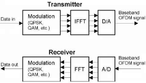
Figure (1-2) bellow shows the general OFDM system structure in a block diagram. The basic principles of the OFDM transmission technique have already been described in several publications.
Figure (ii) OFDM Block Diagram
To sum up, a census of the main advantages of OFDM technology is given bellow:
Makes efficient use of the spectrum by allowing overlap.
By dividing the channel into narrowband flat fading sub-channels, OFDM is more resistant to frequency selective fading than single carrier systems are.
Eliminates ISI and IFI through use of a cyclic prefix.
Using adequate channel coding and interleaving one can recover symbols lost due to the frequency selectivity of the channel.
Channel equalization becomes simpler than by using adaptive equalization techniques with single carrier systems.
Soukaina ETTARFAOUI 18 PhD thesis
OFDM is computationally efficient by using FFT techniques to implement the modulation and de-modulation functions.
Is less sensitive to sample timing offsets than single carrier systems are.
Provides good protection against co-channel interference and impulsive parasitic noise.
ii. MIMO literature survey
Mobile communications have recently increased significantly, besides, the World Wide Web and its applications have spread widely, the possibility to have access to internet, multimedia services and communications wirelessly has accelerated a similar trend: users want to move freely with high quality network coverage during their space displacement.
In addition, it is desirable to avoid having to install the corresponding cables into buildings or houses and to avoid incurring the related costs.
Speech communication for mobile telephones was at the time a tremendous task to achieve wirelessly, and internet and multimedia applications which by nature require higher volume of data to be transmitted both ways through the communication link pose nowadays, a serious challenging problem.
At one time in wireless the term “MIMO” (Multiple Input multiple output) referred to the mainly theoretical use of multiple antennas at both the transmitter and the receiver. In modern usage, “MIMO” specifically refers to a practical technique for sending and receiving more than one data signal on the same radio channel at the same time via multipath propagation.
Used and still requested in many incumbent standards including IEEE 802.11n (Wi-Fi), IEEE 802.11ac (Wi-Fi), HSPA+ (3G), WiMAX (4G), and Long Term Evolution (4G). More recently, it has been applied to power-line communication for 3-wire installations as part of ITU G.hn standard and HomePlug AV2 specification.
MIMO systems have emerged as an enabling technology to achieve the design goals of contemporary communication systems and have given rise to a proliferation of research activity worldwide, as an ultimate successor of SISO (Single Input Single Output), SIMO (Single Input Multiple Output) and MISO (Multiple Input Single Output), MIMO system which employs multiple antennas in the transmitter and/or receiver, the correlation between transmits and receive antenna is an important aspect of its channel.
Soukaina ETTARFAOUI 19 PhD thesis
In the international research arena, there has been research carried out in MIMO and the research topics considered can be classified into the following categories:
Radio – Channel measurements in terms of how the radio signal propagates through the environment. The goal has been to characterize the channel and derive models of its behavior. Another important factor in this regard is the design of the array antennas used in MIMO and the study of how they impact the performance.
Signal processing – The MIMO signals will need to be processed such that they have algorithms to detect the incoming MIMO signals and successfully decode them. A variety of algorithms have been developed to achieve that.
Coding – Techniques such as space–time codes, Blast mechanisms and Eigen tracking aim at achieving a balance between increasing the data rate and introducing redundancy.
Networking – Linking several mobiles and access points using MIMO simultaneously.
Hardware – Building the actual MIMO systems onto demonstrators, radio frequency (RF) chips and digital signal processing (DSP) chips etc.
The figure (1-3) below shows an illustration of the principle for a simple 2*2 MIMO [1], where effectively two paths have been created due to reflections of buildings at two different locations and the beams have been formed to transmit and receive down the two orthogonal paths:
Figure (iii): Principle of simple 2*2 MIMO link
The system includes 2 transmitters and 2 receivers, if we beam form to both transmitters simultaneously, and the two beams are sufficiently separated, it would be possible to obtain the two streams without them interfering with each other. Indeed, for MIMO to work, it has to be possible for the beams formed at both ends to be able to distinguish different angles from which the antenna can transmit or receive.
Soukaina ETTARFAOUI 20 PhD thesis
Figure (1-4) is a the mathematical projection of the reality aspect of the figure (1-3),
Figure (4i): MIMO Channel model
The transmit streams go through a matrix channel which consists of all paths between the transmit antennas at the transmitter and receive antennas at the receiver. Then, the receiver gets the received signal vectors by the multiple receive antennas and decodes the received signal vectors into the original information. A narrow band flat fading MIMO system is modelled as:
(i)
Where x and y are receive and transmit vectors, respectively, and H and n are the channel matrix and the noise vector, respectively.
To conclude this point, MIMO offers potential summarized for:
larger data rate;
larger spectral efficiency;
larger number of users;
improved range/coverage;
better interference suppression;
better quality of service (QoS);
lower bit-error rate (BER);
Lower Tx power.
However, it should be noted that besides advantages mentioned above, there are some disadvantages listed below:
Soukaina ETTARFAOUI 21 PhD thesis
• Each antenna needs a radio-frequency (RF) unit • Powerful digital signal processing (DSP) unit required
Software complexity:
• Most signal processing algorithms are computationally intensive
Power consumption:
• Battery lifetime of mobile devices • Thermal problems
Antennas:
• Antenna spacing (electromagnetic mutual coupling-e.g. mobile handsets) • RF interference and antenna correlation
iii. MIMO-OFDM literature survey
The evolving 4G wireless system demands very high data rate that can only be meet out by some multicarrier systems. OFDM can efficiently handle data within the limited resource of bandwidth and ensure better diversity once combined with MIMO.
Discussion about the use of multiple antennas in both transmitter and receiver with OFDM to increase the capacity and raise data rate was effected in [8] which authors obtained high BER value for BPSK of OFDM, in [9] the author recommended a novel technique for MIMO-OFDM using CDMA inserted SSK which provides efficient selection for transmitting antennas. After studying and analyzing several research, there are two points that should be taken into consideration; high rate STBC systems have attracted great interest since they are required to build high throughput wireless communication systems and larger number of antennas [10] . The wavelet based OFDM or in particular Wavelet packet Transform remains a novel means to replace traditional FFT based OFDM, many research have been interested in this particular scope. Besides saving bandwidth worry, the use of WPT is favored in multicarrier systems design. The figure (1-5) below shows a MIMO-OFDM scheme:
Soukaina ETTARFAOUI 22 PhD thesis
Figure (5i): MIMO OFDM scheme
The data follows the same stages of OFDM transmitter chain in addition to the MIMO Decoder, in the scheme above, many part of it could be modified and tested, mainly, IFFT/FFT replaced with IDWPT/DWPT.
In [11], a scatter plot analysis of DWT-OFDM is presented for different SNRs, and compared with FFT based OFDM; it is found that Haar and Daubechies based orthonormal wavelets are capable of reconstructing the transmitted symbol at the receiver side and effect of noise is reduced.
IV. Thesis outline
This thesis is organized into 5 chapters as follows:
Chapter 1: This chapter deals particularly with the combination of MIMO with OFDM, after a
large survey of all features of MIMO-OFDM including the its principle, the space time block codes, forms of MIMO channel (Multi-antenna and Multi-user types), the detailed technique, guard time insertion and cyclic prefix and a census of most important advantages and disadvantages are presented and exhaustively analysed.This chapter also focuses on the study of MIMO-OFDM with Wavelet Transform; an alternative to traditional FFT based OFDM, here we approach the wavelet transform with all its variants; Discrete Wavelet Transform and Wavelet Packet Transform (WPT). In addition to a deep analysis in order to draw advantages and disadvantages of WPT-MIMO-OFDM. We will also devote a paragraph to detail the propagation mobile radio channel characteristics namely: the attenuation, multipath effects and another paragraph to detail channel estimation for both Block Type Pilot and Comb Type Pilot Estimation.
Soukaina ETTARFAOUI 23 PhD thesis
Chapter 2: This chapter covers the contribution paper in 2014 Second World Conference on
Complex Systems (WCCS), untitled “Effect of QAM modulation of diversity coding for MIMO communication system”, here the system model is made up of 2 kinds of STBC (Alamouti and Golden code) and simulated under different conditions such as number of antennas and/or number of constellation point QAM; Results obtained are SNR versus BER plots.
Chapter 3: This chapter is considered as a succession of the previous one, it covers the
contribution « Performance Comparison of Golden and Silver code for STBC MIMO system », where we have added another space time code namely “Silver code”, we have compared the BER of 2*2 sytem using 4-QAM modulation of Golden code and Silver code, this was done by 2 types of decoding ML decoder and Sphere decoder.
Chapter 4: In this chapter, the main strength contribution paper in WSEAS Transactions on
Communications Journal, 2 models of MIMO-OFDM systems were developed. Model 1 is FFT based MIMO-OFDM system and the second one is DWPT, the BER for 2*2 antennas is calculated under different channel models (AWGN, Flat Fading and Selective Fading), for 16-32-64 QAM modulation in a Doppler Frequency of 500 Hz, then a discussion of the comparison for simulation results between both systems is made.
Conclusion: This chapter concerns the conclusion and presents suggestions and perspective for
Soukaina ETTARFAOUI 24 PhD thesis
CHAPTER 1
MIMO-OFDM AND WAVELET
PACKET
Soukaina ETTARFAOUI 25 PhD thesis
1.1. Introduction
In future wireless communications systems, the necessity to enhance its platform and mainly high speed transmission is the hot topic for researches in the field. However, fading phenomenon caused by destructive addition of multipath components and interference from other users make the overall quality of service decreased and the demand of an improved wireless communications sustainably increased.
Limited spectral resources make it necessary to utilize the available bandwidth to its maximum extent. Information theory answers the fundamental question about the maximum rate that can reliably be transmitted over a wireless channel. This chapter is devoted to an exhaustive explanation of the thesis research axis, at first, to carry out information-theoretic study by detailing some useful features of wireless communications channels mainly propagation and fading and channel estimation, some other points will be discussed and detailed later on the following chapters. We will also detail the principles and techniques of MIMO-OFDM with itemizing advantages and disadvantages for both traditional FFT based MIMO-OFDM and WPT based MIMO-OFDM.
1.2. Wireless communications channels
1.2.1. Propagation characteristics of mobile radio channels
In wireless communication, radio propagation refers to the behavior of radio waves when they are propagated from transmitter to receiver. Radio waves are mainly affected by physical phenomena and also the fading channel notion. In these paragraphs we will discussed both factors.
1.2.1.1. Physical phenomena
Radio waves are mainly affected by three different modes of physical phenomena namely: reflection, diffraction and scattering in figure (1-1) as shown below:
Soukaina ETTARFAOUI 26 PhD thesis
Figure (1-1): Different physical phenomena
a. Reflection: is the physical phenomenon that occurs when a propagating electromagnetic
wave impinges upon an object with very large dimensions compared to the wavelength, for example, surface of the earth and building. It forces the transmit signal power to be reflected back to its origin rather than being passed all the way along the path to the receiver.
b. Diffraction: refers to various phenomena that occur when the radio path between the
transmitter and receiver is obstructed by a surface with sharp irregularities or small openings. It appears as a bending of waves around the small obstacles and spreading out of waves past small openings. The secondary waves generated by diffraction are useful for establishing a path between the transmitter and receiver, even when a line-of-sight path is not present.
c. Scattering: is the physical phenomenon that forces the radiation of an electromagnetic
wave to deviate from a straight path by one or more local obstacles, with small dimensions compared to the wavelength. Those obstacles that induce scattering, such as foliage, street signs, and lamp posts, are referred to as the scatters. In other words, the propagation of a radio wave is a complicated and less predictable process that is governed by reflection, diffraction, and scattering, whose intensity varies with different environments at different instances. [12].
Soukaina ETTARFAOUI 27 PhD thesis
The information rides on electromagnetic waves, with the consequence that the information undergoes attenuation (fading) due to the interaction of the electromagnetic waves with the physical environment. The signal attenuation by wireless propagation may be due to the distance between communicating nodes, referred to as path loss, or due to shadowing from obstacles such as buildings, or due to constructive and destructive interference of multiple reflections of the electromagnetic wave, referred to as multipath propagation.
The structure of different varieties for the fading channel is in figure (1-2) as shown below [12]:
Figure (1-2): Classification of Fading channel
The fading channel phenomenon can be broadly classified into two different types: large-scale fading and small-scale fading which their relationship in figure (1-3) as shown below [12]:
Figure (1-3): Large scale fading Vs Small scale fading
Soukaina ETTARFAOUI 28 PhD thesis
It occurs as the mobile moves through a large distance, for example, a distance of the order of cell size. It is caused by path loss of signal as a function of distance and shadowing by large objects such as buildings, intervening terrains, and vegetation. Shadowing is a slow fading process characterized by variation of median path loss between the transmitter and receiver in fixed locations.
Large-scale fading is characterized by average path loss and shadowing. Path loss
PL (path loss) is the reduction in power density (attenuation) of an electromagnetic wave as it propagates through space. Path loss is a major component in the analysis and design of the link budget of a telecommunication system.
This term is commonly used in wireless communications and signal propagation. Path loss may be due to many effects, such as free-space loss, refraction, diffraction, reflection, aperture-medium coupling loss, and absorption. Path loss is also influenced by terrain contours, environment (urban or rural, vegetation and foliage), propagation medium (dry or moist air), the distance between the transmitter and the receiver, and the height and location of antennas.
Path loss can be represented by the path loss exponent, whose value is normally in the range of 2 to 4 (where 2 is for propagation in free space, 4 is for relatively lossy environments and for the case of full specular reflection from the earth surface—the so-called Flat Earth model).
Path loss is usually expressed in dB. In its simplest form, the path loss can be calculated using the formula:
(1-1) Where:
- is the path loss in decibels; - is the path loss exponent;
- is the distance between the transmitter and the receiver, usually measured in meters; - is a constant which accounts for system losses.
Shadowing
Shadowing is the effect that the received signal power fluctuates due to objects obstructing the propagation path between transmitter and receiver. These fluctuations are experienced on local-mean powers, that is, short-term averages to remove fluctuations due to multipath fading.
For paths longer than a few hundred meters, the received (local-mean) power fluctuates with a 'log-normal' distribution about the area-mean power. By 'log-normal' is meant that the local-mean
Soukaina ETTARFAOUI 29 PhD thesis
power expressed in logarithmic values, such as dB or neper, has a normal (i.e., Gaussian) distribution.
We distinguish between local means average over about 40, to remove multipath fading denoted by a single over line area means average over tens or hundreds of meters, to remove multipath fading and shadowing denoted by a double overbar.
The received power PLog expressed in logarithmic units (Neper), is defined as the natural logarithm of the local-mean power over the area-mean power, thus
It has the normal probability density
Where σ is the 'logarithmic standard deviation' in natural units. The standard deviation in dB is found from s = 4.34σ. For instance s = 6 dB shadowing is equivalent to σ =1.36. If we convert 'nepers' to 'watts', the log-normal distribution of received (local-mean) power is found
.
Here the factor "1/mean power" occurs due to the conversion of the pdf of PLog to local-mean power.
b. Small-scale fading (Multipath fading):
Small-scale fading refers to rapid variation of signal levels due to the constructive and destructive interference of multiple signal paths (multi-paths) when the mobile station moves short distances. Depending on the relative extent of a multipath, frequency selectivity of a channel is characterized (e.g., by frequency-selective or frequency flat) for small-scaling fading. Meanwhile, depending on the time variation in a channel due to mobile speed (characterized by the Doppler spread).
Rayleigh fading
Rayleigh fading is a statisticalmodelfor the effect of a propagation environment on a radiosignal, such as that used by wireless devices.
(1-2)
(1-3)
Soukaina ETTARFAOUI 30 PhD thesis
Rayleigh fading models assume that the magnitude of a signal through a communications channel will vary randomly, or fade, according to a Rayleigh distribution; the radial component of the sum of two uncorrelated Gaussian random variables.
Rayleigh fading is viewed as a reasonable model for tropospheric and ionospheric signal propagation as well as the effect of heavily built-up urban environments on radio signals. Rayleigh fading is most applicable when there is no dominant propagation along a line of sight between the transmitter and receiver. If there is a dominant line of sight, Rician fading may be more applicable.
Rayleigh fading is a reasonable model when there are many objects in the environment that scatter the radio signal before it arrives at the receiver. The central limit theorem holds that, if there is sufficiently much scatter, the channel impulse response will be well-modelled as a Gaussian process irrespective of the distribution of the individual components. If there is no dominant component to the scatter, then such a process will have zero mean and phase evenly distributed between 0 and 2π radians. The envelope of the channel response will therefore be Rayleigh distributed.
Calling this random variable , it will have a probability density function [12]: (1-5) Where (1-6)
Often, the gain and phase elements of a channel's distortion are conveniently represented as a complex number. In this case, Rayleigh fading is exhibited by the assumption that the real and imaginary parts of the response are modelled by independent and identically distributed zero-mean Gaussian processes so that the amplitude of the response is the sum of two such processes.
Frequency Selective Fading
Frequency selective fading is a radio propagation anomaly caused by partial cancellation of a radio signal by itself — the signal arrives at the receiver by two different paths, and at least one of the paths is changing (lengthening or shortening). This typically happens in the early evening or early morning as the various layers in the ionosphere move, separate, and combine. The two paths can both be sky wave or one is groundwave.
Selective fading manifests as a slow, cyclic disturbance; the cancellation effect, or "null", is deepest at one particular frequency, which changes constantly, sweeping through the received audio.
Soukaina ETTARFAOUI 31 PhD thesis
As the carrier frequency of a signal is varied, the magnitude of the change in amplitude will vary. The coherence bandwidth measures the separation in frequency after which two signals will experience uncorrelated fading.
In flat fading, the coherence bandwidth of the channel is larger than the bandwidth of the signal. Therefore, all frequency components of the signal will experience the same magnitude of fading. In frequency-selective fading, the coherence bandwidth of the channel is smaller than the bandwidth of the signal. Different frequency components of the signal therefore experience uncorrelated fading.
Figure (1-4): Frequency Selective fading spectral density
- The bandwidth of the transmitted signal Bs is much greater than the coherence bandwidth of the channel as shown in figure (1-4).
- The symbol period of the transmitted signal is much smaller than the delay spread (see next paragraph).
- Digital symbol intervals, Ts smaller than 5 or 6 times the delay spread, ds give rise to frequency selective fading (Ts <2πds)
- Typical values of delay spread are 0.2µs (rural area), 0.5µs (suburban area), 3-8µs (urban area), <2 µs (urban microcell) and 50-300ns (indoor picocell).
Delay spread
The delay spread is a measure of the multipath richness of a communications channel. In general, it can be interpreted as the difference between the time of arrival of the earliest significant multipath component (typically the line-of-sight component) and the time of arrival of the latest multipath components. The delay spread is mostly used in the characterization of wireless channels, but it also applies to any other multipath channel (e.g. multipath in optical fibers). Delay spread can be quantified through different metrics, although the most common one is the root mean square (RMS) delay spread.
Soukaina ETTARFAOUI 32 PhD thesis
The importance of delay spread is how it affects the Inter Symbol Interference (ISI). If the symbol duration is big enough compared to the delay spread (typically 10 times as big would be good enough), one can expect an equivalent ISI-free channel. The correspondence with the frequency domain is the notion of coherence bandwidth (CB), which is the bandwidth over which the channel can be assumed flat. Coherence bandwidth is related to the inverse of the delay spread. The shorter delay spread is, the larger is the coherence bandwidth.
Doppler Shift
Doppler shift is the change in frequency of a wave (or other periodic event) for an observer moving relative to its source; apparent shifts in frequency of transmitted signal due to motion of transmitter/receiver or both.
Shift depends on the relative velocity of the transmitter and receiver. The coherence time of the channel is related to a quantity known as the Doppler spread of the channel. When a user (or reflectors in its environment) is moving, the user's velocity causes a shift in the frequency of the signal transmitted along each signal path; corresponding to different rates of change in phase. The difference in Doppler shifts between different signal components contributing to a signal fading channel tap is known as the Doppler spread. Channels with a large Doppler spread have signal components that are each changing independently in phase over time. Since fading depends on whether signal components add constructively or destructively, such channels have a very short coherence time.
For a vehicle moving in a straight line at constant velocity v , the Doppler frequency shift, fd is
given by:
fd=
2𝜋
𝜆
∥ 𝜈 ∥ cos(𝜃(𝑡))
(1-7)In general, coherence time is inversely related to Doppler spread, typically expressed as: (1-8)
Soukaina ETTARFAOUI 33 PhD thesis
1.2.2. Channel estimation
The transmitted signals are received from the multipath fading channel. After removing the guard interval, performing DFT and channel estimation, the demodulated signal of the kth subcarrier can be represented as [6]:
Y(k) =
X (k)H(k) +W(k) 0≤k ≤N−1 (1-9)Where N is the number of sub-carriers, H(k) and W(k) represent the frequency transfer function of the channel and additive white Gaussian noise (AWGN) with zero mean and variance of σ2w. Then the binary information data is obtained back in “signal demapper” block in the process chain is given as:
𝑋
𝑒(𝑘) =
𝑌(𝑘)𝐻𝑒(𝑘) k=0,1,…,N-1 (1-10)
The least-square (LS) and minimum-mean-square-error (MMSE) techniques are widely used for channel estimation when training symbols are available [12].
Least Squares (LS) and Minimum Mean Square Error (MMSE)
Since the channel conditions vary, instantaneous channel state information needs to be estimated on a short-term basis. A popular approach is so-called training sequence (or pilot sequence), where a known signal is transmitted and the channel matrix is estimated using the combined knowledge of the transmitted and received signal.
For convenience, equation (2-9) can be written in matrix notation given as: Y = XFh +W (1-11)
Where
X = diag(X0 , X1, …., X N−1) (1-11) i
If the time domain channel vector h is Gaussian and uncorrelated with the channel noise, the frequency domain MMSE for h is given by [13]:
Where,
(1-12)
Soukaina ETTARFAOUI 34 PhD thesis
The term Rhy and Ryy are the cross covariance matrix between h and Y and the auto-covariance matrix of Y respectively. The term σ2
w represents the noise variance. The Least Square (LS) estimator is represented by [13]:
Where,
Then the LS estimator becomes:
Since the radio channel is frequency selective and time varying for wide band mobile communication systems, a dynamic estimation of channel is necessary for OFDM signals [14]. In order to estimate the channel transfer function, the inverse of the channel transfer function is applied to every OFDM frame. This compensates the channel effects very much like equalization technique. There are two types of channel estimations used i.e. block type and comb-type pilot channel estimation techniques.
a. Block –Type Pilot Channel Estimation
A block type of pilot arrangement is depicted in figure (1-5) as show below.
(1-13)
(1-14)
(1-15)
(1-16)
Soukaina ETTARFAOUI 35 PhD thesis
Figure (1-5): Block-type pilot arrangement
In this type, OFDM symbols with pilots at all subcarriers (referred to as pilot symbols herein) are transmitted periodically for channel estimation. Using these pilots, a time-domain interpolation is performed to estimate the channel along the time axis. Let St denote the period of pilot symbols in time. In order to keep track of the time-varying channel characteristics, the pilot symbols must be placed as frequently as the coherence time is. As the coherence time is given in an inverse form of the Doppler frequency fDoppler in the channel, the pilot symbol period must satisfy the following
inequality [12]:
Since pilot tones are inserted into all subcarriers of pilot symbols with a period in time, the block-type pilot arrangement is suitable for frequency-selective channels. For the fast-fading channels, however, it might incur too much overhead to track the channel variation by reducing the pilot symbol period.
b. Comb-Type Pilot Channel Estimation
Comb-type pilot arrangement is depicted in Figure (1-6) as shown below.
Soukaina ETTARFAOUI 36 PhD thesis
Figure (1-6): Block-type pilot arrangement
In this type, every OFDM symbol has pilot tones at the periodically-located subcarriers, which are used for a frequency-domain interpolation to estimate the channel along the frequency axis. Let Sf
be the period of pilot tones in frequency. In order to keep track of the frequency-selective channel characteristics, the pilot symbols must be placed as frequently as coherent bandwidth is. As the coherence bandwidth is determined by an inverse of the maximum delay spread σmax, the pilot symbol period must satisfy the following inequality:
As opposed to the block-type pilot arrangement, the comb-type pilot arrangement is suitable for fast-fading channels, but not for frequency-selective channels.
1.3. FFT based MIMO-OFDM
1.3.1. FFT based MIMO-OFDM Transceiver
MIMO-OFDM is the appropriate compromise to take up the challenge of system with high capacity and reduced multipath fading, Inter Carrier Interference (ICI) and Inter Symbol
Soukaina ETTARFAOUI 37 PhD thesis
Interference (ISI) insuring improved spatial diversity and spectral efficiency. In modern usage, the term “MIMO” indicates more than just the presence of multiple transmit antennas (multiple input) and multiple receive antennas (multiple output). While multiple transmit antennas can be used for beamforming, and multiple receive antennas can be used for diversity, MIMO refers to the simultaneous transmission of multiple signals (spatial multiplexing) to multiply spectral efficiency (capacity).
Traditionally, radio engineers treated natural multipath propagation as an impairment to be mitigated. MIMO is the first radio technology that treats multipath propagation as a phenomenon to be exploited. MIMO multiplies the capacity of a radio link by transmitting multiple signals over multiple, co-located antennas. This is accomplished without the need for additional power or bandwidth. Space-time codes are employed to ensure that the signals transmitted over the different antennas are orthogonal to each other, making it easier for the receiver to distinguish one from another. Even when there is line of sight access between two stations, dual antenna polarization may be used to ensure that there is more than one robust path.
Recently, the use of spatial (or antenna) diversity has been widespread, for the reason that it can be provided without spectral efficiency loss. Receive diversity, that is, the use of multiple antennas on the receive side of a wireless link is thoroughly handled, Diversity is a technique that is mainly employed for receivers to combat fading, hence improving signal detection, and ultimately reducing bit error rates in communications systems. While bettering system performance, the only drawback of diversity is the redundancy of sending replicas of signals or data symbols over time, creating wasted overhead. Because of the randomness of fading transmission channels, diversity has been shown to be an effective technique combating fading. OFDM is a frequency-division multiplexing (FDM) scheme employed as a digital multi-carrier modulation technique, a combination of modulation and multiplexing techniques. OFDM is defined as a multicarrier block transmission system with block of ‘N’ symbols grouped and sent parallel. No interference among the data symbols sent in a block. A high number of closely-spaced orthogonal subcarriers are employed to hold data. The latter is separated into a number of parallel data streams; one per sub-carrier. Every subcarrier is modulated with a traditional modulation scheme at a small symbol rate, preserving the overall data rate similar to traditional single-carrier modulation schemes.
The major contribution to the OFDM complexity problem was the application of the Fast Fourier Transform (FFT) to the modulation and demodulation processes [15]; the technique involved assembling the input information into blocks of N complex numbers, one for each sub-channel.
Soukaina ETTARFAOUI 38 PhD thesis
An inverse FFT is performed on each block, and the resultant transmitted serially. At the receiver, the information is recovered by performing an FFT on the received block of signal samples [6]. The orthogonality allows for efficient modulator and demodulator implementation using the FFT algorithm on the receiver side, and inverse FFT on the sender side. Although the principles and some of the benefits have been known since the 1960s, OFDM is popular for wideband communications today by way of low-cost digital signal processing components that can efficiently calculate the FFT. The time to compute the inverse-FFT or FFT transform has to take less than the time for each symbol.[16] Which for example for DVB-T (FFT 8k) means the computation has to be done in 896 µs or even less.
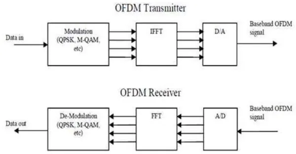
Figure (1-7) below shows a complete block diagram of the typical OFDM transmitter and receiver, including the IFFT and FFT operations:
Figure (1-7): FFT based OFDM transmitter and receiver
Recent researches show that replacing the FFT with wavelet packet could significantly improve the performance of the system; this approach presents a good alternative for not adding a cyclic prefix for the lack of ISI in here, thus, the estimation to obtain higher BER remains very positive, in [17] authors prove that the Wavelet Packet can even offer better PAPR comparing with
traditional FFT based OFDM.
1.3.2. FFT based MIMO-OFDM technique
The multiple orthogonal subcarrier signals, which are overlapped in spectrum, can be produced by generalizing the single-carrier Nyquist criterion into the multi-carrier criterion. In practice,