UNIVERSITÉ DE SHERBROOKE
Faculté de génie
Département de génie mécanique
Analyse et optimisation d'un système de
pompe à chaleur au CO
2
transcritique intégré
avec un éjecteur diphasique
Analysis and optimization of a transcritical
CO
2
heat pump system using a two-phase
ejector
Thèse de doctorat
Spécialité: génie mécanique
Doctoral Thesis Specialty: Mechanical Engineering
Sahar Taslimi Taleghani
Jury:
Mikhail Sorin (supervisor)
Sébastien Poncet (co-supervisor)
Nicolas Galanis (examiner)
Bernard Marcos (examiner)
Armin Hafner (examiner)
Brice Le Lostec (examiner)
To my mother and father, Maryam and Saeed
To my sisters, Sara and Setareh
iii
RÉSUMÉ
L'objectif principal de ce projet de recherche est d'étudier en détail un système de pompe à chaleur transcritique au CO2 utilisant un éjecteur diphasique pour améliorer l'efficacité énergétique et les performances du système.
Un cycle de CO2 transcritique entraîne des pertes importantes lors de la détente (processus isenthalpique) ce qui explique de faibles performances thermodynamiques. Parmi les différents dispositifs de récupération des travaux d’expansion, un éjecteur est proposé pour récupérer une partie des travaux d’expansion dans le processus de régulation et améliorer l’efficacité du cycle. Par conséquent, il est important de comprendre les effets des performances de l'éjecteur ainsi que ses paramètres de fonctionnement pour parvenir à la conception optimale d'un système de réfrigération ou d'une pompe à chaleur.
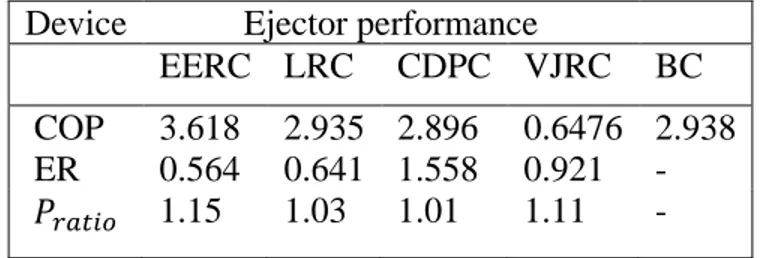
Une étude comparative de différents cycles de réfrigération d’éjecteur au CO2 transcritique a été réalisée et a montré que le cycle de récupération d'expansion de l'éjecteur (EERC) a le plus haut coefficient de performance (COP) et la plus haute efficacité exergétique par rapport aux autres cycles. Le COP et l’efficacité exergétique de l’EERC sont 23.3% supérieurs à ceux du cycle de recirculation de liquides (LRC). Ils sont respectivement 24.9% et 25,5% supérieurs à ceux du cycle de pression de refoulement du compresseur (CDPC) et sont respectivement 5.6 fois et 56.2% supérieurs à ceux et d’un cycle de réfrigération à jet de vapeur (VJRC). Il peut également améliorer le COP et l’efficacité exergétique de 23% et 24%, respectivement, par rapport à un cycle conventionnel.
Étant donné que les éjecteurs peuvent fonctionner dans différentes conditions de fonctionnement autres que le point critique, un modèle numérique détaillé a été développé pour évaluer les performances d'un éjecteur diphasique dans des conditions de simple et double « choking ». Le modèle a été validé avec succès à l’aide des données expérimentales disponibles dans la littérature ainsi que des données fournies par le laboratoire de technologie de l’énergie (LTE) d’Hydro-Québec. Ce modèle permet de prédire les performances de l’éjecteur pour une géométrie fixe (off-design) ainsi que pour des conditions de fonctionnement fixes (on-design).
L'évaluation de l'exergie de l'éjecteur diphasique au CO2 a été réalisée pour les conditions de simple et double "choking" afin d'étudier l'impact de la contre-pression sur les pertes et les rendements exergétiques. Le comportement de trois mesures thermodynamiques, la production d’exergie, la consommation d’énergie et les pertes d’exergie, a été étudié. Les résultats de la comparaison de deux critères de performance exergétique (l’efficacité exergétique transitoire et l’efficacité exergétique de Grassmann) ont montré la présence d’une valeur maximale de l’efficacité exergétique transitoire autour du point critique. Il a également été déterminé que l'efficacité exergétique de Grassmann ne constitue pas un critère approprié pour évaluer les performances d'un éjecteur au CO2 transcritique.
Enfin, un modèle de simulation d'un système de pompe à chaleur au CO2 transcritique avec des échangeurs de chaleur à plaques pour le refroidisseur à gaz et l'évaporateur a été développé et validé expérimentalement. Un modèle de conception d'éjecteur diphasique a été intégré dans le modèle du système de pompe à chaleur pour analyser les différentes performances des systèmes de pompe à chaleur à éjecteur au CO2. Ce modèle est basé sur les surfaces de transfert de chaleur réelles soumises à la contrainte d’une surface totale constante des échangeurs de chaleur. Les
iv
effets des conditions de fonctionnement ainsi que des paramètres de conception de l'éjecteur, tels que le diamètre de la gorge de la buse primaire, le rapport de surface utile, le diamètre de sortie du diffuseur ainsi que le rapport de surface de transfert de chaleur sur les performances du système ont été étudiés. Les conditions optimales d’utilisation et les caractéristiques de l’éjecteur correspondant au COP maximal et à la capacité de chauffage maximale ont été obtenues afin de déterminer la conception optimale d’un cycle au CO2 transcritique. Les rapports de surface de transfert de chaleur ont des effets importants sur le COPh, la capacité de chauffage ainsi que sur la pression optimale du refroidisseur de gaz. Les caractéristiques de l'éjecteur ont des effets importants sur les performances optimales du système. Le diamètre de gorge de la buse primaire et le rapport de surface effective sont deux paramètres importants et peuvent être ajustés pour contrôler les conditions de fonctionnement lors de la conception des cycles à éjecteur. Cependant, le diamètre de sortie du diffuseur n'a pas d'effet significatif sur les performances du système. Le COP et la capacité de chauffage de la pompe à chaleur à éjecteur peuvent augmenter d'environ 17% et 20% respectivement en augmentant le ratio de la surface de transfert de chaleur. Les diamètres de gorge désirés et le rapport de surface efficace de l'éjecteur dans des conditions de fonctionnement données ont été obtenus dans la plage de 1.35 à 1.5 mm et de 7.8 à 8.3 respectivement. Les plages optimales du rapport d'entraînement et du rapport de pression sont également de 0.47 à 0.61 et de 1.16 à 1.35 respectivement.
Mots-clés: cycle de pompe à chaleur, éjecteur diphasique, CO2, modèle thermodynamique, optimisation
v
ABSTRACT
The main objective of this research project is a detailed investigation of a transcritical CO2 heat pump system using a two-phase ejector to improve energy efficiency and system performance. A transcritical CO2 cycle has large expansion losses due to an isenthalpic throttling process which causes the low thermodynamic performance of such systems. Among different expansion work recovery devices, an ejector is proposed to recover part of the expansion work in the throttling process and improve efficiency. Therefore, it is important to understand the effects of ejector performance as well as the operating parameters to reach an optimal design of a refrigeration or heat pump system.
A comparative study of different transcritical CO2 ejector refrigeration cycles was performed under the same cooling capacity and showed that EERC (ejector expansion recovery cycle) has the highest COP and exergy efficiency compared to other cycles. The COP (resp. exergy efficiency) of EERC is approximately 23.3% (resp. 23.3%), 24.9% (resp. 25.5%) and 5.6 times (resp. 56.2%) higher than the corresponding COP and exergy efficiencies of liquid recirculation cycle (LRC), compressor discharge pressure cycle (CDPC) and vapor jet refrigeration cycle (VJRC). The integration of an ejector can also improve the COP and exergy efficiency by up to 23% and 24%, respectively compared to a conventional throttling valve cycle.
Since the ejectors may work at different operating conditions other than the critical point, a detailed numerical model was developed to evaluate the performance of a two-phase ejector under single choking and double choking conditions. The model was successfully validated with the experimental data available in the literature as well as the data provided by Hydro Québec’s energy technologies laboratory (LTE). This model enables to predict the ejector’s performance for a fixed geometry (off-design) as well as for fixed operating conditions (on-design).
The exergy evaluation of the CO2 two-phase ejector was performed for both single and double choking conditions to investigate the impact of the back-pressure on the exergy losses and exergy efficiencies. The behavior of three thermodynamic metrics: exergy produced, exergy consumed and exergy losses was studied. The comparison results of two exergy performance criteria (transiting exergy efficiency and Grassmann exergy efficiency) illustrated the presence of a maximum value of transiting exergy efficiency around the critical point. It was also determined that the Grassmann exergy efficiency is not an appropriate criterion for the evaluation of a transcritical CO2 ejector performance.
Lastly, a simulation model of a transcritical CO2 heat pump system with plate heat exchangers for the gas cooler and the evaporator was developed and experimentally validated. A two-phase ejector design model was integrated into the model of the heat pump system to analyze the different performances of the CO2 ejector heat pump systems. This model was based on the actual heat transfer areas under the constraint of constant total heat exchangers’ area. The effects of the operating conditions as well as ejector design parameters such as primary nozzle throat diameter, effective area ratio, diffuser outlet diameter and also the heat transfer area ratio (the ratio of the gas cooler area to the evaporator area) on system performance were investigated. The optimum operating conditions and ejector characteristics corresponding to maximum COP and heating capacity were obtained in order to determine the optimum design of a transcritical CO2 cycle. The heat transfer area ratios have important effects on COPh, the heating capacity as well as the optimum gas cooler pressure. The ejector characteristics have
vi
significant effects on the optimal performance of the system. The primary nozzle throat diameter and effective area ratio are two important parameters and can be adjusted to control the operating conditions for the design of ejector cycles. However the diffuser outlet diameter has no significant effect on the system performance. COP and heating capacity of the ejector heat pump can increase by approximately 17% and 20% respectively by increasing the heat transfer area ratio from 0.68 (Agc=1.68 m2, Aev=2.46 m2 ) to 4.7 (Agc=3.41 m2, Aev=0.72 m2). The desired throat diameters and effective area ratio of the ejector at given operating conditions were obtained in the range of 1.35-1.5 mm and 7.8-8.3 respectively. The optimal ranges of the entrainment ratio and pressure ratio were also 0.47-0.61 and 1.16-1.35 respectively.
vii
ACKNOWLEDGMENTS
I would like to sincerely thank my supervisor, Prof. Mikhail Sorin for providing me an opportunity to do this project and his expertise, understanding and guidance during my work. I am also grateful to my co-supervisor Prof. Sébastien Poncet for his valuable support, guidance and encouragement. I am extremely thankful to such nice supervision and assistance of you both along the completion of my project.
I would like to express my profound gratitude to members of the jury, for their time to assess my work and their insightful suggestions and comments to improve it.
I would like to acknowledge my industrial partner, Dr. Hakim Nesreddine, at Hydro Québec’s energy technologies laboratory (LTE) for his professional cooperation.
I am grateful to all my friends and colleagues who have supported me along the way and have given me good memories during the last 3 years.
I am profoundly grateful to my parents and my sisters who have provided me through moral encouragement and emotional support, as always for which my expression of thanks does not suffice.
Last, but not least, I owe my deep gratitude to my husband, Payam, for his great patience and personal support at all times.
viii
TABLE OF CONTENTS
TABLE OF CONTENTS ... VIII LIST OF FIGURES ... X LIST OF TABLES ... XIII
... 1
INTRODUCTION ... 1
1.1 Background and motivation ... 1
1.2 Objectives and approach ... 2
1.3 Thesis outline ... 2
... 4
STATE OF THE ART ... 4
2.1 History of CO2... 4
2.2 Transcritical CO2 cycle ... 5
2.3 Principle of an ejector ... 6
2.4 Modeling of a two-phase ejector ... 7
2.5 Mixing theory inside the ejector ... 8
2.6 Ejector component efficiencies ... 9
2.7 Overall ejector efficiency ... 11
2.8 Sound velocity in a two-phase fluid ... 11
2.9 Choking phenomena in the ejector ... 13
2.10Transcritical CO2 ejector expansion work recovery systems ... 14
... 18
ENERGY AND EXERGY EFFICIENCIES OF DIFFERENT CONFIGURATIONS OF THE EJECTOR-BASED CO2 REFRIGERATION SYSTEMS ... 18
3.1 Avant-propos ... 18
3.2 Abstract ... 19
3.3 Introduction ... 19
3.4 Ejector applications for transcritical CO2 cycles ... 20
3.4.1 Vapor jet ejector systems (VJRC, single-phase ejectors) ... 20
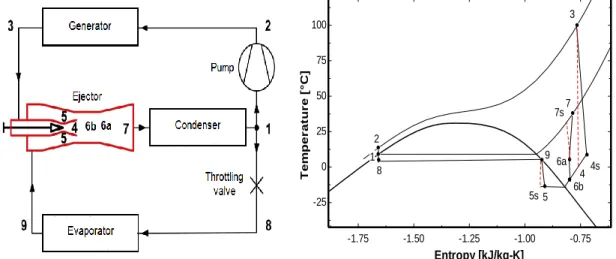
3.4.2 Two-phase ejectors for expansion work recovery (EERC)... 21
3.4.3 Two-phase Ejectors for liquid recirculation (LRC) ... 22
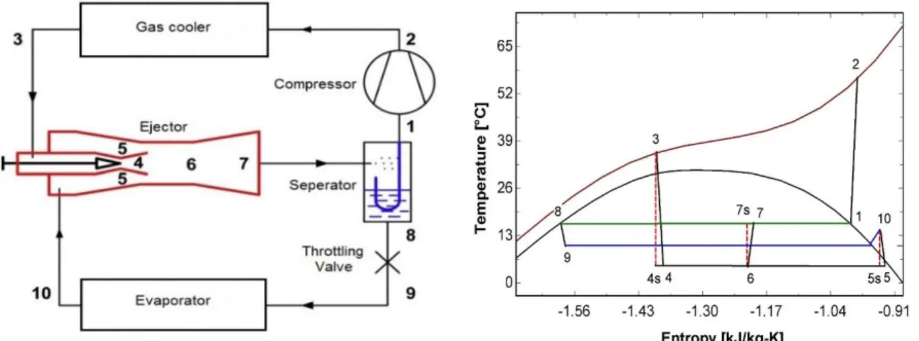
3.4.4 Two-phase ejector for increasing compressor discharge pressure (CDPC) ... 23
3.5 Exergy analysis of different ejector cycles ... 23
3.5.1 Modeling of two-phase flow ejector ... 23
3.5.1.1 Assumptions and calculation procedure ... 24
3.5.1.2 Exergy calculations ... 27 3.6 Results ... 28 3.7 Conclusion ... 29 3.8 Acknowledgments ... 30 3.9 Nomenclature ... 31 ... 32
MODELING OF TWO-PHASE TRANSCRITICAL CO2 EJECTORS FOR ON-DESIGN AND OFF-DESIGN CONDITIONS ... 32 4.1 Avant-propos ... 32 4.2 Abstract ... 33 4.3 Introduction ... 33 4.4 Thermodynamic Modeling ... 37 4.4.1 Assumptions ... 37
4.4.2 Model of a two-phase ejector for fixed geometry (off-design) ... 38
4.4.3 Model of a two-phase ejector for fixed operating conditions (on-design) ... 43
4.5 Results and discussion ... 45
4.5.1 Model validation ... 46
4.5.2 Calculating main dimensions ... 47
4.5.4 Application of the two-phase designed model ... 50
4.5.4.1 Double choking with design inlet conditions and (𝐩𝐝 < 𝐩𝐜𝐫) ... 50
4.5.4.2 Single chocking with design inlet conditions, different ER and 𝐏𝐝 > 𝐏𝐜𝐫 ... 51
4.5.4.3 Double chocking with different primary inlet conditions ... 51
4.6 Conclusion ... 53
4.7 Acknowledgments ... 54
4.8 Nomenclature ... 54
... 55
EXERGY PERFORMANCE OF A TRANSCRITICAL CO2 TWO-PHASE EJECTOR ... 55
5.1 Avant-propos ... 55
5.2 Abstract ... 56
5.3 Introduction ... 56
5.4 Theoretical analysis ... 58
5.4.1 Transiting thermo-mechanical Exergy in a Two-phase ejector ... 59
5.4.2 The Exergy Consumption and Production in a two-phase Ejector ... 59
5.5 Results and discussion ... 61
5.6 Conclusion ... 64
5.7 Acknowledgments ... 65
5.8 Nomenclature ... 65
... 66
PERFORMANCE INVESTIGATION OF A TWO-PHASE TRANSCRITICAL CO2 EJECTOR HEAT PUMP SYSTEM ... 66
6.1 Avant-propos ... 66
6.2 Abstract ... 67
6.3 Introduction ... 67
6.4 Experimental set-up ... 70
6.5 Modeling of the heat pump with plate heat exchangers ... 71
6.6 Ejector integration ... 74
6.7.1 Comparison of basic and ejector cycle ... 79
6.7.2 Performance analysis ... 80
6.7.2.1 Effect of heat transfer area ratio on system performance and the optimal gas cooler pressure ... 80
6.7.2.2 Optimal characteristics of the ejector at different heat transfer area ratios... 82
6.7.2.3 Effect of diffuser outlet area on the system performance ... 84
6.7.2.4 Effect of evaporator pressure on system performance and ejector characteristics ... 85
6.8 Conclusion ... 87 6.9 Acknowledgments ... 88 ... 90 CONCLUSION ... 90 7.1 Conclusion de la thèse ... 90 7.2 Conclusion of thesis ... 92
7.3 Suggested future work ... 94
APPENDIX A ... 96
COMPARISON OF THE EJECTOR MODEL WITH EXPERIMENTAL DATA (LTE) ... 96
x
LIST OF FIGURES
Figure 2.1 Historical cycle of the refrigerants ... 4 Figure 2.2 Phase diagram of CO2 ... 5 Figure 2.3 a) Conventional refrigeration cycle; Pressure-specific enthalpy diagrams: b)
subcritical cycle, c) transcritical cycle ... 6 Figure 2.4 Schematic of an ejector ... 7 Figure 2.5 Schematic of an ejector with (a) constant area mixing, (b) constant pressure mixing ... 9 Figure 2.6 Sound velocity of two-phase CO2 as a function of the void fraction ... 13 Figure 2.7 Structure of the ejector used by Munday and Bagster [23] ... 14 Figure 3.1 Transcritical CO2 vapor jet refrigeration cycle and corresponding Temperature-Specific entropy diagram ... 21 Figure 3.2 Transcritical CO2 ejector expansion recovery cycle and the corresponding
temperature-specific entropy diagram ... 22 Figure 3.3 Transcritical CO2 liquid recirculation cycle and the corresponding temperature-specific entropy diagram ... 22 Figure 3.4 CO2 transcritical ejector cycle to increase the compressor discharge pressure and corresponding temperature - specific entropy diagram ... 23 Figure 4.1 Schematic of an ejector with relevant notations ... 34 Figure 4.2. Transcritical CO2 cycle and corresponding temperature-specific entropy diagram ... 35 Figure 4.3 Critical mode of an ejector ... 37 Figure 4.4 Procedure for CO2 two-phase ejector modeling for a fixed geometry... 39 Figure 4.5 Definition of the polytropic efficiency to evaluate the flow properties; (a) diffuser (b) nozzles ... 40 Figure 4.6. Procedure to evaluate the dimensions of a two-phase ejector ... 44 Figure 4.7 Distributions of axial pressure and mean velocity along the axis of the ejector for double chocking conditions and different back pressures Pd. ... 51 Figure 4.8 Distributions of pressure, velocity and entropy along the axis of the ejector for single choking conditions and different primary flow inlet conditions ... 52 Figure 4.9 Entrainment ratio versus compression ratio for different primary flow pressures . 53 Figure 5.1 Critical mode of an ejector ... 58 Figure 5.2 Schematic of an ejector with relevant notations ... 58 Figure 5.3 Expansion and compression processes on an exergy–enthalpy diagram of a
Figure 5.4 Variations of exergy losses; transiting exergy efficiency and Grassmann exergy efficiency of the ejector with the back pressure ... 64 Figure 5.5 Exergy losses, transiting exergy efficiency, Grassmann exergy efficiency of the ejector for different conditions: (a) single choking; (b) critical point; (c) double choking... 64 Figure 6.1 Schematic of CO2 heat pump set-up ... 70 Figure 6.2 a) Basic transcritical CO2 cycle, b) Transcritical CO2 ejector cycle, c)
Corresponding temperature-specific entropy diagram of the ejector cycle ... 71 Figure 6.3 Comparison between predicted and measured COPh and heating capacity of the transcritical CO2 heat pump ... 74 Figure 6.4 Schematic of an ejector with relevant notations ... 76 Figure 6.5 Calculation flowchart for transcritical CO2 ejector cycle ... 78 Figure 6.6 COPh and heating capacity versus gas cooler pressure for different heat transfer area ratios ... 81 Figure 6.7 Compressor work versus gas cooler pressure for different heat transfer area ratios ... 81 Figure 6.8 Gas cooler outlet temperature versus gas cooler pressure for different heat transfer area ratios ... 82 Figure 6.9 Primary nozzle throat diameter versus gas cooler pressure for different heat
transfer area ratios ... 83 Figure 6.10 Ejector area ratio versus gas cooler pressure for different heat transfer area ratios ... 83 Figure 6.11 Entrainment ratio and pressure ratio versus gas cooler pressure for different heat transfer area ratios ... 83 Figure 6.12 Ejector efficiency versus gas cooler pressure for different heat transfer area ratios ... 84 Figure 6.13 COPh, heating capacity and compressor work; (b) entrainment ratio and pressure ratio versus diffuser outlet diameter, for different heat transfer area ratios ... 85 Figure 6.14 (a) COPh and (b) heating capacity versus evaporator pressure for different heat transfer area ratios ... 85 Figure 6.15 Gas cooler outlet temperature versus evaporator pressure for different heat
transfer area ratios ... 86 Figure 6.16 Compressor work versus evaporator pressure for different heat transfer area ratios ... 86 Figure 6.17 Primary nozzle throat diameter and ejector area ratio versus evaporator pressure for different heat transfer area ratios ... 87 Figure 6.18 Entrainment ratio and pressure ratio versus evaporator pressure for different heat transfer area ratios ... 87
Figure A.1 Installed CO2 ejector test rig at Hydro-Québec ... 96 Figure A.2 Ejector drawing (Obrist Engineering) ... 97
xiii
Table 2.1 Component efficiencies from literature in a CO2 two-phase ejector ... 10
Table 3.1 Constant parameters used in the simulation ... 25
Table 3.2 Comparison of the ejector’s performance of the cycles ... 29
Table 3.3 Exergy destructions and exergy efficiencies of the cycles (Pgc = 88 bar, Tevap = 5˚C, Qevap=72 kW) ... 29
Table 4.1 Comparison of calculated mass flow rates with experimental data for CO2 ... 46
Table 4.2 Validation of the thermodynamic model with experimental data of Smolka et al. [17] 47 Table 4.3 Comparison of calculated pressures at different cross sections of the ejector with experimental data (Banasiak and Hafner [18]) ... 47
Table 4.4 Comparison of calculated dimensions with values from literature ... 48
Table 4.5 Calculated flow properties at different ejector cross sections for CO2 two-phase flow (on-design base case) ... 48
Table 4.6 Effect of polytropic efficiencies on ejector dimensions and efficiencies... 49
Table 5.1 Calculated parameters of a CO2 two-phase ejector for different operating conditions .. 62
Table 5.2 Exergy metrics of a two-phase ejector for double choking conditions and different back pressures Pd (Pd <Pcr) ... 63
Table 5.3 Exergy metrics of a two-phase ejector for single choking conditions and different back pressures Pd (Pd Pcr) and entrainment ratios. ... 63
Table 6.1 Characteristics of the heat exchangers ... 73
Table 6.2 Experimental and simulation operating conditions of the heat pump ... 73
Table 6.3 Heat transfer area ratio of simulated heat exchangers ... 78
Table 6.4 Validation of the simulation model with experimental data of Bilir Sag et al. [78] with the same capacity, operating conditions, and ejector geometry ... 79
Table 6.5 Comparison of energy performance between basic and ejector heat pump cycles ... 79
Table A.1 Pressure indicators and the corresponding cross sections ... 97
Table A.2 Comparison of simulations with experiments –Series 1 (20-03-2018) for Dth=3mm ... 98
1
INTRODUCTION
1.1 Background and motivation
Energy saving and the use of clean energy sources have recently become significant issues. Increasing energy costs, ozone layer depletion and global warming have made an uncertain future for energy and global environment. Therefore the development of new technologies and the use of natural refrigerants with very low GWP coefficient help to find solutions for the future energy needs and reduction of the environmental impact.
All industrial sectors are developing systems to reduce greenhouse gas emissions. Carbon dioxide is an attractive alternative refrigerant in heating and refrigeration systems that has minimum impact on climate change [1]. In addition, it is not toxic, flammable and corrosive so it has no impact on the ozone layer. Using CO2 as a refrigerant in heat pump systems is also competitive with other refrigerants [1]–[3]. It helps to decrease environmental phenomena and to improve energy savings. However, transcritical CO2 compression cycle has a large throttling loss compared to the other refrigerants due to high-pressure change during expansion of a supercritical CO2 to a subcritical state in an isenthalpic throttling process [4].
Ejector is a promising approach to be employed in a transcritical CO2 cycle for expansion [5]. It has simple construction with no moving parts, robust and reliable operation. In an ejector, high-pressure motive (primary) stream expands in the primary nozzle into a low pressure and high velocity. This low pressure entrains a suction (secondary) stream into the mixing section. Inside the mixing section, the two streams exchange momentums and energies and then the uniform mixture compresses to a pressure higher than the inlet pressure of the secondary stream [6].
Since ejector is an important component in ejector refrigeration and heat pump systems, a better understanding of its performance is necessary to realize the potential to improve system efficiency [6]. There are numerous literature reviews which present ejector for CO2 expansion work recovery but most of the existing works are limited to refrigeration cycle and global measurements to investigate overall system performance and energy efficiency improvement [7], [8]. Only a few of them worked on the optimization of a transcritical CO2 ejector cycle considering both operating conditions and geometric parameters of the ejector. Thus because of this limited knowledge about CO2 ejector systems, obtaining an optimum design methodology has received much attention of many researchers. This thesis presents an optimization study and detail investigation of a transcritical CO2 heat pump cycle using an ejector. A two-phase ejector model is developed and incorporated into a heat pump cycle to reveal the effects of various parameters such as operating conditions, ejector geometry and heat transfer areas in a heat pump system. An ejector design model is developed to determine optimum design characteristics. An experimental study is performed to provide a validation of the analytical results of the heat pump and the ejector separately. Furthermore, a parametric study is presented based on the developed model to determine optimal design parameters and their effects on the system performance.
CHAPTER 1 2
1.2 Objectives and approach
The main objective of the project is the analysis and optimization of a transcritical CO2 heat pump system using a two-phase ejector and the detailed investigation of ejector characteristics to propose an efficient design improving the system performance.
This general objective includes the following specific objectives:
Develop a detailed numerical model of a two-phase ejector using CO2 as a refrigerant to predict the performance of an ejector under different operating conditions (single choking, double choking and critical point) and geometric parameters.
Develop a simulation model of a CO2 heat pump using plate heat exchangers.
Perform the experimental analysis of a CO2 heat pump and a two-phase ejector to validate the simulation models of the heat pump cycle as well as the ejector.
Develop a simulation model of an ejector expansion transcritical CO2 cycle to investigate the effects of ejector design parameters as well as operating conditions on the overall system performance.
Perform a parametric study and optimization of a heat pump system with ejector including both operating conditions and ejector characteristics as well as heat exchangers areas. Identify the optimal design values to maximize the COP, heating capacity and ejector
efficiency of a transcritical CO2 ejector heat pump system.
1.3 Thesis outline
Chapter 2 of this thesis presents a review of the transcritical CO2 systems and the principle of the ejector including modeling, governing equations, mixing theory, efficiency, critical mode and sound velocity.
Chapters 3 and 4 present the journal publications that were completed during the doctoral project. Chapter 5 is an article published in a conference proceeding. Chapter 6 is an article submitted for publication. These chapters include a section, “Avant-Propos”, which gives abstract, the status of the articles and their contribution to the thesis in French.
In chapter 3, a comparative study of different configurations of transcritical CO2 ejector cycles is presented to identify the most efficient one. The COP, exergy efficiency and exergy destructions are calculated and compared for the expansion work recovery cycle (EERC), liquid recirculation cycle (LRC), compressor discharge pressure cycle (CDPC) and vapor jet refrigeration cycle (VJRC). Exergy analysis is also performed to determine the amount and locations of irreversibilities within different components of each cycle.
In Chapter 4, a detailed numerical model of a two-phase CO2 ejector is presented to evaluate the ejector performance under different working conditions (single choking, double choking).
First, a new model is developed for a fixed geometry (off-design) which enables to predict the ejector’s performance in both single and double choking conditions. Then, an ejector design model is developed to estimate its dimensions under fixed operating conditions (on-design). The ejector model is then validated using available experimental data in the literature as well as the data provided by Hydro Québec’s energy technologies laboratory (LTE).
Chapter 5 presents an exergy analysis of a transcritical CO2 two-phase ejector for different ejector’s working conditions (single choking, double choking and critical point). The exergy losses and exergy efficiencies are evaluated for different back pressures. Two important metrics, exergy produced and exergy consumed are calculated based on transiting exergy. Grassmann exergy efficiency (ηex,GR) and transiting exergy efficiency (ηex,TR) for three different cases are compared to show the influence of transiting exergy flow inside a two-phase ejector.
In chapter 6, a model of a transcritical CO2 heat pump cycle with plate heat exchangers for gas cooler and evaporator is simulated and experimentally validated. Then the ejector model is integrated within the heat pump system model to evaluate the system performance. Afterward, the parametric analysis is conducted to evaluate the effects of heat transfer areas, ejector characteristics and operating conditions on the COP and heating capacity of a transcritical CO2 ejector heat pump system.
A summary of important conclusions as well as the future work of this study is expressed in chapter 7. Finally, an appendix and the references are given at the end of the thesis.
4
STATE OF THE ART
This chapter presents a general review of a transcritical CO2 cycle, the principle of an ejector and its important characteristics and applications of the ejector in expansion work recovery cycles. First, a transcritical CO2 cycle is introduced and then the ejector performance and some of the important parameters for ejector modeling are described and finally, recent advancements in transcritical CO2 ejector expansion system are presented.
2.1 History of CO
2Carbone dioxide is an old refrigerant which was used in the refrigeration industry more than 100 years ago (1830-1930). However it disappeared after growing need for safety refrigerants and the first generation of synthetic refrigerants (CFCs). Due to chlorine contents in CFCs and their high ozone depletion potential (ODP), HCFCs with much lower ODP replaced CFCs. According to Montreal Protocol CFCs were phased out by January 1996 and HCFCs should be phased out by 2020. After phasing out of CFCs and HCFCs, HFC refrigerants were introduced. They have no ozone depletion potential but high global warming potential (GWP). After 1995 global warming has become an issue. Therefore, using natural refrigerant such as CO2 has become more important. The historical cycle of the refrigerants is shown in Figure 2.1. Nowadays, the divers to use natural refrigerants are as follows:
Kyoto protocol (1997) to reduce the emission of greenhouse gases
EU commission F-Gas regulation to use natural working fluids (NWF) (2014) Montreal Protocol on GWP refrigerates (2016)
Accelerated phasedown of HFCs Ban on HFCs
Governmental restrictions and tax on HFCs
2.2 Transcritical CO
2cycle
Carbone dioxide is a natural refrigerant that is secure, reliable, inexpensive and available. It is not toxic, flammable or corrosive so it has a global warming potential (GWP) of 1 and no impact on the ozone layer. Furthermore, it has a low critical temperature and high working pressure. The critical temperature and pressure are 31.1˚C and 73.7 bars respectively. Figure 2.2 shows the phase diagram of CO2. The vapor pressure of CO2 is much higher and its volumetric refrigeration capacity is 3 to 10 times larger than CFC, HCFC, HFC and HC refrigerants used in the different refrigeration applications. This feature results in a compact size for the compressor and less material consumption for the piping operating with CO2 [1], [2], [9].
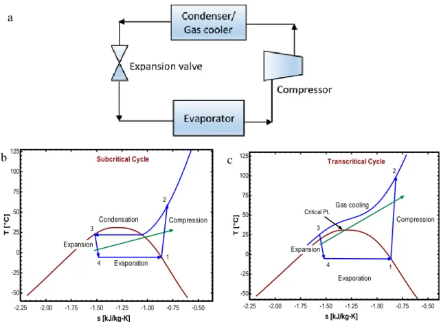
The performance of carbon dioxide is different from other refrigerants used in conventional vapor compression refrigeration and heat pump systems due to its application in transcritical cycles. For a saturating temperature above the critical temperature along with high pressure, the cycle is referred to transcritical [2]. A conventional cycle works under the critical point. Heat absorption occurs in the evaporator at low pressure and heat rejection occurs in the condenser at high pressure but in the transcritical cycle, heat rejection takes place in the gas cooler at a pressure above the critical point. Compared to a subcritical cycle, a CO2 transcritical cycle has larger expansion losses of an isenthalpic throttling process because of the large pressure difference between heat rejection and heat absorption that causes low performance of the cycle [10]. A conventional refrigeration cycle and the corresponding pressure-specific enthalpy diagrams at subcritical and transcritical cycles are shown in Figure 2.3.
In a CO2 transcritical cycle, a high-pressure change occurs when the supercritical CO2 expands to subcritical state yielding a greater throttling loss compared to other refrigerants. Throttling loss can be reduced in different ways. One of the promising ways is to include an ejector. An ejector expansion device can replace the throttling valve to recover the expansion losses and increase the cycle efficiency. It increases the suction pressure of the compressor that results in reducing the compressor work.
2.3. Principle of an ejector 6
Figure 2.3 a) Conventional refrigeration cycle; Pressure-specific enthalpy diagrams: b) subcritical cycle, c) transcritical cycle
2.3 Principle of an ejector
An ejector is a simple and reliable device with no moving part, which can be used in refrigeration and heat pump systems. Using ejector in air conditioning and refrigeration systems based on low-grade energy has been studied since the mid-1950s. Understanding the ejector performance is vital to determine the size, capability, cost and performance of the whole system. It is also important to investigate the ejector characteristics for optimization purpose to obtain appropriate operating conditions and geometrical parameters and improve the system performance. Due to the specific geometry and operating conditions of the ejector, complex flow phenomena may occur including supersonic conditions, shock occurrence, turbulent mixing, two-phase flow (in some cases) and shock-boundary layer interactions. Thus the understanding of the ejector theory is not yet very clear. It requires to use conservation equations of mass, energy and momentum, some gas dynamic equations, state equations, isentropic relations as well as some appropriate assumptions in the description of the flow and mixing within the ejector.
Schematic of an ejector is shown in
Figure 2.4. A typical ejector comprises a primary nozzle, a secondary nozzle, a mixing section and a diffuser. Working process of an ejector can be explained as follows. The primary stream expands through a converging-diverging nozzle from high pressure into a supersonic speed and very low pressure in the mixing section. Its internal energy converts to kinetic energy during acceleration.
-2.25 -2.00 -1.75 -1.50 -1.25 -1.00 -0.75 -0.50 -50 -25 0 25 50 75 100 125 s [kJ/kg-K] T [ ° C] Compression Evaporation Expansion 4 2 3 1 Condensation Subcritical Cycle -2.25 -2.00 -1.75 -1.50 -1.25 -1.00 -0.75 -0.50 -50 -25 0 25 50 75 100 125 s [kJ/kg-K] T [ ° C] Gas cooling Compression Expansion Evaporation 1 2 3 4 Transcritical Cycle Critical Pt. a b c
The low pressure of the primary stream at the nozzle exit plane entrains the secondary stream into the mixing chamber and its velocity increases. Then two streams mix. They exchange momentum, kinetic and internal energies and become a uniform stream. The mixture of the two streams further converts its kinetic energy into internal energy and increases its pressure toward the diffuser exit to a pressure higher than the initial secondary inlet pressure. The ejector performance is defined by two global parameters [11]:
Entrainment ratio, (ER) =mass of secondary flow
mass of primary flow (2.1)
Pressure ratio , (Pratio) = static pressure at diffuser exit
static pressure at secondary inlet (2.2)
Figure 2.4 Schematic of an ejector
2.4 Modeling of a two-phase ejector
Different models of the ejectors exist according to assumptions, governing equations, auxiliary conditions, mixing mechanism and solution methods. Thermodynamic modeling is a simple way to solve the equations in one dimension. It is also easily integrated into a system. Conservation equations of mass, momentum and energy, some gas dynamic equations, state equations, isentropic relations as well as some appropriate assumptions, initial and boundary conditions are used to solve the flow within the ejector. Some assumptions that are usually employed to simplify the problem are as follows: adiabatic walls of the ejector, steady state flow, isentropic or polytropic efficiencies for the nozzles and the diffuser, stagnation points of the streams at inlets and outlet of the ejector, friction losses in the mixing chamber, and dissipation coefficient for mixing losses. Most ejector models presented for CO2 two-phase flows are based on a homogeneous equilibrium model in which both gas and liquid are in thermodynamic and mechanical equilibrium. It means that both phases have the same pressure, temperature, velocity, turbulence kinetic energy and turbulence dissipation [5], [7], [12]–[17]. Although there are some works on the non-homogeneous (heterogeneous) formulation of a CO2 two-phase fluid, flow patterns in CO2 two-phase ejectors
Mixing Section Secondary Nozzle
Primary Nozzle Constant area
duct
Diffuser
Primary Flow
Secondary Flow
2.5. Mixing theory inside the ejector 8 have not been well studied and recorded so far. The design of a two-phase ejector requires advanced knowledge on flow pattern, mass, momentum, energy transfer, shock waves propagation, phase change mechanism and turbulence models. Moreover, each assumption made by the heterogeneous flow model is not completely certain and may be far from real cases. On the other hand, the homogeneous flow model showed it could be a reliable alternative in different situations [18], [19]. Under ideal conditions, the general equations which are used in each section of the ejector are as follows: Conservation of mass ∑𝑖𝑢𝑖𝐴𝑖 = ∑𝑒𝑢𝑒𝐴𝑒 (2.3) Conservation of momentum 𝑃𝑖𝐴𝑖+ ∑ 𝑚̇𝑖𝑢𝑖 = 𝑃𝑒𝐴𝑒+ ∑ 𝑚̇𝑒𝑢𝑒 (2.4) Conservation of energy: ∑ 𝑚̇𝑖(ℎ𝑖 +𝑢𝑖 2 2 ⁄ ) = ∑ 𝑚̇𝑒(ℎ𝑒+𝑢𝑒2 2 ⁄ ) (2.5)
2.5 Mixing theory inside the ejector
The ejector can be defined according to the position of its nozzle exit (NXP). There are two feasible methods, first is the constant area mixing ejector in which the nozzle exit is located within the constant area mixing section. The mixing of the primary and secondary streams occurs inside the constant area section. The second one is the constant pressure mixing where the nozzle exit is located within the converging part of the mixing chamber or suction chamber and the mixing occurs at a constant pressure.
Figure 2.5 shows a constant area and a constant pressure mixing. A normal or oblique shock wave may also occur if there is a supersonic flow mixture inside the constant mixing section that causes a pressure rise and a subsonic flow in the entrance of the diffuser.
The constant pressure and constant area theories have been first developed by Keenan et al. [20]. Their work is based on a one-dimensional (1-D) design of the ejector. For the constant pressure mixing model, they assumed that the primary and secondary flows reach the same pressure at the nozzle exit and then mixing occurs with constant pressure. They also reported that a constant pressure mixing gives better performance of a model than a constant area mixing model and the constant area model provides generally a better agreement with experimental results. However, there are some models in which mixing occurs with both pressure and area changes [21], [22].
Figure 2.5 Schematic of an ejector with (a) constant area mixing, (b) constant pressure mixing
2.6 Ejector component efficiencies
In the thermodynamic model, it needs to implement some coefficients as an approximation to account for the effects of a non-isentropic process, frictional and mixing losses. Isentropic coefficients (𝜂𝑝 ,𝜂𝑠 , 𝜂𝑑) are used to account for non-ideal processes in the nozzles and diffuser. The effects of frictional and mixing losses are also taken into account by using a coefficient (𝜂𝑚𝑖𝑥) in the momentum equation. These parameters are highly dependent on the ejector design and configuration. Therefore it is not possible to extract them easily. They can be determined by CFD and experiments by matching the test and analytical results. Since the ejector model is highly dependent on the efficiency coefficients of the ejector components, it is important to improve the methods for estimating actual ejector coefficients and determine their effects on the ejector geometry. Neither Keenan et al.[20] nor Munday and Bagster [23] have considered irreversibilities due to friction in their works.
Huang et al. [24] conducted experiments using a heat driven system for 11 different ejector specifications using R141b. they determined the ejector component efficiencies by matching experimental data with simulation results of a 1-D ejector model. The constant values for the primary and secondary nozzle efficiencies and an empirical relation for the mixing efficiency were obtained.
CFD modeling was firstly used to determine ejector efficiencies by Varga et. al. [25] for water as a working fluid in air conditioning systems. The simulated enthalpies and isentropic process were
2.6. Ejector component efficiencies 10 compared to determine the primary nozzle, suction nozzle and diffuser efficiencies. They concluded that the primary nozzle efficiency was only dependent on the nozzle throat diameter and it was independent of operating conditions. The suction efficiency was also constant and just reduced when the pressure was above a critical value. The diffuser efficiency depends on the condenser conditions and increases by increasing the back pressure. The mixing efficiency increases with the back pressure until a critical value and then decreases significantly. They also obtained an optimal value of area ratio for ejector performance according to operating conditions. Liu and Groll [26] studied ejector efficiencies based on a model of two-phase flow ejector and measured data. They established empirical relations for the isentropic efficiencies of the primary and secondary nozzles, and the efficiency of the mixing section. Their results showed that ejector component efficiencies highly depend on geometries and operating conditions. The range of 0.5- 0.93 was obtained for the primary nozzle, 0.37-0.9 for the secondary nozzle and 0.5-1 for the mixing section. A transcritical CO2 refrigeration cycle with a controllable ejector at different geometrical and operating conditions was used in their study. The motive nozzle efficiency was dependent on the ejector throat diameter. The suction nozzle efficiency was affected by the motive nozzle throat diameter, primary nozzle exit position, and outdoor air temperature while the mixing efficiency was varied by the primary nozzle exit position and outdoor air temperature.
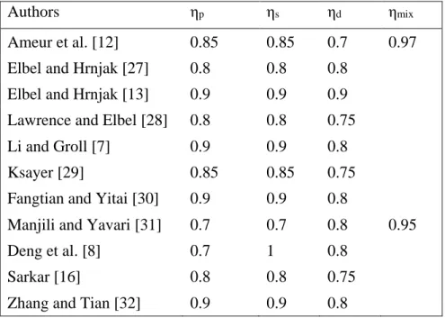
The values of the component efficiencies used in recent works for the modeling of two-phase CO2 ejector are summarized in Table 2.1.
Table 2.1 Component efficiencies from literature in a CO2 two-phase ejector
Authors ηp ηs ηd ηmix
Ameur et al. [12] 0.85 0.85 0.7 0.97
Elbel and Hrnjak [27] 0.8 0.8 0.8 Elbel and Hrnjak [13] 0.9 0.9 0.9 Lawrence and Elbel [28] 0.8 0.8 0.75
Li and Groll [7] 0.9 0.9 0.8
Ksayer [29] 0.85 0.85 0.75
Fangtian and Yitai [30] 0.9 0.9 0.8
Manjili and Yavari [31] 0.7 0.7 0.8 0.95
Deng et al. [8] 0.7 1 0.8
Sarkar [16] 0.8 0.8 0.75
Zhang and Tian [32] 0.9 0.9 0.8
Galanis and Sorin [33] first introduced constant polytropic efficiencies in the ejector (which is used in aerodynamic processes of turbine and compressor) instead of the constant isentropic efficiencies. They used polytropic efficiencies for expansion processes in the nozzles and compression process in the diffuser to consider the effect of the pressure ratio through off-design operation in a 1-D thermodynamic model. It was later used successfully for real gases for single-phase ejectors [21],
[34], [35]. Haghparast et al. [35] also showed that the replacement of isentropic efficiencies by polytropic efficiencies within 1-D ejector models provides more accurate results.
2.7 Overall ejector efficiency
It is difficult to determine the efficiencies of the ejector components from experimental data. For single-phase ejectors, a commonly used efficiency is given by ASHRAE [36]. It is defined as the total enthalpy gained by the primary and secondary streams from the secondary inlet to diffuser outlet divided by the total enthalpy available for recovery from the primary stream inlet to the primary nozzle outlet.
ηejec =ṁp+ ṁs ṁp
hd,out− hs,in
hp,in− hp,out,is (2.6)
Although this efficiency definition works well for single phase ejectors, however, it doesn’t give reasonable efficiency values for two-phase ejectors due to negative and large magnitude enthalpy change between the diffuser outlet and the secondary inlet in the numerator.
A definition of the ejector performance as a function of the entrainment ratio was proposed for two-phase ejectors by Elbel and Hrnjak [27]. An ejector work recovery efficiency is calculated as the amount of expansion work recovery divided by the maximum amount that could be recovered:
ηejec = Wrec
Wrec,max=
ṁs
ṁp
h(Pd,out ,ss,in)−hs,,in
hp,in−h(Pd,out,sp,in) (2.7)
There are other efficiency definitions for two-phase ejector [37]–[39] but all require the knowledge of the mixing section pressure while the efficiency of Elbel and Hrnjak (Eq. 2.7) does not require it. It only depends on the inlet and outlet conditions of the ejector. This efficiency definition has been used by other researchers [40], [41].
2.8 Sound velocity in a two-phase fluid
Calculation of the sound velocity is very important to obtain Mach number (M) under critical flow conditions and analyzing chocking phenomena. In single-phase compressible flows, it can be obtained by:
a2 = (∂P
∂ρ)s (2.8)
M =u
a (2.9)
where 𝑢 is the flow velocity and 𝑎 is the sound velocity. The Mach number is equal to one at the throat of the ejector nozzle in a single-phase reversible flow.
2.8. Sound velocity in a two-phase fluid 12 In a two-phase flow, the speed of sound is not easy to calculate especially near the liquid saturation line where liquid and vapor gradients increase very rapidly at a nonlinear rate. In two-phase flows, pressure and temperature are not independent and the sound velocity depends on the physical properties and interphase area of the fluid.
Wood [42] proposed the following relation for the sound velocity, which was imposed by a homogeneous two-phase model. This model has been used in extensive publications [43]:
𝑎2 = 1 𝜌̅ 1 ( 𝛼𝑣 𝜌𝑣𝑎𝑣2+ 1 − 𝛼𝑣 𝜌𝑙𝑎𝑙2 ) (2.10)
where 𝛼𝑣 is gas volume fraction (void fraction) defined by:
𝛼𝑣 = 𝑉𝑣
𝑉𝑣+ 𝑉𝑙 (2.11)
Yazdani et al. [43] used the relation proposed by Brennen [44] based on the change of volume fraction in thermodynamic relations including homogeneous equilibrium and homogeneous frozen expression: 1 𝜌𝑎2 = 𝛼𝑣 𝑃 [(1 − 𝜖𝑣)𝑣+ 𝜖𝑣𝑔𝑣] + 1 − 𝛼𝑣 𝑃 𝜖𝑙𝑔𝑙 (2.12)
Where 𝜌 is the average density of the two-phase fluid, and g are the thermodynamic properties that can be calculated from local pressure, density and enthalpy of the fluid [44].
In another work, Nakagawa et al. [45] proposed the following relation:
𝑎2 = 𝑃
𝛼𝑣(𝛼𝑣𝜌𝑣+ (1 − 𝛼𝑣)𝜌𝑙) (2.13) Ameur et al. [12] reviewed several relations for the computation of the two-phase velocity and proposed a relation for the sound velocity relied on the homogeneous two-phase model:
𝑎2 = 1 𝜌2[𝑥 1 𝜌𝑣2( 𝜕𝜌𝑣 𝜕𝑃)𝑠+ (1 − 𝑥) 1 𝜌𝑙2( 𝜕𝜌𝑙 𝜕𝑃)𝑠] −1 (2.14) where 𝜌 =1 𝑣̅= 𝛼𝑣𝑣+ (1 − 𝛼𝑣)𝑙 (2.15) 𝑣̅ = 𝑥𝑣𝑣+ (1 − 𝑥)𝑣𝑙 (2.16)
Lund and Flatten [46] established a hierarchy of relaxation models to calculate sound velocities in two-phase flows. They studied the influence of equilibrium assumptions on the propagation of
pressure waves. They imposed three sound velocities: a pressure equilibrium (p equilibrium), a temperature equilibrium (P, T equilibrium) and a phase transfer equilibrium (P, T, μ equilibrium). They used the simulated results for the CO2 transport in the pipeline and concluded that the pressure and temperature relaxed model is in good agreement with experiments and can be used in the numerical simulations. Zheng et al. [47] used this dynamic model to consider the chocking of the primary flow through the nozzle throat in a transcritical CO2 ejector expansion cycle. This model considered an equilibrium pressure and temperature but no equilibrium of the chemical potentials:
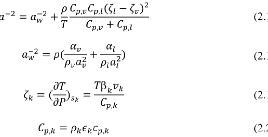
𝑎−2= 𝑎𝑤−2+ 𝜌 𝑇 𝐶𝑝,𝑣𝐶𝑝,𝑙(𝜁𝑙− 𝜁𝑣)2 𝐶𝑝,𝑣+ 𝐶𝑝,𝑙 (2.17) 𝑎𝑤−2 = 𝜌( 𝛼𝑣 𝜌𝑣𝑎𝑣2 + 𝛼𝑙 𝜌𝑙𝑎𝑙2) (2.18) 𝜁𝑘 = ( 𝜕𝑇 𝜕𝑃)𝑠𝑘 = 𝑇𝑘𝑣𝑘 𝐶𝑝,𝑘 (2.19) 𝐶𝑝,𝑘= 𝜌𝑘𝜖𝑘𝑐𝑝,𝑘 (2.20)
where k refers to each phase. Figure 2.6 shows the velocity of sound used in different papers in terms of the void fraction for CO2 at a pressure of 3682.9 kPa.
Figure 2.6 Sound velocity of two-phase CO2 as a function of the void fraction
2.9 Choking phenomena in the ejector
According to Keenan et al.’s [20] assumption, the two streams mix together inside the suction chamber and the mixing pressure is constant from the nozzle exit to the inlet of the constant area. However, this theory is unable to analyze the choking of the secondary flow under the critical operating mode. 0 50 100 150 200 250 300 0 0.2 0.4 0.6 0.8 1 Sound veloc it y (m /s) Void fraction CO2, P=3682.9 kPa Nakagawa et al. (2008) Zheng et al. (2015) Ameur et al.(2014) Angielczyk et al.(2010) Wood (1964)
2.10. Transcritical CO2 ejector expansion work recovery systems 14 Munday and Bagster [23] further assumed a constant pressure mixing in which the primary flow expands after exiting from the primary nozzle. It creates a hypothetical throat area (effective area) for the secondary flow downstream of the nozzle exit (Figure 2.7, section y-y) where the secondary flow reaches a sonic velocity and chocks at this point. After the choking of the secondary flow, the mixing process of the two streams starts and completes at the end of the mixing chamber. Due to the supersonic flow downstream of the mixing section, there is a train of shock waves that cause a compression effect and a sudden drop in flow speed.
Figure 2.7 Structure of the ejector used by Munday and Bagster [23]
Huang et al. [24] introduced a critical mode model for an ideal gas based on Munday and Bagster's [23] model. According to their model, there are two choking phenomena in the ejector; one in the primary flow through the primary nozzle throat and the other in the secondary flow, which is the result of the acceleration of the entrained flow from its stagnation point. Detail information about the critical mode of the ejector and its effect on the ejector modeling are presented in chapter 4 (Figure 4.3).
2.10 Transcritical CO
2ejector expansion work recovery systems
Nowadays, it is very important to recover waste heat and transfer it to useful energy (heating, cooling, etc.). A heat pump system provides heat by transferring it from one area to another (or lower temperature level to a higher temperature level). It is used for heat recovery from different sources in various industrial and residential applications to improve energy efficiency. In a subcritical heat pump, the low critical temperature reduces the performance and heat capacity of the system due to the limitation of the operating temperature range and low enthalpy of the vaporization at a temperature less or near the critical temperature [4]. Since CO2 can operate in a transcritical system due to high working pressure, CO2 heat pumps can work at a higher pressure than most other refrigerants. It has an advantage of high vapor density and high volumetric heating capacity, which causes the same heating capacity as other working fluids is obtained by a smaller volume of CO2. This results in a smaller and more compact system. A review study of transcritical CO2 refrigeration systems for supermarket applications was carried out by Gullo et al. [48]. A
transcritical two-phase ejector integrated into a refrigeration or heat pump cycle is used to improve the system performance by recovering some part of the expansion losses.
In 2003, a Japanese corporation (Denso) introduced a patent employing two-phase ejector in a transcritical CO2 heat pump and introduced it to the market [49]. Nowadays their heat pumps are manufactured by several companies. Though the first commercial applications have been introduced to the market [50], there is still a need to work in the field of ejector technology in the future. Recent ejector researches focused on the development of advanced models, investigation of alternative ejector cycles, applications of ejector work recovery cycles in real systems and control strategies [50].
Ju et al. [51] developed a simple thermodynamic CO2 ejector model for analyzing operating conditions in a CO2 heat pump water heater. They used a two-phase model with constant mixing pressure and obtained 16% higher COP than a conventional system. The ejector entropy production was found 22% of the total entropy of the system that indicated the importance of a good design of the ejector in such a system.
A simultaneous heating and cooling application was investigated by Sarkar et al. [52]. They developed a transcritical CO2 heat pump model to study the effects of the compressor speed, the inlet temperature of the external fluids to the evaporator and the gas cooler, the discharge pressure of the compressor and heat transfer area ratio on the COP of a heat pump system. The established results offered the guidelines for the design and optimization of a heat pump system. In a further investigation, Sarkar [16] developed a thermodynamic model with an ejector constant area mixing model for the optimization of two different cycles: a standard ejector expansion transcritical CO2 heat pump cycle and a modified cycle that feeds back some part of the separator vapor to the evaporator. The optimization was based on COP maximization for simultaneous cooling and heating applications. It was found that both cycles had similar results except at low evaporator temperatures where the modified cycle was less efficient. The results also showed the more significant effect of the gas cooler outlet temperature than the evaporator temperature on the performance of the cycle.
There are limited works on the effect of the ejector geometry using CO2 in the literature. Elbel and Hrnjak [27] conducted an experimental study of a transcritical CO2 ejector refrigeration system using a variable motive nozzle throat and compared the results with conventional expansion valve system under different ejector’s diffuser angle, high side pressures and ambient outdoor temperature. Their results showed an increase in both cooling capacity and COP up to 8% and 7% respectively in the ejector system. The COP was maximized at an optimum gas cooler pressure, however, the maximum ejector efficiency occurred at a pressure much lower than this optimum gas cooler pressure. The highest ejector efficiency was obtained at the smallest diffuser angle of 5˚. It was justified by a trade-off between kinetic energy losses by vortex formation in larger diffuser angles and frictional pressure drop losses in smaller diffuser angles.
The effect of the mixing length on the performance of a two-phase CO2 ejector refrigeration cycle was investigated by Nakagawa et al. [40] with and without internal heat exchanger (IHX). They used an ejector with a constant rectangular cross-section and three different mixing lengths (5, 15 and 25mm). The ejector efficiency and COP exhibited a minimum value for 5 mm and a maximum value for 15 mm. However, increasing the length of the mixing section had a negative effect on
2.10. Transcritical CO2 ejector expansion work recovery systems 16 COP. The COP was improved by up to 26% with IHX using the 15 mm length. However, increasing further the mixing length lowered the COP by 10%.
Nakagawa et al. [53] experimentally investigated the two-phase flows of CO2 in the diverging part of a rectangular converging-diverging nozzle to analyze decompression boiling process for different angles and inlet conditions. They proved that the pressure distribution curve approached the calculated isentropic homogeneous equilibrium (IHE) curve for divergence angles larger than 0.306˚ with high inlet temperatures above 35˚C. However, for divergence angles smaller than 0.306˚ and inlet temperatures below 35˚C, the pressure distribution was different from that calculated by IHE which indicated that the boiling process occurred at non-equilibrium state. Angielczyk et al. [54] developed the homogeneous relaxation model (HRM) for a two-phase CO2 flow through the ejector motive nozzle. The pressure distribution along the nozzle was calculated for three different nozzle geometries and compared with experimental data of Nakagawa et al. [53]. The model was more consistent than the homogeneous equilibrium model (HEM) in terms of propagation velocity and therefore speed of sound prediction. Even though their results were in agreement with experiments downstream the throat, they could not validate their model upstream and in the nozzle throat.
Yazdani et al. [43] presented a non-homogeneous mixture model for CO2 two-phase flows inside an ejector. A commercial CFD platform was implemented to formulate the conservation equations of mass, momentum, and energy for the mixture density and mass averaged velocity. The phase-change model was also used to account for the non-equilibrium transition to a two-phase regime. The evaporation/condensation rate was obtained from the dynamics of bubble growth including boiling and cavitation. The results showed that the cavitation portion of phase change was generally small but could be dominant near the walls and at the motive nozzle throat. The slip model was recognized to be not efficient to predict the overall ejector performance.
Palacz et al. [55] studied the accuracy of homogeneous equilibrium model using CFD based on the expansion of CO2 through two-phase ejectors for a vast range of ejector operating conditions. The experimental tests were carried out for the validation of the simulated results in terms of mass flow rates. It was concluded that the accuracy of the HEM varied for different operating conditions. The results were more accurate for operating conditions close to or above the critical point of CO2. Moreover, with the decreasing temperature and decreasing distance to the saturation line, the model accuracy decreased.
Smolka et al. [17] developed a homogeneous model of CO2 two-phase flow. A robust numerical solution was developed to simulate the two-phase flow with real gas properties compared with well-known multi-phase models, such as the Euler–Euler or the mixture models. An enthalpy based equation (instead of temperature based) was used in the mathematical model. Local pressure distributions in the mixing chamber and diffuser and the mass flow rates of primary and secondary flows were obtained and validated with the experiments. It was reported that heterogeneous model was unstable with unacceptable computation times. This model was then used by Palacz et al. [41] to optimize a CO2 ejector mixing section. They used two optimization algorithms, a genetic algorithm (GA) and an evolutionary algorithm (EA) to optimize a CO2 ejector mixing section. The optimization was based on maximizing the ejector efficiency. The result demonstrated the high
relation between ejector performance and mixing section diameter as the larger length of the mixing section was obtained in the optimal design.
More complicated models (heterogeneous considering phase change such as evaporation/ condensation) may give more details of the two-phase flow nature but they are computationally too expensive for optimization purpose.
2.11 Nomenclature
Subscripts
A Cross section area, mm2 d Diffuser
a Sound velocity, m s-1 e Exit
cp Specific heat, J kg-1 K-1 ejec Ejector
ER Entrainment ratio in Inlet
h Specific enthalpy, kJ kg-1 is Isentropic
𝑚̇ Mass flow rate, kg s-1 l Liquid
M Mach number max Maximum
P Pressure, kPa mix Mixing
Pratio Pressure ratio (pressure lift) p Primary s Specific entropy, kJ kg-1 K-1 rec Recovery
u Velocity, m s-1 s Secondary
V Volume, m3 th Ejector throat
W Work rate, kW tot Total
Greek symbols v Vapor
α Volume void fraction Abbreviation
Thermal expansion coefficient, K-1 1-D One dimentional
ϵ Interacting fraction CFD Computational fluid dynamics
η efficiency COP Coefficient of performance
Chemical potential, J kg-1 HEM Homogeneous equilibrium model
ρ Density, kg/m3 HRM Homogeneous relaxation model
𝑣 Specific volume, m3 kg-1 IHE Isentropic homogeneous equilibrium
𝑥 Quality IHX Internal heat exchanger
18
ENERGY
AND
EXERGY
EFFICIENCIES
OF
DIFFERENT CONFIGURATIONS OF THE
EJECTOR-BASED CO
2REFRIGERATION SYSTEMS
3.1 Avant-propos
Auteurs et affiliation:
• Sahar Taslimi Taleghani: étudiante au doctorat, Université de Sherbrooke, Faculté de génie, Département de génie mécanique.
• Mikhail Sorin: professeur, Université de Sherbrooke, Faculté de génie, Département de génie mécanique.
• Sébastien Poncet: professeur, Université de Sherbrooke, Faculté de génie, Département de génie mécanique
Date d’acceptation: 1 Janvier 2018
État de l’acceptation: version finale publiée.
Revue: International Journal of Energy Production and Management
Titre français: Efficacités énergétiques et exergétiques des différentes configurations de systèmes frigorifiques à base d'éjecteur au CO2
Contribution au document: Cet article contribue à la thèse en comparant différents cycles d'éjecteurs au CO2 transcritiques afin de trouver le cycle le plus efficace du point de vue thermodynamique.
Résumé français: Le dioxyde de carbone (CO2) est un remplacement approprié aux réfrigérants classiques en raison de ses faibles effets sur le réchauffement de la planète. Cependant, son application dans un cycle traditionnel de réfrigération par compression conduit à de faibles performances thermodynamiques en raison des pertes de dilatation importantes dans un processus d'étranglement. L’utilisation d'éjecteurs permet de réduire ces pertes. De nombreux scénarios de cycles basés sur des éjecteurs ont été proposés. Parmi eux, quatre configurations différentes peuvent être distinguées: un cycle de récupération du travail d'expansion (EERC), un cycle de recirculation des liquides (LRC), un cycle croissant de pression de décharge du compresseur (CDPC) et un cycle de réfrigération à jet de vapeur (VJRC). Cette étude traite de l'analyse comparative de ces cycles. Afin d'étudier les performances des cycles, les simulations numériques sont développées à l'aide du logiciel EES. Deux critères de performance, l'efficacité énergétique (COP) et l'efficacité exergétique sont évalués pour chaque cycle. Les valeurs les plus élevées de
ces critères indiquent le cycle le plus efficace du point de vue thermodynamique. Les résultats montrent que l’EERC présente l’efficacité la plus élevée en matière de COP et d’exergie par rapport aux autres cycles. Par exemple, le COP de l'EERC est 3.618 et l'efficacité énergétique est de 9.68%. Le COP (resp. efficacité exergétique) est d'environ 23.3% (resp. 23.3%), 24,9% (resp. 25.5%) et 5.6 fois (resp. 56.2%) supérieur aux rendements énergétiques et exergétiques correspondants aux cycles LRC, CDPC et VJRC. De plus, en comparaison avec un cycle basique, le COP et l'efficacité exergétique de l’EERC sont supérieurs de 23% et 24% respectivement. L'analyse exergétique détaillée du cycle EERC a permis de localiser les composants où se produisent les principales pertes exergétiques. Les pertes les plus importantes se produisent dans l’évaporateur (environ 33% de la destruction totale de l’exergie du cycle), suivi par le compresseur (25.5%) et l’éjecteur (24.4%).
3.2 Abstract
Carbon dioxide (CO2) is an appropriate replacement for conventional refrigerants due to its low global warming effects. However, its application within a traditional refrigeration compression cycle leads to low thermodynamic performance due to the large expansion losses in a throttling process. The application of ejectors allows reducing these losses. Many scenarios of ejector-based cycles have been proposed. Among them, four different configurations may be distinguished: an expansion work recovery cycle (EERC), a liquid recirculation cycle (LRC), an increasing compressor discharge pressure cycle (CDPC) and a vapor jet refrigeration cycle (VJRC). This study deals with the comparative analysis of these cycles. In order to study the performance of the cycles, the numerical simulations are developed using EES software. Two performance criteria, energy efficiency (COP) and exergy efficiency are evaluated for each cycle. The highest values of these criteria point to the most thermodynamically efficient cycle. The results show that the EERC has the highest COP and exergy efficiency compared to other cycles. For example, the COP of the EERC is 3.618 and the exergy efficiency is 9.68%. The COP (resp. exergy efficiency) is approximately 23.3% (resp. 23.3%), 24.9% (resp. 25.5%) and 5.6 times (resp. 56.2%) higher than the corresponding energy and exergy efficiencies of LRC, CDPC and VJRC. Moreover, in comparison with a basic throttling valve cycle, the COP and exergy efficiency in EERC are higher up to 23% and 24% correspondingly. The detailed exergy analysis of EERC cycle has pinpointed the equipment where the major exergy losses take place. The largest losses occur in the evaporator (about 33% of the total exergy destruction of the cycle) followed by the compressor (25.5%) and the ejector (24.4%).
3.3 Introduction
Carbon dioxide (CO2) is an appropriate replacement for conventional refrigerants due to its low global warming effects. One of the disadvantages of the cycle is a large exergy loss due to an important pressure reduction during expansion of CO2 from the supercritical to the subcritical state in a throttling valve. Among different devices for expansion work recovery, ejector is a favorable equipment, which enables to reduce losses by recovering part of the expansion work in a throttling process and improve the cycle’s efficiency.
The first application of two-phase ejector to the transcritical CO2 cycle was first described by Gay [56]. It was proposed to replace the expansion valve by a two-phase ejector to reduce the losses due to the throttling process.
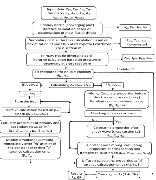
![Figure 2.7 Structure of the ejector used by Munday and Bagster [23]](https://thumb-eu.123doks.com/thumbv2/123doknet/2696575.62919/28.918.160.752.277.505/figure-structure-ejector-used-munday-bagster.webp)

![Figure 4.2. Transcritical CO2 cycle and corresponding temperature-specific entropy diagram Li and Groll [7] employed a two-phase ejector model based on the Kornhauser’s model for a transcritical CO2 air-conditioning system](https://thumb-eu.123doks.com/thumbv2/123doknet/2696575.62919/49.918.132.791.106.367/transcritical-corresponding-temperature-specific-employed-kornhauser-transcritical-conditioning.webp)