Science Arts & Métiers (SAM)
is an open access repository that collects the work of Arts et Métiers Institute of Technology researchers and makes it freely available over the web where possible.
This is an author-deposited version published in: https://sam.ensam.eu Handle ID: .http://hdl.handle.net/10985/11836
To cite this version :
Ali LAHOUEL, Saïd BOUDEBANE, Alain IOST, Alex MONTAGNE - A new method to fabricate Fe-TiC composite using conventional sintering and steam hammer - International Journal of Engineering Research in Africa - Vol. 29, p.28-44 - 2017
Any correspondence concerning this service should be sent to the repository Administrator : [email protected]
Science Arts & Métiers (SAM)
is an open access repository that collects the work of Arts et Métiers ParisTech researchers and makes it freely available over the web where possible.
This is an author-deposited version published in: http://sam.ensam.eu Handle ID: .http://hdl.handle.net/null
To cite this version :
Ali LAHOUEL, Said BOUDEBANE, Alain IOST, Alex MONTAGNE - A New Method to Fabricate Fe-TiC Composite Using Conventional Sintering and Steam Hammer - International Journal of Engineering Research in Africa - Vol. 29, p.28-44 - 2017
Any correspondence concerning this service should be sent to the repository Administrator : [email protected]
A New Method to Fabricate Fe-TiC Composite Using Conventional
Sintering and Steam Hammer
Ali Lahouel
1,a*, Said Boudebane
1,b, Alain Iost
2,c, Alex Montagne
2,d1
Department and Laboratory of Metallurgy and Engineering Materials, BADJI Mokhtar-University, P.O. Box 12, 23000 Annaba, Algeria
2
Laboratory of MSMP, Arts et Metiers ParisTech, 8 Louis XIV Street, 59046 Lille Cedex, France
a
[email protected], [email protected], [email protected],
d
Keywords: Composite, Fe-TiC, Sintering, Forging, Steam Hammer, Relative density,
Microstructure, Alloying additives, Powder Metallurgy.
Abstract: The aim of this research paper is to fabricate a Fe-TiC composite by a novel and simple
manufacturing method. The latter is based on two cumulative processes; a conventional sintering (transient liquid phase sintering) and a hot forging with steam hammer respectively. The blinder phase of the studied simples is varied from carbon steel to high alloy steel using alloying additive powders. The obtained outcomes showed that after the sintering process, the relative density of the performed simples is improved from 86% to 95.8% without any densification process. Otherwise, in order to ensure maximum densification and enhance in addition the solubility of the alloying additives the hot forging process is then applied. Indeed, the final obtained composite product is a TiC-strengthened steel with a relative density around 99% (about 6.5 g/cm3 of density) wherein 30% (wt.) of spherical and semi-spherical TiC particles are homogeneously distributed in the metal matrix.
Introduction
Nowadays the Metal Matrix Composites (MMCs) are recognized as advanced materials as they are being used successfully in a wide range of applications such as ground transportation, aerospace and automotive, etc [1]. These materials consist of a metal matrix in which nonmetallic reinforcements such as particles, fibers, and whiskers are dispersed [2]. For instance, Titanium carbide (TiC) has been recognized as one of the most important reinforcing phase especially in the Fe-base composite due to its excellent properties [3]. Indeed, the incorporation of the TiC particles into ferrous matrix lead to the increasing of wear and corrosion resistance, thermal and chemical stability, modulus of elasticity, as well as shearing and creep of the Fe-TiC composite [4-6].
Many products, such as FERROTiC, TiCALLOY, and FERRO-TITANIT, have been developed and commercialized [7]. The synthesis routs of Fe-TiC composites are classified in two main groups including molten and solid state. Conventional melting and casting are carried out in the molten state. These technics are applied for shaping large and complex shapes due to their flexibility. Regarding the solid state, powder metallurgy (PM), self-propagating, high-temperature synthesis (SHS), mechanical alloying, carbothermal reaction, and thermite reduction are the most performed routes [8-10]. Among all these stated technics, it is worth noting that for a uniform distribution of the TiC particles in the metal matrix of the Fe-TiC composite, Powder metallurgy is the frequently used. However residual porosity could be occurred in the final composite product which decreases its mechanical properties [11, 12]. To tackle this problem common processing routes for powder metallurgy to fabricate a Fe-TiC composite with very low porosity are developed in the literature; extrusion, forging, rolling and hot isostatic pressing (HIP) [1, 13].In this context, to produce a Fe-TiC composite with a very low porosity and TiC particles homogeneously distributed in the metal matrix, a new and simple manufacturing method is herein presented. This method consists of two cumulative processes; a conventional sintering and a hot forging with steam hammer respectively. This investigation was started by studying the influence of the alloying
additive on the relative density after the conventional sintering process by increasing the chromium content. The hot forging is then used to ensure maximum densification of the sintered preforms using a steam hammer. The relative density, microstructure, diffusion of the alloying additives, morphology and distribution of TiC particle, are also discussed.
Experimental Procedure
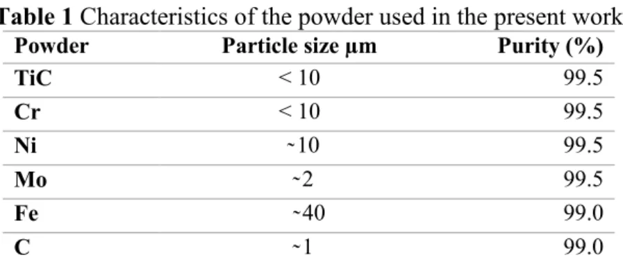
Preparation of the green compact. The characteristics of the powder used in the present work are
listed in Table 1. The samples (green compacts) were prepared as following: the initial components were mixed for 30 min using stainless steel balls, and dried after that in a furnace during 8h at about 80C° to remove adsorbed water.
Table 1 Characteristics of the powder used in the present work
Powder Particle size µm Purity (%)
TiC < 10 99.5 Cr < 10 99.5 Ni ̴ 10 99.5 Mo ̴ 2 99.5 Fe ̴ 40 99.0 C ̴ 1 99.0
Table 2 presents the composition of the prepared samples which are devised as follows:
1. Group 1: Pellets, of 13mm diameter with a weight of 5.0g were compacted under uniaxial pressure of 740 Mpa in a tungsten carbide die with 79% as average green density (aspect ratio 2:1)
2. Group 2: Pellets, 29mm diameter with a weight of 40g were compacted under uniaxial pressure of 163 Mpa in a tungsten carbide die with 67% as average green density (aspect ratio 2:1)
Table 2 Chemical compositions of the green mixture (wt.%)
The blinder phase Reinforcement
Samples Cr Mo Ni C Fe TiC Group1 Group 2 C0 FC0 - - - 0.65 Balance 30 C1 FC2 3 2 5 0.65 Balance 30 C2 - 9 2 5 0.65 Balance 30 C3 FC3 13 2 5 0.65 Balance 30 C4 - 19 2 5 0.65 Balance 30
From the table above, there are two kind of chemical compositions:
• in both groups, there is a reference composition (C0, FC0) which does not contain any alloying additives where the TiC particles are bounded by a carbon steel matrix [30% TiC + (0.65% C + Fe)]
• the other compositions are with alloying additives where there is a change in the chromium content (3 to 19%), known that the TiC particles are bounded by a high alloy steel matrix. It is worth noting that both groups were sintered. Whereas only samples of the 2nd group were then hot forged.
The developed methodology. The production of our composite (Fe-TiC) is firstly performed on the
base of the conventional powder metallurgy technic of cold compacting and sintering. Subsequently, the sintered samples are forged to the density level of wrought materials [13]. Hereinafter, both processes are presented in details.
Sintering process. The green compacts are high temperature sintered in a primary vacuum
environment (10-3 Mba) at 1500 C° for 30 min. The reached temperature is just below the melting point of the base metal (Fe), which means that the volume diffusion and the viscous flow are intense. Moreover, the presence of Ni and Cr elements creates a liquid phase at 1345 C° according to the diagram Cr-Ni diagram [14]. However the proportion of the liquid phase is increased with the additions of the chromium content due to the increasing of the contact area between particles of Cr and Ni elements. When this liquid phase attained its limit of solubility into the ferrous matrix, it will eventually disappear again according to the ternary diagram Fe-Cr-Ni (X%Cr 5%Ni and Fe), which presents the behavior of a transient liquid phase sintering. Consequently, the densification mechanisms are accelerated.
Closed die forging. In this process, we heated the samples at 1250 C° in a protective environment to
prevent oxidation. Then, we forged the samples on their both faces in an appropriate die by ten strokes using a steam hammer with a load of 50 Kgs at 30cm of high (Fig. 1). The presence of porosity improves the forgeability of the composite during the dynamic flow caused by the plastic deformation under the falling weight of the steam hammer at 1250 C°. In addition, the dynamic flow of the material during the hot forging enhances the solubility of the alloying additives.
Fig. 1 Steam hammer forging
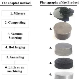
Next, the forged samples are annealed at 1050 C° for 2 hours in a vacuum environment. The flow-chart of the adopted manufacturing method is illustrated in Fig. 2.
Measurement. The bulk densities of the samples were measured by Archimedes’ method using
distilled water as medium. On the basis of three measurements, on three separated samples, the average relative densities and the standard deviations for all deemed materials are calculated. The relative density is defined as the measured density divided by an estimated theoretical density. This latter was estimated using rule of mixture among the densities of TiC and other elements.
Microstructural analyses of the composite product are performed by mean of Scanning Electron Microscopy (SEM). EDS mapping and Energy Dispersive X-ray Spectroscopy (EDS) are used to map the diffusion of the alloying additives. Additionally, Image analysis using ImageJ is used to analyze the distribution, dispersion and the average particles size of the TiC particles.
Results and discussion
Relative density analysis. Generally, in powder metallurgy, the relative density can be affected by
several processing variables such as green density, sintering temperature and time, alloying additions, particle size of the initial powders[12] as well as the additional densification process (hot forging) which is the most pertinent parameter in our case of study. As already indicated, this investigation is started by studying the influence of the alloying additives on the relative density after the sintering process. In this context, Figure 3 illustrates the relative density of the samples from the first group, where the relative density increases respectively with the additions of the chromium contents in C1, C2, C3, C4 samples
Fig. 3 The relative density of samples of the 1st group
As shown in Fig. 3 the sample C0 (without alloying additive), had the lowest relative density 86%, which however remains higher than the green density (79%). This densification is mainly due to the progress of the transfer mechanisms of the material between the matrix’s particles during sintering. This can be explained by the high intensity the volume diffusion processes and the viscous flow at 1500 C°.
Fig. 4 Photograph of the green compact before sintering
80% 82% 84% 86% 88% 90% 92% 94% 96% 98% C0 C1 C2 C3 C4 R e la ti v e d e n s ity Samples 2nd Group 1st Group
It can be seen from the same figure (Fig. 3) that the relative density grows from 86% (C0) to 89% (C1) with the alloying addition. In this stage, the densification is more accelerated because the presence of the liquid phase during sintering formed between alloying additives. When the chromium content increases from 3% to 9%, we observed that the largest difference in relative density is from 89% (C1) to 93% (C2). Therefore, we can say that the relative density increased by the increasing of the chromium content, wherein the main reason behind this phenomenon is related to the behavior of liquid phase sintering. In this process, the additions of the chromium content increase the proportion of liquid phase according to Cr-Ni phase diagram [14]. The presence of these two elements (Ni and Cr) can form a eutectic at 1345 C°.
The liquid phase sintering accelerates diffusion in the iron matrix, where alloying takes place between liquid and solid phase, and if the proportion of the liquid phase is smaller than its solubility in the iron matrix, the liquid phase eventually disappears[15] as well as diffusion continues in the solid state. The result is a significant reduction in porosity between particles.
Once again, from Fig. 3, the lowest porosity is observed at 13% Cr (C3) and 19% Cr (C4) wherein their relative densities are close to each other (95.2% and 95.8% respectively). From the exposed above, it can be concluded that the densification using chromium is achievable but it is limited to 95.8% for this sample group.
The presence of porosity can affect and decrease microstructural and mechanical proprieties [11]. Nevertheless, many previous works showed how to produce a full density composites such as TiC-strengthened steel based on various technics. For instance, conventional melting and casting, in-situ production of dispersions, powder metallurgy by hot isostatic pressing (HIP) [1]. Among these, Powder forging made by the conventional press and sinter method has been widely adopted due to its economic cost advantage [13]. In the present work, we used a steam hammer to forge the sintered samples after new heating of forging temperature.
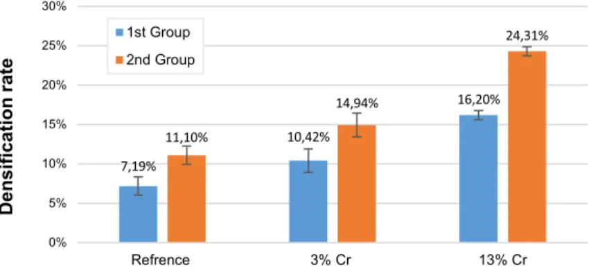
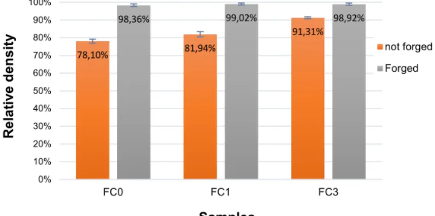
In order to eliminate the porosity from the sintered samples, three chemical compositions (FC0, FC1, FC3) are chosen to be forged by a steam hammer. These compositions are similar to those samples of the first group (C0, C1 and C3 respectively) but in this time with different dimension, weight and relative density, known that this latter is related to the load limitation of the hydraulic press used to compact the mixed powder. It is worth noting that the motivational reason to perform the FC0, FC1 and FC3 samples (Table 2), is that the samples of the first group (C0, C1 and C3) quickly lose their heat and can not be forged due to their small size in the die of our steam hammer. In this context, after the sintering process, the relative density of FC0, FC1 and FC3 samples were 78.10%, 81.94% and 91.31% respectively (Fig. 6) and their green density was 67%. Despite the surface contact between particles in the green compacts is reduced in this group compared with the first group (79% of green density), the densification rate after sintering were more important as can be concluded from Fig. 5. In our point of view, this may be related to the load applied by the weight of the sample on itself (40g) at 1500 C° wherein the temperature of base metal (Fe) was too close to its melting point, and therefore, the volume diffusion and the viscous flow mechanism are more accelerated under its own weight.
Fig. 5 Densification rate after sintering of samples with the some chemical composition from the
two groups 7,19% 10,42% 16,20% 11,10% 14,94% 24,31% 0% 5% 10% 15% 20% 25% 30% Refrence 3% Cr 13% Cr D e n s ifi c a ti o n r a te samples 1st Group 2nd Group
Forging is carried out with a steam hammer at 1250 C° under 50 Kgs of falling weight at 30 cm of high. This process is characterized by the simultaneous effect of dynamic load, high velocity and heat on the porous preforms. Hereafter Fig. 6 illustrates the relative density of the 2nd group before and after forging.
Fig. 6 The relative density of samples of 2st group before and after forging
The above histogram shows in one hand, that the best forging densification is found in FC0 (reference sample) from 78.1% to 98.36%. On the other hand, the highest relative density is 99.02% for FC1 sample. In addition, the residual porosity of FC0, FC1 and FC3 are 1.64% 0.98% and 1.08% respectively. However, their relative density after hot forging are up to 98% which is near to the full density. This densification is related to the behavior of the plastic deformation of the metal matrix at 1250 C° under the effect of the dynamic load in the close die. During forging, samples have been subjected to isostatic compaction (falling weight of the steam hammer in a close die) which substantially reduced the porosity. Besides, vacuum sintering under 10-3Mba left pores with a very low pressure, which lead to their prompt elimination under the high pressing applied by the falling weight of the steam hammer.
Furthermore, during the forging process, the plastic deformation is the major densification mechanism. However, one of the greatest advantage of the powder forging process is that immensely improves forgeability of the powder metallurgy preforms compared to similar materials of full density. This improvement is directly related to the presence of porosity and the concomitant reduction in the strength of the preform [13]. Finally, it can be concluded, that despite the high porosity in the sintered samples of the second group (from 9% to 22%), using the steam hammer to forge these samples increases considerably the relative density to up to 98,36% (99,02% in FC1).
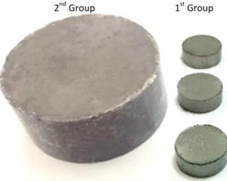
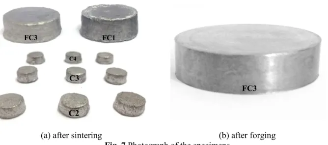
Final product. Fig. 7 illustrates a real photographs of the performed samples. The presence of the
liquid phase during the sintering process may cause a dimensional change of the sintered samples under the effect of gravity at high temperature as can be remarked from Fig. 7a. However, considerable shaping can be economically controlled by a die and isostatic compaction during a hot forging in order to obtain the wanted samples (see Fig. 7b). Moreover, Fe-base TiC composite has a special propriety which is the increase in machinability in the annealed condition. The obtained density of FC0, FC1 and FC3 after the hot forging are respectively 6.47, 6.55 and 6.48 g/cm3
78,10% 81,94% 91,31% 98,36% 99,02% 98,92% 0% 10% 20% 30% 40% 50% 60% 70% 80% 90% 100% FC0 FC1 FC3 R e la ti v e d e n s ity Samples not forged Forged
(a) after sintering (b) after forging
Fig. 7 Photograph of the specimens
Microstructure. The shape of porosity at the microstructural level can give us a better
understanding of which sintering mechanisms are performed during this process. Solid phase sintering produces samples with irregular shape pores, however spherical pores are the results of the presence of liquid phase during the sintering process [15].
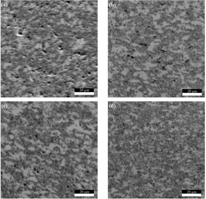
Fig. 8 presents the Scanning Electron Microscopy (SEM) micrographs of C0, C1, C2 and C3 samples (the first group). It is clear that the distribution of the pores, the matrix and TiC particles can be defined from these SEM micrographs. From Fig. 8a (reference sample without alloying additions, C0), it is clear to note that many pores of irregular shape with different size (small to big pores) are existing between the TiC particles, wherein the matrix’s powder grain boundaries are indefinite. This high porosity is caused by the weigh fraction of TiC particles (30% weight) which reduces the contact area between Fe particles, and consequently reduces diffusion. Besides, the absence of the solubility in the solid state between the iron and the TiC particles limits the diffusion only between the particles of the same nature as explained below:
• Fe - Fe (high Diffusion)
• Fe - TiC (absence of solubility)
• TiC -TiC (low temperature so low diffusion).
The same, powder grain boundaries are also indefinite from the SEM micrograph of the Fig. 8b (sample C1 with 3%Cr) where the pores with irregular shape are also apparent but less distributed on the surface (low porosity). Whereas, the SEM micrograph of the sample C2 with 9% of chromium (Fig. 8c) shows that the pores became more spherical and the porosity amount is decreased compared to the previous samples, fact that significantly improved the relative density. Finally, less spherical and small pores are observed from the last SEM micrograph of sample C3 with 13 % Cr (Fig. 8d).
From the above outcomes we can say, in one side, that the solid phase sintering explains the distribution and the geometry of the pores in sample C0, which decreased the relative density. On the other side, the reduction of porosity in C1, C2 and C3 samples is due to the behavior of the transient liquid phase in which more chromium increases the liquid volume. Consequently, bonding between particles as well as alloying processes are accelerated with the increasing of the liquid proportion. This led to the spheroidization of pores and explains the reduction of porosity with the additions of chromium contents (3%, 9%, 13%).
FC3 FC1
C4
C3
C2
Fig. 8 SEM micrographs of Fe-TiC composite (a) C0, (b) C1, (c) C2, (d) C3
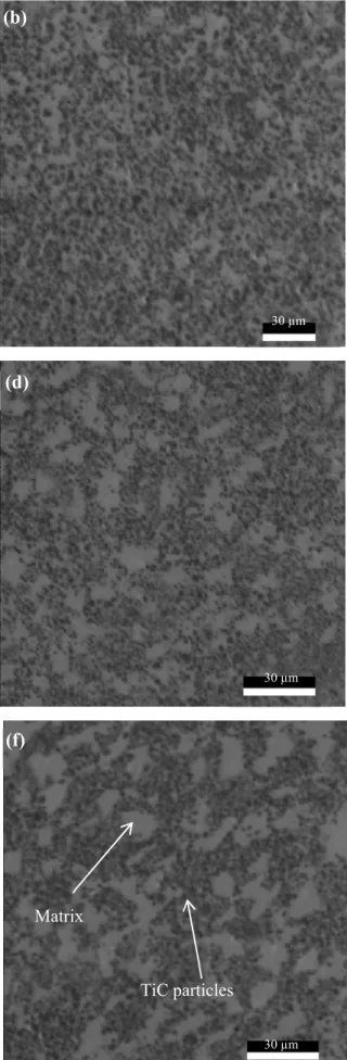
Fig. 9 illustrates a typical SEM microstructure of the three composites FC0, FC1 and FC3 (samples of the second group, which are manufactured by the adopted sinter forging method) reinforced with 30% weight of TiC particles. The dynamic flow and the plastic deformation of the metal matrix during the forging process results a new microstructure morphology characterized by the absence of porosity and a rearrangement of the TiC particles. This fact led to a better dispersion of the TiC in the blending phase (Fig. 9) compared with the sintered samples of the first group depicted in Fig. 8. (b) (c) (d) 20 µm 20 µm 20 µm 20 µm (a)
Fig. 9 SEM microstructure of groupe 2 after forging, FC0 (e,f) reference, FC1 (c,d) and FC3 (a,b)
From the Figs. 9(e, f) (FC0 the sample does not contain alloying additives), the TiC particles are uniformly distributed and no prior matrix particles boundaries are visible. Further, the TiC is bounded by the matrix particles and local agglomeration of TiC is found surrounding by the metal
(a) 100 µm 100 µm (b) (c) (d) (e) (f) 100 µm 30 µm 30 µm 30 µm Matrix TiC particles
matrix. In the composite FC1 with 3% Cr (Fig. 9c, d), the distribution of TiC particles are more uniform. However, this distribution is the best for the sample of 13% Cr (FC3, Fig. 9a, b).
Microstructural observations (Fig. 9) reveal that the forging process has eliminated the porosity by the plastic deformation and the viscous flow of the metal matrix caused by the dynamic load of the steam hammer at 1250 C°. Therefore, within the hot forging process, improvement in the microstructural properties and increasing in the relative density of the composite are reached which are considered the main aim of our research work.
Diffusion. In this study, the alloying elements pointed out in Table 2 were mixed and then have
been sinter-forged. Scanning Electron Microscopy (SEM) and Energy Dispersive X-ray Spectroscopy (EDS) were used to map the diffusion of the various alloying into the metal matrix of the FC3 sample with 13% Cr (Fig. 10a). These results allow a better understanding of the diffusion processes into the metal matrix especially in the presence of 30% TiC.
(b) (a) (d) (c)
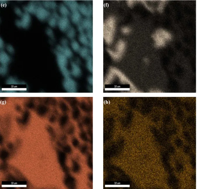
Fig. 10 EDS mapping of C (c), Mo (d), Ti (e), Cr, Fe (g) and Ni (h) of FC3 sample. (a) and (b) are
the micrograph and the global mapping
The EDS maps show that the C, Mo, Cr, and Ni are homogeneously distributed in the Iron-base matrix wherein the concentration of C and Ti is mainly found in the black particles, which presents the TiC. Around this latter, a high amount of the Mo element is concentrated, also Mo can be found into the TiC particles.
Chromium (Cr) concentration is intense in the residual ferrite (the gray area, Fig. 10a). The C and Mo are also well distributed in the residual ferrite, however, compared to the iron-base matrix their concentration is more important. The Nickel element is more diffused into the Iron-rich area compared to the residual ferrite.
The EDX spectrums illustrated in Fig.11 are taken from the residual ferrite, Iron base matrix, TiC particle and the interface TiC-Matrix. The results give about 6.43% Ni, 4.99% Cr and traces of Mo (0.06%) are deeper diffused into the Iron-rich area. The highest amount of Mo (1.18%) is found in the interface of the TiC-Iron matrix, and in addition, the residual ferrite is mainly formed between Fe element 64% and 26% of chromium. 1.18% and 1.31 of Ti element is found respectively in the Iron-rich area and the residual ferrite. Considering the previous results, we can consequently conclude that the microstructure is mainly formed between TiC bounded by the steel. More details about the chemical composition of different phases are presented in Table 3.
(e) (f)
Table 3 The chemical composition obtained with energy dispersive X-ray spectrometry (EDS) into
different phases
Elements wi
Iron-rich area Resudual Ferrite (b)
TiC (c)
Interface TiC-Iron matrix (d) (wt.%) (wt.%) (wt.%) (wt.%) (wt.%) C 2.55 6.26 16.17 15.99 Mo 0.06 0.11 0.48 1.18 Ti 1.18 1.31 77.48 48.09 Cr 4.99 26 0.69 10.7 Fe 84.78 63.84 4.88 23.28 Ni 6.43 2.49 0.29 0.75 (a) (b) (d) (c) (d)
Fig. 11 EDX spectrum of the (a) Residual ferrite (b) Iron-rich area (c) TiC particleand (d) intrface
TiC-Iron base matrix. (E) Sem image of differente phases
TiC distrubtion and image analysis. To further understand the morphology and the distribution of
the TiC particles into the iron-rich area and the residual ferrite phase, back-scattered electron micrograph was taken on FC1 (3% Cr) and FC3 (13% Cr). For that purpose, image analysis using ImageJ is processed to analyze the distribution of the TiC particles and evaluate their average size. Fig. 12 illustrates the morphology and the spatial distribution of the TiC particles as well as the residual ferrite phase into the metal matrix.
(a) (b)
Fig. 12 SEM Microstructures of FC1 (a,c) and FC2 (b,d) taken with back scattered electron
Back-scattered electrons provide micrographs that take into account the atomic weight of the chemical elements. Indeed, from Fig. 12 it is clear to note that the TiC particles are appeared in a gray color due to the high atomic weight of Ti element. Moreover, the high concentrations of the chromium in FC3 sample (26%) appears the residual ferrite phase in a lighter gray. Iron-rich area and residual ferrite phases are clearly visible in FC3 sample (Fig. 12b, d), where the residual ferrite is found accompanying with the agglomeration of TiC particles. However, this residual ferrite cannot be defined in FC1 sample with 3% of chromium (Cr) (Fig. 12a, c) and no prior high concentration of Cr element is found in this sample, which means that the 3% of chromium is homogeneously diffused in the matrix with the other additive elements.
Figs. 12c, d show that the TiC particles are more compacted in agglomerations in the FC1 sample compared with FC3. The microstructure of these Fe-TiC composites consisted of spherical and semi-spherical TiC particles where image analysis shows that their average size is 12.96 µm and 11.38 µm for FC1 and FC3 samples respectively. However, compared to FC1 samples (Fig.12c), TiC particles are more spherical in FC3 where we observed a degradation of the sharp angles of the ceramic particles (Fig. 12d), which is due to the dissolutions of TiC particles into the matrix. This proves that the liquid phase appeared during the sintering process, which is also confirmed by the presence of Ti element into the metal matrix from the EDS Spectrum (Table 3).
Image analysis of Figs. 13 show that TiC particles cover 41.67% and 42.03% of the surface in FC1 and FC3 samples respectively (Fig. 14). These results are too close to the volume fraction of TiC particles in these composites, which is about 41%. This fact confirm that the TiC particles are uniformly distributed into the metal matrix.
Fig. 13 Processed image represent the spatial distribution of TIC Particles of (a) FC1 and (b) FC3
Fig. 13 shows also that the TiC particles are found as agglomerations which are more compacted in FC1 (Fig. 13a) sample compared by FC3 (Fig. 13b). This fact led to a better dispersion of the TiC in FC3 with 13% Cr addition. The green compact of the second group contains 33% of porosity, which is generally concentrated between the TiC particles due to the incompressibility of these particles at room temperature. The arising liquid phase formed between Cr and Ni at 1345 C° is first being pulled by capillary forces into the narrow gaps between the TiC particles. In our opinion, the liquid flow redistributed the TiC particles and pushed them deeper into the iron particles, which led to a better dispersion of TiC particles.
(a) FC3 sample (b) FC1 sample
Fig. 14 Presents the proportion of TiC particles and the Residual ferrite on the surface Conclusion
In this study a new simple method to produce Fe-TiC composites with very low porosity is developed using a conventional sintering and a hot forging with steam hammer in a close die as an additional densification process. The obtained outcomes have revealed that the additions of the chromium element in the Nickel and Iron mixture promote the liquid phase during the sintering process at 1500C° by producing a transient liquid phase. This fact led to an important densification only in 30 min, wherein the highest relative density value reached after the sintering process was for the sample C4 (19% Cr) with 95.8%.
Regarding the forging process, the use of a steam hammer had a significant effect on the improvement of the relative density of the sintered samples. Indeed, the best relative density found in the present work through the application of the proposed manufacturing method was 99.02% for FC1 (6.55 g/cm3 of density). In this context, it can be concluded that the adopted forging process (using steam hammer in a close die) has the major function of material densification.
47% 42% 11% Metal Matrix TiC Residual Ferrite 58% 42% Metal matrix TiC (a) (b)
The robustness of the proposed method is then supported by the SEM micrograph and diffusion analysis, where the alloying additives are found completely diffused in the metal matrix of the studied samples. Moreover, about 30% (weight) of spherical and semi-spherical TiC particles are uniformly distributed in the metal matrix. Consequently, the adopted method to fabricate the Fe-TiC composite is indeed simple reliable and so efficiency.
Acknowledgments
This work was realized in collaboration with the laboratory of MSMP Material surfaces and Processing Materials, Art et Metiers ParisTech-Lille France. The authors wish to thank the director of the Laboratory, the authors are grateful to the professor ALAIN IOST, for Permitting to utilize the SEM facility.
References
[1] Parashivamurthy K, Kumar R, Seetharamu S, Chandrasekharaiah M. Review on TiC reinforced steel composites. Journal of materials science. 2001;36(18):4519-30.
[2] Firouzbakht A, Razavi M, Rahimipour MR. Synthesis of iron nanocomposite reinforced by TiC particles via mechanical activation from ilmenite concentrate and carbon black. Science and Engineering of Composite Materials. 2014;23(4):381–8.
[3] Ghosh B, Pradhan S. Microstructure characterization of nanocrystalline TiC synthesized by mechanical alloying. Materials Chemistry and Physics. 2010;120(2):537-45.
[4] Kattamis T, Suganuma T. Solidification processing and tribological behavior of particulate TiC-ferrous matrix composites. Materials Science and Engineering: A. 1990;128(2):241-52.
[5] Karantzalis A, Lekatou A, Georgatis E, Arni Z, Dracopoulos V. Solidification observations of vacuum arc melting processed Fe–Al–TiC composites: TiC precipitation mechanisms. Materials Characterization. 2011;62(12):1196-204.
[6] Pagounis E, Lindroos VK, Talvitie M. Influence of reinforcement volume fraction and size on the microstructure and abrasion wear resistance of hot Isostatic pressed white iron matrix composites. Metallurgical and Materials Transactions A. 1996;27(12):4171-81.
[7] Chen J-K, Tang T-P, Chan S-F, Chang S-H. Effects of particle size on mechanical properties of a TiC containing tool steel by hot isostatic press. Materials transactions. 2008;49(3):624-8.
[8] Zhang M, Hu Q, Huang B, Li J, Li J. Study of formation behavior of TiC in the Fe–Ti–C system during combustion synthesis. International Journal of Refractory Metals and Hard Materials. 2011;29(3):356-60.
[9] Razavi M, Yaghmaee MS, Rahimipour MR, Razavi-Tousi SS. The effect of production method on properties of Fe–TiC composite. International Journal of Mineral Processing. 2010;94(3):97-100.
[10] Sang-Hoon L, Jin-Ju P, Sung-Mo H, Byoung-Sun H, Min-Ku L, Chang-Kyu R. Fabrication of cast carbon steel with ultrafine TiC particles. Transactions of Nonferrous Metals Society of China. 2011;21:s54-s7.
[11] Kurgan N. Effect of porosity and density on the mechanical and microstructural properties of sintered 316L stainless steel implant materials. Materials & Design. 2014;55:235-41.
[12] Chawla N, Deng X, Marrucci M, Narasimhan K. Effect of Density on the Microstructure and Mechanical Behavior of Powder Metallurgy Fe-Mo-Ni Steels. Advances in Powder Metallurgy and Particulate Materials. 2003;6:7-257.
[13] Sutradhar G, Jha A, Kumar S. Production of sinter-forged components. Journal of Materials processing technology. 1994;41(2):143-69.
[14] Handbook A. Vol. 3: Alloy Phase Diagrams. ASM International, Materials Park, OH, USA. 1992:2.48.
[15] Kang S-JL. Sintering: densification, grain growth and microstructure: Butterworth-Heinemann; 2004.