Science Arts & Métiers (SAM)
is an open access repository that collects the work of Arts et Métiers Institute of
Technology researchers and makes it freely available over the web where possible.
This is an author-deposited version published in:
https://sam.ensam.eu
Handle ID: .
http://hdl.handle.net/10985/13316
To cite this version :
Romain GUIHEUX, Sophie BERVEILLER, Régis KUBLER, Denis BOUSCAUD, Etienne
PATOOR, Quentin PUYDT - Martensitic transformation induced by single shot peening in a
metastable austenitic stainless steel 301LN: Experiments and numerical simulation - Journal of
Materials Processing Technology n°249, p.339 - 349 - 2017
Any correspondence concerning this service should be sent to the repository
Science Arts & Métiers (SAM)
is an open access repository that collects the work of Arts et Métiers ParisTech
researchers and makes it freely available over the web where possible.
This is an author-deposited version published in:
http://sam.ensam.eu
Handle ID: .
http://hdl.handle.net/null
To cite this version :
Sophie BERVEILLER, Romain GUIHEUX, Denis BOUSCAUD, Etienne PATOOR, Régis
KUBLER, Quentin PUYDT - Martensitic transformation induced by single shot peening in a
metastable austenitic stainless steel 301LN: Experiments and numerical simulation - Journal of
Materials Processing Tech. n°249, p.339 - 349 - 2017
Any correspondence concerning this service should be sent to the repository
Martensitic transformation induced by single shot peening in a metastable
austenitic stainless steel 301LN: Experiments and numerical simulation
Romain Guiheux
a, Sophie Berveiller
a,⁎, Régis Kubler
b, Denis Bouscaud
a, Etienne Patoor
a,1,
Quentin Puydt
caArts et Métiers ParisTech, LEM3, 4, rue Augustin Fresnel, 57070 Metz, France
bArts et Métiers ParisTech, MSMP, 2 cours des Arts et Métiers, 13617 Aix-en-Provence, France cIRT M2P, 4, rue Augustin Fresnel, 57070 Metz, France
A B S T R A C T
During conventional shot peening on metastable austenitic steels, martensitic transformation occurs in addition to plastic straining. In this work, the impact of a single spherical steel shot on a AISI 301LN steel was studied. The volume fraction of martensite, residual stresses in both phases were determined in the vicinity of the dent as a function of the shot velocity and diameter. An elasto-plastic two phase model that includes martensitic phase transformation was adapted to model mechanical and microstructuralfields and implemented in Abaqus Explicit for the 2D simulation of a single shot impact. It was found, for instance, that the martensitic transformation takes place only under the dent and that martensite is in tension at the surface while austenite is in compression. Simulation results of stress levels showed a good agreement with experimental stresses determined by X-ray diffraction.
1. Introduction
Metastable austenitic stainless steels combine very good mechanical properties and high formability. They are good candidates for light-weight materials in automotive and other industrial sectors like energy and aviation. This remarkable combination of properties results from transformation induced plasticity. Formation of strain-induced mar-tensite during the deformation process increases the strength level of the material. Mechanical and structural components must exhibit high mechanical resistance and high formability, but also high fatigue re-sistance. Shot peening surface treatment is commonly used in me-chanical industry to increase fatigue resistance from the introduction of high compressive residual stresses that delays fatigue failure of com-ponent (Lillamand et al., 2001). Evaluation of these stresses is offirst importance to optimize component design and process parameters. The numerical simulation of the influence of shot-peening process on the internal stressfield distribution on the near surface is a useful but dif-ficult task because shot-penning is a complex process involving several mechanisms (Wohlfahrt, 1984). Numerous analytical models and nu-merical approaches based onfinite element analysis have been devel-oped to simulate the shot peening process and determine the relation-ships between process parameters, geometrical and material behavior
characteristics of the target and the resulting residual stressfield. Re-views of the wide variety of numerical models developed since thefirst simulation proposed byEdberg et al. (1995)can be found inRouhaud et al. (2005)and Sherafatnia et al. (2016). Analytical models allow determining the stress distribution and the depth of the affected zone but finite element simulations provide a better understanding of the process enabling parametric studies. Firstly, two-dimensional axisym-metricfinite element models were used to investigate the perpendicular impact of a single shot against an elastic-plastic surface (Mori et al., 1994; Schiffner and Droste gen. Helling, 1999). Three-dimensional model was later developed by Meguid et al. for single and multiple impacts (Meguid et al., 1999, 2002) and Guagliano found a way to relate the residual stressfield determined from finite element simula-tion to Almen intensity (Guagliano, 2001). A parametric study per-formed byMajzoobi et al. (2005)has investigated the influence of shot number and impact velocity on the residual stress profile, finding that the simulation of 25 impacts allows obtaining a uniform stress state. Influence of thermal effect resulting from plastic dissipation was es-tablished (Rouquette et al., 2009). Recent studies concentrated on the description of superficial shot peening damage (Frija et al., 2006), pe-ening treatment of rough surfaces (Yang et al., 2015) and effect of a pre-existing initial residual stress field on the residual stress field
distribution generated by shot peening (Mahmoudi et al., 2016). A re-view of the different symmetries and reference cell shapes used in the literature to reduce the computation time can be found inMiao et al. (2009). However, as shot peening involves a huge number of shots, finite element analysis fails to consider the particle dynamics inside the shot stream and its interactions with the target. Multiphase flow in computationalfluid dynamics was used to simulate the coverage under multiple impacts and overlapping indentations (Nguyen et al., 2014), but this approach provides no information about the induced residual stressfield. A semi-analytical approach was developed by Chaise et al. (2011&2012) to solve impacts problem and the plastic strainfield obtained was transferred to afinite element model to determine the residual stressfield in a peened thin structure. This eigenstrain method has been used for a long time in micromechanics and it appears also efficient for shot peening analysis as demonstrated by Musinski and
McDowell (2015) who used it for imposing shot–peened residual
stresses into a computational crystal plasticity framework.Hong et al. (2008)proposed a combined numerical analysis based onfinite element and discrete element methods. Such a coupling was used by Murugaratnam et al. (2015)to run an extensive parametric study, in-vestigate the coverage built-up and analyze energy transfer between the shot stream and the target surface. Based on this approach, a metho-dology was developed to simulate the process at minimal computing cost, determining representative elementary volumes for the target (Jebahi et al., 2016). Recently, the residual stress field due to shot peening was determined as a function of the process parameter within a gear tooth through the development of a dedicated software to de-termine the coverage and the velocity of the impacts on a mechanical component with complex geometry (Gallitelli et al., 2016).
The beneficial effect of shot peening on metastable austenitic steels was recently established byFargas et al. (2015), resulting in extensive austenite to martensite phase transformation. The residual stress state was obtained from the plastic incompatible strain imposed by the process and also from the strain-induced martensitic transformation. This phenomenon, called transformation-induced plasticity (TRIP), has beenfirst studied byOlson and Cohen (1982). It was established that martensite formation is influenced by strain rate (Hecker et al., 1982), temperature (Talonen and Hanninen, 2007) and the deformation mode
as tension and compression (Iwamoto et al., 1998), torsion (Lebedev and Kosarchuk, 2000), shear (Gallée et al., 2007) or bi-axial stress (Perdahcioglu et al., 2008). TRIP steels exhibit a multiphase micro-structure and internal stresses are generated during the phase transi-tion. This internal stress state is distributed among the different me-chanical constituents of the microstructure, producing a high level of stress heterogeneity inside the material (Berrahmoune et al., 2004). The occurrence of this solid-solid phase transformation and the coupling between plasticity and transformation-induced plasticity increase the level of complexity for the development of numerical simulation of industrial processes for these alloys. Large amount of works have been published about modeling of TRIP steel behavior and reviews can be found in (Fischlschweiger et al., 2012; Kubler et al., 2011). From a phenomenological point of view, two main problems have to be solved. Thefirst one corresponds to the determination of the transformation kinetics as a function of the control variables (stress, strain and tem-perature), and the second one to the determination of the overall be-haviour. About the former,Olson and Cohen (1975)have related the rate of transformation with plastic strain. This physically based model was extended byStringfellow et al. (1992)to include the influence of stress, byIwamoto et al. (1998)to get the triaxiality dependence and by Tomita and Iwamoto (1995)to take into consideration strain rate ef-fects. For the latter, in a seminal work Leblond et al. (1989) and
Leblond (1989) have used a continuum mechanics description,
as-suming the transformation strain rate follows the direction of the ap-plied deviatoric stress. A thermodynamically consistent model, in-cluding a full coupling between phase transformation and plasticity, was proposed by Fischer (1997) and extended by Levitas (1998)to consider finite deformation. Following the pioneering paper ofDiani et al. (1995)several works have considered the modeling of the TRIP behavior atfiner scales, using scale transition techniques to determine the macroscopic behavior. Among them,Cherkaoui et al. (1998, 2000) have developed micromechanical models based on the crystallographic theory of martensitic phase transformation.Gallée et al. (2007)have adapted models derived from the model ofLeblond et al. (1989)and Leblond (1989)or from the one ofStringfellow et al. (1992)such as Kubler et al. (2011)at the phase level using a meanfield approach to describe the behavior of a multiphase material. This last class of model Nomenclature
2a Diameter of the dent
δ Depth of the dent
Hb Height of the pile-up around the dent
Rc Curvature radius at the base of the dent
d Shot diameter
K Constant of the Johnson’s law
ρb Shot density
E* Equivalent Young’s modulus of both sample and shot Es, Eb Young’s modulus respectively of the sample and the shot
νs,νb Poisson’s ratio respectively of the sample and the shot
σθθ Stress component in the tangential direction with respect to the dent
σrr Stress component in the radial direction with respect to
the dent
f Volume fraction of martensite
A Austenite
a’ Martensite
E Total macroscopic strain tensor ε Elastoplastic local strain tensor ε Plastic local strain tensor ε Thermal local strain tensor
ϵT Transformation local strain tensor
ϵT Mean Instantaneous Transformation Strain (MITS) tensor
εeqp Von Mises equivalent local plastic strain according
lep Tangent elastoplastic local modulus tensor
m Thermal local modulus tensor ath Thermal expansion tensor
Σ Total macroscopic stress tensor σ Local stress tensor
S Deviatoric part of the local stress tensor σeq Equivalent stress of Von Mises
σ0 Initial yield stress
R Isotropic hardening coefficient p Cumulated plastic strain
Q0, b C, *, γ Material constants of the hardening law CC Elastic stiffness tensor
μ Shear coefficient
I Identity fourth order tensor
Ff Driving force for martensitic transformation Fc0 Critical force for martensitic transformation
V V
Δ Volume change associated with the martensitic transfor-mation
β, α, n, κ Material constants of the kinetics of martensitic transfor-mation
d1,d2 Material constants of the MITS
MITS Mean Instantaneous Transformation Strain RVE Representative Volume Element
demonstrated both a good accuracy for model prediction and reason-able computation cost. This class of model enreason-ables the numerical si-mulation of industrial processes like deep drawing of metastable aus-tenitic stainless steel as shown inGallée and Pilvin (2010)and inMsolli et al. (2016), or hydroforming of steel tube as inLindgren et al. (2010). In the present work, the approach initially developed byKubler et al. (2011)for forming problems is applied to thefinite elements simula-tions of single shot-peening.
To the knowledge of the authors, only few experimental studies have been published up to now dealing with the impact of shot peening on metastable austenitic steels. Kleber and Barroso (2010) have de-termined the evolution of residual stresses both in the martensitic and austenitic phases, and the martensite volume fraction for different shot-peening conditions on AISI 304L samples. They showed that the max-imum compressive stress was obtained at the depth where the mar-tensite volume fraction reaches its maximum.Turski et al. (2010)have performed microstructural observations and residual stress analysis in AISI 304L steel for different mechanical surface treatments including shot peening, showing evidence of deformation induced martensite in the near surface, extensive work hardening and isotropic in-plane re-sidual stress state within the austenitic phase.Fargas et al. (2015)have studied the effect of different shot-peening conditions in cold rolled and annealed AISI 301LN sheets. They showed that similar or lower fatigue limits were obtained for both specimens and that a pre-existing amount of martensite in the cold-rolled specimens slowed down the transfor-mation kinetics of martensite compared to annealed one. Fu et al. (2013)have studied the evolution of residual stresses both in the aus-tenitic and martensitic phases in the 18CrNiMo7-6 steel and showed that it was higher in the martensitic phase of higher yield strength. In 2016, using a large strain formulation of transformation plasticity, Halilovic et al. proposed the veryfirst numerical simulation of the re-sidual stress state in AISI 304 peened steel with a single laser shot (Halilovic et al., 2016). They concluded that at low temperature the residual stress state is mainly caused by phase transformation, and it is mainly due to plastic deformation at high temperature.
Therefore, in this paper, it is proposed to investigate, both experi-mentally and by numerical model, the effect of a single spherical normal shot on strain-induced martensitic transformation in AISI 301 LN samples at room temperature. Different shot velocities were studied. Microgeometry of the impact was measured. Martensite volume frac-tion and residual stress profiles in both phases around the impact were evaluated using X-ray diffraction. Experimental results were compared to two-dimensional axisymmetricfinite element simulations of a single shot impact. For the material behaviour, a semi-phenomenological model coupling the martensitic phase transformation and the elasto-plastic behavior of austenite and martensite was calibrated using quasi-static tensile tests and implemented in a user subroutine in ABAQUS Explicit. Finite element simulations were performed in the same ex-perimental conditions and results were compared with experiments. 2. Experiments
a. Experimental method
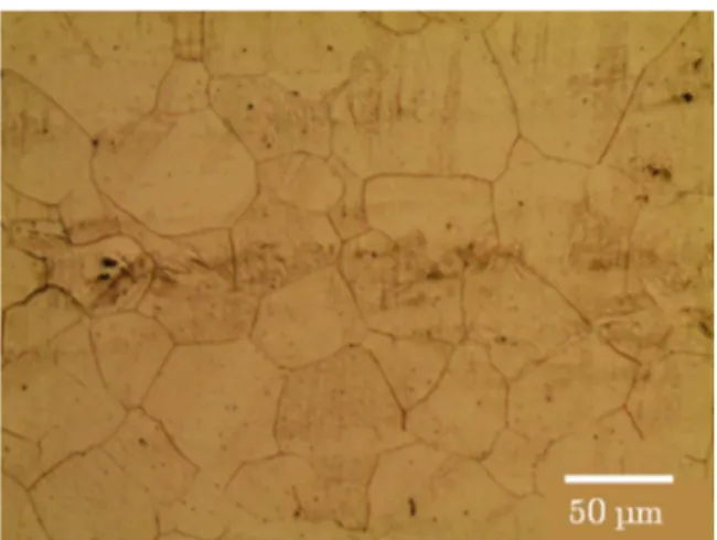
The studied material was a hot rolled AISI 301LN austenitic stainless steel supplied as sheets of 10 mm thick by Aperam; its chemical com-position (in weight percent) is the following: 0.019C-0.57Si-1.71Mn-6.60Ni-17.31Cr-0.108N-0.002S-0.030P. For microstructure observa-tion, the samples were mechanically polished and electro-polished with a solution of perchloric acid in order to eliminate the residual surface hardening. Electrolytical etching was performed using a solution of nitric acid (60 ml) and water (40 ml) during 30 s at 2 V. As shown Fig. 1, the initial microstructure is austenitic with a grain size of about 50 mm.
Single shot tests were performed on plates with dimensions of 75 mm × 75 mm × 8 mm. The sample surface was previously ground with 600–1200 grit paper, followed by successive polishing with of 6, 3
and 1 mm diamond suspension. Residual stress were determined before shot peening to ensure that polishing has not affected the surface, as described in Section 2c. Single shot peening was performed on a in-house device. A spherical steel (100Cr6) shot was projected from an air gun system oriented normal to the workpiece and located at a distance of 80 mm from the workpiece. Three shot diameters were used: 2, 5 and 10 mm. The shot velocity was measured during the whole test thanks to a laser beam fence and a high-speed camera; this allows a precise de-termination of shot speed just before and after the impact. The gun pressure was set-up to achieve two initial velocities, namely 35 and 70 m s−1.
The microgeometry of the dent was analysed, using a contact sur-face roughness measuring device. The 3D characteristic dimensions were extracted (seeFig. 2): diameter 2a, depthδ, height of the pile-up around the dent border Hband the curvature radius at the base of the
dent, Rc.
Residual stresses were analysed by X-ray diffraction, using the classical sin2y method (NF EN 15305); as it is presented in Section 2c, it was only possible to determine residual stress in the austenite phase using Mn-Ka radiation. For the {311} crystallographic planes, the elastic radiocrystallographic constants values are ½ S2= 7.18
10−6MPa−1and S1=−1.20 10−6MPa−1. For a microstructure,
in-cluding austenite and martensite, the stress determined by XRD in each constituent is (σxx-σzz-), z being the indepth direction. Only the
mac-roscopicσzzstress was considered as null.
b. Microgeometry of the single impact
Experimental conditions and shot velocities are presentedTable 1. The coefficient of restitution is defined as the ratio between the shot velocities after impact and before impact (Fathallah et al., 2003). It is decreasing when increasing the initial shot velocity. This indicates that the absorbed energy during peening is increasing with shot velocity. This effect is less sensitive with the highest diameter (10 mm) as the coefficient of restitution is quite the same for both velocities.
The microgeometry of the peened samples was analysed by mea-suring the dent diameter 2a, its depthδ and the height of the pile-up Hb
as defined in the previous section. Profile measurements along four lines or paths have shown that the profile is symmetric. Therefore, in the following, only 2D profiles are presented, corresponding to aver-aged measurements over four lines.
For a constant shot diameter (Table 2), both dent diameter and depth increase with increasing shot velocity and, for a constant shot velocity, they increase with shot diameter. The maximum values are obtained with a diameter of 10 mm at 70 m s−1: the dent diameter is about 4 mm and the depth is about 390 mm. These observations are in agreement with the simulation of Meguid et al. (1999) and experi-mental results ofMann et al. (2015)on an aluminum 2024 alloy.Chaise (2011)has performed single shot peening on an AISI 316L steel which is a stable austenitic steel. He measured the surface profile using a
contact profilometer and stereo correlation. He found that all dimen-sions of the dent increase for shot velocity in the range between 10 and 40 m s−1. Then saturation was observed for impact velocity higher than 40 m s−1. This trend is quite different from the behaviour of the 301LN steel.
Reduced dimensionless parameters which depend only on the shot velocity (v) and not on its diameter (d) were calculated for each peening condition, according to the analytical model of Johnson (1985). The material mechanical behaviour is assumed to be elastic perfectly plastic; the expressions of the reduced parameters of the dent depth and radius are given by Eqs.(1)and(2):
⎜ ⎟ = ⎛ ⎝ ⎞ ⎠ δ d Kπρ v E 4 2 * b 2 2 5 (1) ⎜ ⎟ = ⎛ ⎝ ⎞ ⎠ a d Kπρ v E 2 2 4 2 * b 2 1 5 (2) where K = 0, 8 is a constant representing the percentage of the total energy used for elastoplastic deformation, ρb= 7800 kg m−3 is the
density of the shot, v its velocity and E* is the equivalent Young’s modulus of both sample and shot defined as:
= − + − E ν E ν E 1 * 1 s 1 s b b 2 2 (3) where νs, νb and Es, Eb are respectively the Poisson coefficient and
Young modulus of both the sample and the shot. Both Poisson coeffi-cient is equal to 0,3 and the Young Modulus of the sample and shot are respectively of 200 and 207 GPa.
The evolutions ofδ
d and a d
2
as a function of shot velocity are pre-sented inFig. 3. For a given shot velocity, values are very close what-ever the shot diameter. They increase with increasing shot velocity. Measurements are closed to Johnson’s model value for the lowest ve-locity but a shift appears for the veve-locity of 70 m s−1.
This is not surprising: Johnson’s model considers an elastic perfectly
plastic behaviour of the materials. This confirms that the TRIP effect has to be considered to model shot peening of AISI 301LN steel.
c. Residual stress analysis in the vicinity of a single impact Residual stress analysis was performed by XRD at the surface of the sample. Before shot peening, the stress value in austenite was homo-geneous in all directions and equal to 40 ± 30 MPa. X-Ray analysis requires aflat surface; an attempt was done to determine stress inside the dent: martensite diffraction peaks were visible but due to the cur-vature, their quality was not satisfactory to be exploited for stress and volume fraction. Therefore, we only analyse stress around the dent. Firstly, measurements were performed all around the crater, at a given distance from its center: the different stress values did not differ from more than 30 MPa. So, the stress state was assumed to be axi-symme-trical; the stress profile was determined along one direction in the fol-lowing, as a function of the distance from the dent center, named“r”. Outside the dent, no martensite was detected; martensitic transforma-tion occurs only below the shot impact. So, outside the dent, only austenite exists. Analyses were realized both in the tangential (σθθ) and
radial (σrr) directions (seeFig. 4) with respect to the dent.
We focusedfirstly on samples peened with a 10 mm diameter shot for both velocities, 35 and 70 m s−1 (Fig. 5). For both velocities, stresses are in tension in the tangential direction and in compression in the radial one.
After peening at 35 m s−1, the maximum stress is observed at the edge of the dent:σθθ= 180 MPa andσrr=− 190 MPa. By comparison
with the initial state, it has increased in the tangential direction and decreased in the other one. The stresses, in absolute value, decreases away from the dent: at a distance of 13 mm from the impact center, stresses values are almost null in both directions, that corresponds to the initial value. For higher distance, no stress evolution was observed. After peening at 70 m s−1, the same stress profile is observed. The maximum stress was also obtained at the edge of the crater in both directions: the tangential stress value is quite the same as in the pre-vious peening conditions, (σθθ= 170 MPa) but the radial one is much
more in compression (σrr=− 310 MPa). Stresses, in absolute value,
decrease away from the dent and are equal to their initial value at a
Fig. 2. (a) Characteristic dimensions of the dent and (b) Example of a 3D micro-geometry with a 10 mm diameter shot at 70 m s−1.
Table 1
Results of the single shot-peening experiments.
Shot diameter (mm) 2 5 10 vbeforeimpact(m s−1) 35 70 35 70 35 70
vafterimpact(m s−1) 15 25 1 22 10 20
Coefficient of restitution 0.43 0.36 0.4 0.31 0.28 0.27
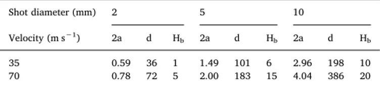
Table 2
Dent diameter (mm), depth (mm) and pile-up height (mm) as a function of shot diameter and velocity.
Shot diameter (mm) 2 5 10
Velocity (m s−1) 2a d Hb 2a d Hb 2a d Hb
35 0.59 36 1 1.49 101 6 2.96 198 10 70 0.78 72 5 2.00 183 15 4.04 386 20
Fig. 3. Evolution of the characteristic dimensionless parameters of the dent as a function of the shot velocity and comparison with the analytical model ofJohnson (1985).
distance of about 20–25 mm from the dent centre. So increasing shot velocity affects mainly the tangential stress, by increasing maximum compressive value; it influences also and the affected zone magnitude: initial stresses are modified on a higher distance from the impact with higher velocity. However, direct comparisons are not trivial as both dents do not have the same geometry.
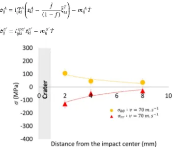
The same analysis has been performed on the sample peened with a 2 mm diameter shot. At a velocity of 35 m s−1, the affected zone was too small to allow obtaining a profile. The stress evolution obtained with a velocity of 70 m s−1is presentedFig. 6. Due to the small size of the dent, it was difficult to obtain measurement close to the edge of the impact. Nevertheless, the same trend is observed as with the 10 mm diameter shot: the absolute stress values decreases with increasing the distance from the dent center. But the maxima are smaller: at 2 mm from the dent, the tangential stress is about 100 MPa and the radial one is about −130 MPa. Moreover, stresses are almost null for distance higher than about 6 mm, which is lower than the ones observed with the biggest shot.
3. Material modelling andfinite element simulations
A semi-physical numerical model, coupling the mechanical and thermodynamical behaviours, was developed at the scale of the phases following the work of Kubler et al. (2011). It consists in a thermo-elastoplastic model with phase transformation. A Representative Vo-lume Element (RVE) of a set of two phases was selected in order to model the behaviour of the austenite/martensite material. The fol-lowing two phases are considered in this study:
- The austenite A of volume fraction(1− f),
- The martensiteα′ which forms from the austenite transformation under thermomechanical loadings, of volume fraction f.
a) Mechanical behaviour law
The macroscopic strain rate of the RVE is given by:
= − + + ′+ ′ +
Ėij (1 f)( ˙εijepA ε˙ijthA) f ε( ˙ijepα ε˙ijthα) ε˙ijT (4)
whereε˙epand ε˙thare respectively the elastoplastic strain rate tensor and
the thermal strain rate tensor of each phase of the RVE.ε˙Tis a mean
phase transformation strain rate tensor. It is defined by: =
ε˙ijT f˙ ξij T
(5) where ξT describes the Mean Instantaneous Transformation Strain (MITS), introduced by Kubler et al. (2011), representing the global contribution of the transformation strain of each individual variant of martensite. It takes into consideration the Bain strain and a part of the Greenwood-Johnson effect by the accommodation mechanisms of Bain in the martensite (appr. 17% compression and 12% expansion for conversion into BCC).
By coupling Eqs.(4)and(5), the following expression of the RVE macroscopic strain rate can be obtained:
⎜ ⎟ = − ⎛ ⎝ + + − ⎞ ⎠ + ′+ ′ Ė f ε ε f f f ε ε (1 ) ˙ ˙ ˙ 1 ξ ( ˙ ˙ ) ij ij epA ijthA ij T ij epα ij thα (6) The localization method ofBerveiller and Zaoui (1979)was used in order to calculate the strain rate tensor of each phaseε˙Aandε˙α′
. That knowledge allows calculating the elastoplastic strain rate of each phase. The stress rate in each phase is given as a function of the tangent elastoplastic modulus tensor lep and the thermal modulus tensor m according to the Eqs.(7)and(8).
⎜ ⎟ = ⎛ ⎝ − − ⎞ ⎠ − σ l ε f f m T ˙ ˙ ˙ (1 )ξ ˙ ijA ijkl epA klA kl T ijA (7) = − ′ ′ ′ ′ σ˙ l ε˙ m T˙ ij α ijkl epα kl α ij α (8)
Fig. 4. Top view of the peened sample and definition of stress directions.
Fig. 5. Evolution of the austenitic residual stress as a function of the distance from the impact center, at the surface of the sample, for a 10 mm diameter shot and for two ve-locities.
Fig. 6. Evolution of the austenitic residual stress as a function of the distance from the impact center, at the surface of the sample, for a 2 mm diameter shot and for a velocity of 70 m s−1.
wheremij=lijklepαklthwithαththe thermal expansion coefficient tensor of
the considered phase.
The macroscopic stress rate of RVE is obtained by:
= − + ′+ ′−
Σ˙ij (1 f σ) ˙ijA fσ˙ijα (σijα σijA) ˙f (9)
The elastoplastic modulusleptensor in each constituent is obtained using the standard Von Mises criterion with the associated plasticflow rule. The martensitic transformation kinetics derives from a thermo-dynamic approach.
Von Mises criterion gives the yield function F for each phase as:
= − − = − − − −
F σ σ R 3 S X S X σ R
2( )( )
eq 0 ij ij ij ij 0
(10) whereσeq, σ0, R andX are respectively the equivalent stress of Von
Mises, the initial yield stress, the isotropic hardening parameter and the kinematical hardening tensor of the considered phase.
Isotropic and kinematic hardenings laws are respectively given by Voce (1955)andArmstrong and Frederick (1966)equations such as:
=
(
− −)
R Q 1 e bε 0 eq p (11) = − X˙ 2C ε γX p 3 * ˙ ˙ ij ijp ij (12)The coefficients Q0, b, C* andγ are material constants associated to
each constituent of the RVE.εeqpis the equivalent plastic strain according
to Von Mises,εpis the plastic strain tensor andp˙ defines the cumulated
plastic strain rate. From Eqs. ((10)–(12)), the elastoplastic modulus is calculated by: = ⎛ ⎝ ⎜ ⎜ − − − + + − − ⎞ ⎠ ⎟ ⎟
(
)
l C I S X σ μ S X σ μ C H γ S X X 3 2 ( ) 3 ( ) 3 * ( ) ijkl ep ijmn mnkl mn mn eq kl kl eq 2σ3 pq pq pq eq (13) where C is the elastic stiffness tensor, μ the shear coefficient and= −
H Q be bε
0 eq
p
.S is the deviatoric stress tensor and I is the fourth order identity tensor. The methodology is fully detailed in appendix A.
b) Martensitic transformation criterion and kinetics
The elastoplastic behaviour of each phase is coupled to a thermo-dynamical model which allows taking into consideration the transfor-mation of austenite into martensite under thermomechanical loadings. In the case of the thermodynamics of irreversible processes and for a transformation independent from time, the driving force Ff of the
martensitic transformation is compared to a critical force Fcas proposed
by Cherkaoui et al. (1998), Kubler et al. (2011) and Patoor and Berveiller (1997).
The driving force for martensitic transformation Ffis defined as a
function of the stress in the austenitic phase, the mean instantaneous transformation strain proposed byKubler et al. (2011)and the tem-perature T, according to the following expression with B a material constant and T0the temperature of the thermodynamical equilibrium:
= − −
Ff σijAξij B T( T)
T
0 (14)
The critical force Fctakes into consideration the influence of the
martensite already formed and the austenite plastic strain. It is defined by:
= − − − − − − −
Fc Fc0 B M( s T0) β[1 exp( αεeqpA)]n κ ln(1 f) (15) where Fc0is the critical force during a cooling without applied stress, Ms
is the temperature at which the martensitic transformation starts during a cooling without stress and f is the martensite volume fraction.β, α, n
andκ are material constants controlling the martensitic transformation kinetics.
For a rate independent transformation, the transformation kinetics derives from the consistency rule such as:
⎧ ⎨ ⎪ ⎩ ⎪ < = = < = = = > F F so f F F and dF dF so f F F and dF dF so f ˙ 0 ˙ 0 ˙ 0 f c f c f c f c f c (16)
The expression of the kinetics of the martensitic transformation coupling the Koistinen and Marburger (1959)andOlson and Cohen (1975)laws in austenite is obtained:
= − ⎧ ⎨ ⎩ − + − − − ⎫ ⎬ ⎭ − df f dσ BdT αβn αε αε dε 1 κ ijξ . exp( ). [1 exp( )] . A ij T eqpA eqpA n eqpA 1 (17) In this expression,σAstands for the stress state tensor in the
aus-tenite phase and εeqpA denotes the equivalent plastic strain within the
austenite. The MITS is expressed according Kubler’s model (Kubler et al., 2011) for isotropic materials considering that it depends only of the stress state within the untransformed austenite:
= + + ⎛ ⎝ − ⎞ ⎠ V V δ d S d S S δ S S ξ 1 3 Δ 9 16[ ] 27 16 ij T ij ijγ kl γ kl γ ij ki γ kj γ 1 2 (18) where V V Δ
is the volume change associated with the martensitic trans-formation,SAis the deviatoric stress tensor within the austenite and d
1
and d2are material constants.
c) Identification of the constitutive law parameters
The different parameters of the model were identified from tensile tests in quasi-static regime (5.10−4s−1) on AISI301LN. The con-stitutive behaviour law was implemented in a user subroutine in Abaqus Explicit. Simulations were carried out on a single cubic element with reduced integration. The identified parameters are presented in Tables 3 and 4 respectively for the plastic behaviour and for the transformation kinetics. The yield stresses of each phase are close to the ones experimentally determined byJacques et al. (2006), using local in-situ determination of the stress vs strain curve in each constituent. Hardening parameters, the parameters of the Olson-Cohen law (κ, n, α) andβ and the coefficients d1and d2of the MITS were identified after a
parametric analysis. The choice of the critical thermodynamical force FC0has an influence on the onset of martensitic transformation.
Fig. 7(a) presents the comparison between the experimental and the simulated behaviour curves which are in good agreement. The mar-tensitic transformation starts at a strain of about 12%, leading to an extra-hardening of the material: as martensite is harder than austenite, the hardness increases with increasing its volume fraction. At the constituent scale (Fig. 7(b)), as expected, martensite exhibits a higher stress state than austenite: it starts from 700 MPa for a strain of 3% and increases up to 1000 MPa for a strain of 30%. Those values are in good agreement with the experimental ones ofBerrahmoune et al. (2004) determined on a AISI 301LN cold-rolled and annealed steel: 990 ± 20 MPa for a strain of 30%. Therefore a good prediction of the mechanical behaviour is observed at both macroscopic and microscopic scales.
d) Single shot-peening simulations
Simulations by Abaqus Explicit were performed with shot peening
Table 3
Elastoplastic main parameters of the numerical model.
σ0(MPa) Q0(MPa) b C*(MPa) γ
Austenite A 320 300 5 750 5 Martensite a’ 850 300 20 0 0
conditions similar to the experimental ones. As the shot is spherical and is projected normal to the surface, a 2D-axisymmetric model has been used. It consists in the impact of a spherical media on a semi-infinite body, which is sufficiently large to overcome the boundaries effects. All the lateral faces of the impacted workpiece are constrained in
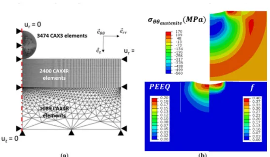
displacement along their normal directions. The mesh is made of quadrilateral elements with reduced integration CAX4R in the upper part, and of triangular elements CAX3 in the bottom part. The shot is meshed with CAX4R elements (seeFig. 8). The CAX4R elements on the body have a size of 10 mm in the impacted zone in order to refine the description in the zone of interest.
The size of the body depends on the diameter and the shot velocity. The bigger the diameter and velocity are, the larger the size of the medium has to be in order to fulfil the semi-infinite condition. An ex-ample is given for peening with a 10 mm diameter shot at 35 m s−1(see Fig. 8). The workpiece is 25 mm deep and 35 mm wide. The shot is meshed with 1089 CAX4R elements; for the workpiece, thefirst 10 millimeters are meshed with 2401 CAX4R elements, the last 20 milli-meters with 1074 CAX3 elements. The contact modelling was defined frictionless.
The mesh size was chosen to ensure acceptable computational time with regards to a convergence of the residual stress profiles. The shot behaviour is assumed to be elastic.
4. Results and discussion
The example of a workpiece impacted by a 10 mm diameter shot at 35 m s−1is presentedFig. 8.
Simulations were carried out and compared to the experiments for microgeometry (Table 5) and residual stresses (Fig. 9).
Simulated values do notfit well the experimental ones for a given velocity. But the effect of velocity increase is well reproduced: in-creasing the speed by a factor 2 increases also the pile-up height by a factor 2 for experiments and simulation. A better prediction could be probably achieved in a future model taking into account strain rate effect.
The stresses in two directions were analysed along the surface, from the dent to the edge of the body:σθθalong eθθandσrralong err. The
martensite volume fraction was also extracted from the simulations: martensite is created within a distance of 2.1 mm from the impact center for a shot velocity of 35 m s−1, and 2.8 mm for 70 m s−1. These values are of the same magnitude as the experimental ones, confirming that martensite appears only in the dent. A good correlation is also observed for residual stress values in both peening conditions. The si-mulations showed that the austenite is in compression in both direc-tions and maximum at the centre of the body:−370 MPa at 35 m s−1 and−780 MPa at 70 m s−1. An increase by around a factor two of the maximum stress is observed when the shot velocity is increased by a factor two. In the tangential direction (σθθ), the stress comes from a
Table 4
Martensitic transformation main parameters of the numerical model. (%)
V V
Δ d1(MPa−1) d2(MPa−1) Fc0(MPa) κ n α β
2 2.10−7 0 −350 585 16 12 1000
Fig. 7. (a) Evolution of experimental and simulated macroscopic stress and martensite volume fraction, (b) Evolution of simulated stress in each phase.
Fig. 8. 2D-axisymmetric model of single shot-pe-ening simulation: (a) mesh and boundaries condi-tions, (b) examples of the distribution of stress in the austenitic phase (σθθ), the equivalent plastic de-formation (PEEQ) and the martensitic volume frac-tion (f).
compression state at the center of the impact to a tensile state at the edge of the dent. Outside the dent, a re-balancing of stress was observed in both directions.
Kobayashi et al. (1998) have performed dynamic impact test by
dropping steel shots of two different sizes (50 and 75 mm) from a height of 2 m on steel plates of width of 50 and 75 mm, respectively. The corresponding shot velocity was estimated at 6.5 m s−1. Due to the large size of the dent, they were able to perform stress measurement inside the dent, in the radial direction. Unexpectedly, they observed that tensile stress was created whereas compressive stresses are ob-tained outside the dent over a range of three to four times the radius of the indentation. Our results are in agreement with Kobayashi’s work outside the dent, even for the magnitude of the affected zone. But a difference is noted in the dent: in their experiment, the workpiece thickness is equal to the shot diameter. In our simulation, plasticity is observed down to 15 mm depth for a shot diameter of 10 mm and the residual stressfield is over the 35 mm depth. The lower ratio of the shot diameter over the workpiece depth could be responsible for a different stressfield. This effect can be highlighted by the numerical results of Shivpuri et al. (2009). They simulated the impact of one single shot on a workpiece of 1.3 mm thickness. When the shot diameter varies from 0.7 to 1.3 mm, the residual stress inside the dent varies approximately from −400 MPa to +150 MPa at the surface. Comparing their simulation with experimental results of Kobayashi et al., they obtained a good agreement outside the dent but the model under estimates stress inside the dent. Following the authors, this is due to the strain-rate effect that
is not taken into account in their model: it uses a rate-independent constitutive law.
To isolate the influence of martensitic transformation on the re-sulting microstructure and stress state, the same numerical simulations were realized considering now the austenite as a stable phase, so the martensitic transformation can no longer occurs. Results such obtained are compared to the previous simulations. The results are presented for a 10 mm diameter shot with a velocity of 70 m s−1. The phase stresses have been analyzed (Fig. 10). The austenite is more in compression when the martensitic transformation is activated, the difference is about 50 MPa. Martensite is in tension in a layer of 1 mm depth from the surface, then in compression down to 2 mm depth. At larger depth, martensite stress state up to tension is observed for larger depth and associated. After this depth, martensite was found in tension, until 600 MPa at 3 mm depth. At this depth there is very few martensite (no more than 1%).
The evolution of the macroscopic stress was calculated using a mixture law (seeFig. 11). When the martensitic transformation is ac-tivated, the macroscopic stress is of−80 MPa at the surface and in-crease until a maximum compression stress of−280 MPa at 2.5 mm depth. When the martensitic transformation is not activated, the max-imum compression stress is obtained at the surface and is slightly higher (−300 MPa). At the opposite, the area which is in compression is smaller when the transformation is switched off: 6 mm against 7 mm when it is activated.
This result confirms the theory ofWohlfahrt (1984)for the case of shot-peening. Without martensitic transformation, the material is fully austenitic and its hardness is smaller than the one of the shot. So the “hammering” effect is dominant: the main part of the energy provided by the shot is consumed in the plastic stretching of the subsurface of the material: the shear and stresses are then maximum at the subsurface. But when the martensitic transformation is activated, a hardening of
Table 5
Comparison of experimental and simulated pile-up height (mm) for two shot velocities. Experimental Simulated
35 m s−1 10 35
70 m s−1 20 60
Fig. 9. Comparison of experimental and simulation stress profile in the austenite for a 10 mm diameter media at: (a) 35 m s−1, (b) 70 m s−1.
Fig. 10. Evolution of intra-phase stress with or without martensitic transformation and of martensite volume fraction in depth, under the impact.
Fig. 11. Evolution of macroscopic stress and martensite volume fraction as a function of depth, with or without martensitic transformation, under the dent.
the material is observed, especially between 0 and 2 mm depth. The energy provided by the shot is no more essentially used in plastic stretching of subsurface but in the one of deeper layers. So the max-imum stress is shifted towards deeper layers, at 3 mm in this case. 5. Conclusions
In this paper, experimental analyses and two-dimensional axisym-metricfinite element simulations were carried out to study the influ-ence of stress-induced martensitic transformation on the residual stress field obtained in a peened metastable austenitic stainless steel. The results of our work reveal the following:
•
The microgeometry analysis of single shot impacts shows char-acteristic parameters of the dent like impact depth and radius close to those predicted, using the analytical model of Johnson whereas this analytical model was developed for elastic-perfectly plasticmaterials.
•
The stress affected area increases when the velocity of the impacting medium is increased.•
The numerical model gives results close to the experiments for both austenitic stress and martensitic volume fraction.The model will be used to model conventional shot peening process on TRIP steels which exhibit more complex microstructures: the ad-vantage of the model is to take into account phase interaction on the resulting stress state.
Acknowledgement
This work was supported by the French Technological Research Institute for Materials, Metallurgy and Processes (IRT M2P) under the CONDOR project.
Appendix A. Definition of the tangent elastoplastic modulus tensorlijmnep for isotropic and kinematical non linear hardenings
The Von-Misès yield function F is defined by:
= − −
F σeq σy R (A.1)
With the equivalent stress
= − −
σ 3 S X S X
2( )( )
eq ij ij ij ij
(A.2) The Voce isotropic hardening
= − −
R Q (10 e bεeq)
p
(A.3) The Armstrong Frederik kinematical hardening formulated in the incremental form:
= −
dX 2Cdε γX dp
3
ij ijp ij
(A.4) Applying the normality rule to the yield function F, the plastic strain rate is obtained
= ∂ ∂ dε d F σ λ ijp ij (A.5) with: ∂ ∂ = − F σ S X σ 3 2 ( ) ij ij ij eq (A.6)
And the plastic multiplier defined by:
= = dλ dε 2 3dε dε eq p ij p ij p (A.7) The plastic multiplier dλ is obtained using the consistency equation dF = 0:
dF = dσeq− dR = 0 (A.8) = − − − − = dF S X dS dX σ Q be dε 3 2 ( )( ) 0 ij ij ij ij eq bε eqp 0 eq p (A.9) With the notationH=Q be−bε ,
0 eq p (A.9) becomes: = − − − = dF S X dS dX σ Hdε 3 2 ( )( ) 0 ij ij ij ij eq eq p (A.10) With: = − dS dσ 1dσ δ 3 ij ij kk ij (A.11) wheredσij=Cijkldεkle =Cijkl(dεkl−dεkl)
p
Using Eqs.(A.5)–(A.6)with(A.11), we obtain:
⎜ ⎟ ⎜ ⎟ = ⎛ ⎝ − − ⎞ ⎠ − ⎛ ⎝ ⎜ ⎛ ⎝ − − ⎞ ⎠ ⎞ ⎠ ⎟ = + dS C dε d S X σ Tr C dε d S X σ δ A Bδ λ3 2 ( ) 1 3 λ 3 2 ( ) ij ijkl kl kl kl eq ijkl kl kl kl eq ij ij ij (A.12)
Thus the expression is simplified such as:
− = − + = −
S X dS S X A Bδ S X A
( ij ij) ij ( ij ij)( ij ij) ( ij ij) ij (A.13)
The rate of the yield function dF becomes:
⎜ ⎟ = − ⎛ ⎝ ⎜ ⎛ ⎝ − − ⎞ ⎠ − ⎞ ⎠ ⎟ − = dF S X σ C dε d S X σ dX Hdε 3 2 ( ) λ3 2 ( ) 0 ij ij eq ijkl kl kl kl eq ij eqp (A.14) In the case of isotropic elasticity where the elastic constants are defined by Cijkl= 2μIijkl+λ*δijδklwhereμ and λ* are Lamé coefficients, the
following simplifications are obtained:
− = − + = − = −
S X C dε S X μI λ δ δ dε S X μI dε μ S X dε
( ij ij) ijkl kl ( ij ij)(2 ijkl *ij kl) kl ( ij ij)2 ijkl kl 2 ( kl kl) kl (A.15)
− − = − + − = − − =
S X C S X S X μI λ δ δ S X μ S X S X μ σ
( ) ( ) ( )(2 * )( ) 2 ( )( ) 2 2
3
ij ij ijkl kl kl ij ij ijkl ij kl kl kl ij ij ij ij eq2 (A.16)
⎜ ⎟ − = − ⎛ ⎝ − ⎞ ⎠= − ⎛ ⎝ − − ⎞ ⎠ = − − S X dX S X Cdε γX dp S X Cdλ S X σ γX dλ Cσ dλ γ S X X dλ ( ) ( ) 2 3 ( ) 2 3 3 2 ( ) 2 3 ( ) ij ij ij ij ij ijp ij ij ij ij ij eq ij eq ij ij ij (A.17) The consistency rules dF = 0 is expressed:
= ⎛ ⎝ − − − + − ⎞ ⎠− = dF σ μ S X dε μσ dλ Cσ dλ γ S X X dλ Hdλ 3 2 2 ( ) 2 2 3 ( ) 0 eq ij ij ij eq eq ij ij ij (A.18) From Eq.(A.18), the plastic multiplier dλ is obtained:
= − + + − − =
(
)
d μ S X dε σ μ C H γ S X X A dε λ 3 ( ) 3 ( ) ij ij ij eq σ ij ij ij ij ij 3 2eq (A.19)The behaviour law defined by the stress rate dσijis obtained:
⎜ ⎟ ⎜ ⎟ = − = ⎛ ⎝ − − ⎞ ⎠ = ⎛ ⎝ − − ⎞ ⎠ dσ C dε dε C dε d S X σ C dε S X σ A dε ( ) λ3 2 ( ) 3 2 ( ) ij ijkl kl kl p ijkl kl kl kl eq ijkl kl kl kl eq mn mn (A.20) Sinceσij=lijmndε ep
mn, the elastoplastic modulus for a behaviour with non-linear isotropic and kinematical hardenings is given by:
⎜ ⎟ = ⎛ ⎝ − − ⎞ ⎠ l C I S X σ A 3 2 ( ) ijmnep ijkl klmn kl kl eq mn (A.21) References
Armstrong, P.J., Frederick, C.O., 1966. A Mathematical Representation of the Multiaxial Bauschinger Effect. Central electricity generation board and Berkeley nuclear la-boratories, Research & Development department.
Berrahmoune, M.R., Berveiller, S., Inal, K., Moulin, A., Patoor, E., 2004. Analysis of the martensitic transformation at various scales in TRIP steels. Mater. Sci. Eng. A 378, 304–307.
Berveiller, M., Zaoui, A., 1979. An extension of the self-consistent scheme to plastically flowing polycrystals. J. Mech. Phys. Solids 26, 325–344.
Chaise, T., Nelias, D., Sadeghi, F., 2011. On the effect of isotropic hardening on the coefficient of restitution for single repeated impacts using a semi-analytical method. Tribol. Trans. 54 (5), 714–722.
Chaise, T., Li, J., Nélias, D., Kubler, R., Taheri, S., Douchet, G., Robin, V., Gilles, P., 2012. Modelling of multiple impacts for the prediction of distortions and residual stresses induced by ultrasonic shot peening (USP). J. Mater. Process. Technol. 212 (10), 2080–2090.
Chaise, T., 2011. Modélisation mécanique par méthode semi analytique: du contact roulant élastoplastique aux impacts multiples. PhD Thesis. INSA de Lyon.
Cherkaoui, M., Berveiller, M., Sabar, H., 1998. Micromechanical modeling of martensitic transformation induced plasticity (TRIP) in austenitic single crystals. Int. J. Plast. 14, 597–626.
Cherkaoui, M., Berveiller, M., Lemoine, X., 2000. Coupling between plasticity and mar-tensitic phase transformation: overall behavior of polycrystalline TRIP steels. Int. J. Plast. 16, 1215–1241.
Diani, J.M., Sabar, H., Berveiller, M., 1995. Micromechanical modelling of the transfor-mation induced plasticity (TRIP) phenomenon in steels. Int. J. Eng. Sci. 33 (13), 1921–1934.
Edberg, J., Lindgren, L., Mori, K., 1995. Shot peening simulated by two different finite element formulations. In: Shen, Dawson (Eds.), Proc. Int. Conf. Numerical Methods in Industrial Forming Processes 5. Ithaca, New York USA. pp. 425–430.
Fargas, G., Roa, J.J., Mateo, A., 2015. Effect of shot peening on metastable austenitic stainless steels. Mater. Sci. Eng. A 641, 290–296.
Fathallah, R., Inglebert, G., Castex, L., 2003. Determination of shot peening coefficient of restitution. Surf. Eng. 19, 109–113.
Fischer F.D., Modelling and Simulation of Transformation Induced Plasticity in Elasto-Plastic Materials, in Mechanics of Solids with Phase Changes, 1997, Volume 368 of
the series International Centre for Mechanical Sciences pp 189-237
Fischlschweiger, M., Cailletaud, G., Antretter, T., 2012. A mean-field model for trans-formation induced plasticity including backstress effects for non-proportional load-ings. Int. J. Plast. 37, 53–71.
Frija, M., Hassine, T., Fathallah, R., Bouraoui, C., Dogui, A., 2006. Finite element mod-elling of shot peening process: prediction of the compressive residual stresses, the plastic deformations and the surface integrity. Mater. Sci. Eng. A 426 (1–2), 173–180.
Fu, P., Zhan, K., Jiang, C., 2013. Micro-structure and surface layer properties of 18CrNiMo7-6 steel after multistep shot peening. Mater. Des. 51, 309–314.
Gallée, S., Pilvin, P., 2010. Deep drawing simulation of a metastable austenitic stainless steel using a two-phase model. J. Mater. Process. Technol. 210, 835–843.
Gallée, S., Manach, P.Y., Thuillier, S., 2007. Mechanical behavior of a metastable aus-tenitic stainless steel under simple and complex loading paths. Mater. Sci. Eng. A 466, 47–55.
Gallitelli, D., Boyer, V., Gelineau, M., Colaitis, Y., Rouhaud, E., Retraint, D., Kubler, R., Desvignes, M., Barralier, L., 2016. Simulation of shot peening: from process para-meters to residual stressfields in a structure. C. R. Mec. 334, 355–374.
Guagliano, M., 2001. Relating Almen intensity to residual stresses induced by shot pe-ening: a numerical approach. J. Mater. Process. Technol. 110 (3), 277–286.
Halilovic, M., Issa, S., Wallin, M., Hallberg, H., Ristinmaa, M., 2016. Prediction of the residual state in 304 austenite steel after laser shock peening– effects of plastic de-formation and martensitic phase transde-formation. Int. J. Mech. Sci. 111–112, 24–34.
Hecker, S.S., Stout, M.G., Staudhammer, K.P., Smith, J.L., 1982. Effect of strain state and strain rate on deformation-induced transformation in 304 stainless steel: part I. Magnetic measurements and mechanical behavior. Metall. Trans. A 13 (4), 619–626.
Hong, T., Ooi, J.Y., Shaw, B., 2008. A numerical simulation to relate the shot peening parameters to the induced residual stresses. Eng. Fail. Anal. 15 (8), 1097–1110.
Iwamoto, T., Tsuta, T., Tomita, Y., 1998. Investigation on deformation mode dependence of strain-induced martensitic transformation in trip steels and modelling of trans-formation kinetics. Int. J. Mech. Sci. 40 (2–3), 173–182.
Jacques, P.J., Furnémont, Q., Godet, S., Pardoen, T., Conlon, K., Delannay, F., 2006. Micromachanical characterization of TRIP-assisted multiphase steels by in situ neu-tron diffraction. Philos. Mag. 86 (16), 2377–2398.
Jebahi, M., Gakwaya, A., Levesque, L., Mechri, O., Ba, K., 2016. Robust methodology to simulate real shot peening process using discrete-continuum coupling method. Int. J. Mech. Sci. 107, 21–33.
Kleber, X., Barroso, S.P., 2010. Investigation of shot-peened austenitic stainless steel 304L by means of magnetic Barkhausen noise. Mater. Sci. Eng. A 527 (21–22), 6046–6052.
Kobayashi, M., Matsui, T., Murakami, Y., 1998. Mechanism of creation of compressive residual stress by shot peening. Int. J. Fatigue 20 (5), 351–357.
Koistinen, D.P., Marburger, R.E., 1959. A general prescribing the extent of the austenite-martensite transformation in pure iron-carbon alloys and plain carbon steels. Acta Metall. 7 (1), 59–60.
Kubler, R.F., Berveiller, M., Buessler, P., 2011. Semi phenomenological modelling of the behavior of TRIP steels. Int. J. Plast. 27, 299–327.
Lebedev, A.A., Kosarchuk, V.V., 2000. Influence of phase transformation on the me-chanical properties of austenitic stainless steels. Int. J. Plast. 16, 749–767.
Leblond, J.B., Devaux, J., Devaux, J.C., 1989. Mathematical modelling of transformation plasticity in steels I: case of ideal-plastic phases. Int. J. Plast. 5, 551–572.
Leblond, J.B., 1989. Mathematical modelling of transformation plasticity in steels II: coupling with strain hardening phenomena. Int. J. Plast. 5, 573–591.
Levitas, V.I., 1998. Thermomechanical theory of martensitic phase transformation in elastic materials. Int. J. Solids Struct. 35 (9–10), 889–940.
Lillamand, I., Barrallier, L., Lalanne, B., Castex, L., 2001. Cyclic modelling of the me-chanical state produced by shot-peening. Fatigue Fract. Eng. Mater. Struct. 24, 93–104.
Lindgren, L.-E., Olsson, M., Carlsson, P., 2010. Simulation of hydroforming of steel tube made of metastable stainless steel. Int. J. Plast. 26, 1576–1590.
Mahmoudi, A.H., Ghasemi, A., Farrahi, G.H., Sherafatnia, K., 2016. A comprehensive experimental and numerical study on redistribution of residual stresses by shot pe-ening. Mater. Des. 90, 478–487.
Majzoobi, G.H., Azizi, R., Alavi Nia, A., 2005. A three-dimensional simulation of shot peening process using multiple shot impacts. J. Mater. Process. Technol. 164–165, 1226–1234.
Mann, P., Miao, H.Y., Gariepy, A., Levesque, M., Chromik, R.R., 2015. Residual stress near single shot peening impingements determined by nanoindentation and numerical simulations. J. Mater. Sci. 50, 2284–2297.
Meguid, S.A., Shagal, G., Stranart, J.C., Daly, J., 1999. Three-dimensional dynamicfinite element analysis of peening induced residual stresses. Finite Elem. Anal. Des. 31, 179–191.
Meguid, S.A., Shagal, G., Stranart, J.C., 2002. 3D FE analysis of peening of strain-rate sensitive materials using multiple impingement model. Int. J. Impact Eng. 27 (2), 119–134.
Miao, H.Y., Larose, S., Perron, C., Levesque, M., 2009. On the potential application of a 3D randomfinite element model for the simulation of shot peening. Adv. Eng. Softw. 40, 1023–1038.
Mori, K., Osakada, K., Matsuoka, N., 1994. Finite element analysis of peening process with plasticity deforming shot. J. Mater. Process. Technol. 45 (1–4), 607–612.
Msolli, S., Martiny, M., Costa Cadoso, M., Pessanha Moreira, L., Mercier, S., Molinari, A., 2016. Numerical modeling of the deformation of AISI 304L using a tangent additive Mori-tanaka homogenization scheme: application to sheet metal forming. J. Mater. Process. Technol. 235, 187–205.
Murugaratnam, K., Utili, S., Petrinic, N., 2015. A combined DEM-FEM numerical method for Shot Peening parameter optimization. Adv. Eng. Softw. 79, 13–26.
Musinski, W.D., McDowell, D.L., 2015. On the eigenstrain application of shot-peened residual stresses within a crystal plasticity framework: application to Ni-base super-alloy specimens. Int. J. Mech. Sci. 100, 195–208.
Nguyen, V.B., Poh, H.J., Zhang, Y.-W., 2014. Predicting shot peening coverage using multiphase computationalfluid dynamics simulations. Powder Technol. 256, 100–112.
Olson, G.B., Cohen, M., 1975. Kinetics of strain-induced martensitic nucleation. Metall. Trans. A 6 (4), 791–795.
Olson, G.B., Cohen, M., 1982. Stress-assisted isothermal martensitic transformation: ap-plication to TRIP steels. Metall. Trans. A 13, 1907–1914.
Patoor, E., Berveiller, M., 1997. Micromechanical Modeling of the Thermomechanical Behavior of Shape Memory Alloys. Mechanics of Solids with Phase Changes. Springerpp. 121–188.
Perdahcioglu, E.S., Geijselaers, H.J.M., Huetink, J., 2008. Influence of stress state and strain path on deformation induced martensitic transformations. Mater. Sci. Eng. A 481–482, 727–731.
Rouhaud, E., Deslaef, D., Lu, J., Chaboche, J.L., 2005. Modeling of residual stress, shot peening. In: Lu, Jian (Ed.), Handbook on Residual Stress, Society of Experimental Mechanics.
Rouquette, S., Rouhaud, E., François, M., Roos, A., Chaboche, J.-L., 2009. Coupled thermo-mechanical simulations of shot impacts: effects of the temperature on the residual stressfield due to shot-peening. J. Mater. Process. Technol. 209 (8), 3879–3886.
Schiffner, K., Droste gen. Helling, C., 1999. Simulation of residual stresses by shot pe-ening. Comput. Struct. 72 (1–3), 329–340.
Sherafatnia, K., Farrahi, G.H., Mahmoudi, A.H., Ghasemi, A., 2016. Experimental and analytical determination of shot peening residual stresses considering friction and real unloading behavior. Mater. Sci. Eng. A 657, 309–321.
Shivpuri, R., Cheng, X., Mao, Y., 2009. Elasto-plastic pseudo-dynamic numerical model for the design of shot peening process parameters. Mater. Des. 30, 3112–3120.
Stringfellow, R.G., Parks, D., Olson, G.B., 1992. A constitutive model for transformation plasticity accompanying strain-induced martensitic transformation in metastable austenitic steels. Acta Metall. Mater. 40 (7), 1703–1716.
Talonen, J., Hanninen, H., 2007. Formation of shear bands and strain-induced martensite during plastic deformation of metastable austenitic stainless steels. Acta Mater. 55, 6108–6118.
Tomita, Y., Iwamoto, T., 1995. Constitutive modeling of TRIP steel and its application to the improvement of mechanical properties. Int. J. Mech. Sci. 37 (12), 1295–1305.
Turski, M., Clitheroe, S., Evans, A.D., Rodopoulos, C., 2010. Engineering the residual stress state and microstructure of stainless steel with mechanical surface treatments. Appl. Phys. A 99 (3), 549–556.
Voce, E., 1955. A practical strain-hardening function. Metallurgia 51 (307), 219–226.
Wohlfahrt, H., 1984. The influence of peening conditions on the resulting distribution of residual stress. In: Proceedings of the Second International Conference on Shot Peening. Springer. pp. 316–331.
Yang, F., Chen, Z., Meguid, S.A., 2015. Effect of initial surface finish on effectivness of shot peening treatment using enhanced periodic cell model. Int. J. Mater. Des. 11, 463–478.