Science Arts & Métiers (SAM)
is an open access repository that collects the work of Arts et Métiers Institute of Technology researchers and makes it freely available over the web where possible.
This is an author-deposited version published in: https://sam.ensam.eu Handle ID: .http://hdl.handle.net/10985/11201
To cite this version :
Mohamed TRABELSI, Eric SEMAIL, Ngac Ky NGUYEN, Fabien MEINGUET - Open-Switch and Open-Phase Real Time FDI Process for Multiphase PM Synchronous Motors - In: ISIE'16, Etats-Unis, 2016-06 - Open-Switch and Open-Phase Real Time FDI Process for Multiphase PM Synchronous Motors - 2016
Any correspondence concerning this service should be sent to the repository Administrator : [email protected]
Open-Switch and Open-Phase Real Time FDI Process
for Multiphase PM Synchronous Motors
(1)Mohamed Trabelsi, (1)Eric Semail, (1)Ngac Ky Nguyen, (2)Fabien Meinguet
(1) Univ. Lille, Centrale Lille, Arts et Metiers ParisTech, HEI, EA 2697 - L2EP - Laboratoire d’Electrotechnique et
d’Electronique de Puissance, F-59000 Lille, France
(2)Thales Alenia Space - Thales Group, Charleroi, Belgium
E-mails : (1){mohamed.trabelsi, eric.semail, ngacky.nguyen}@ensam.eu (2) [email protected]
Abstract—This paper deals with the real time Fault Detection
and Identification (FDI) process of inverter Open Switch Fault (OSF) and Open Phase Fault (OPF) in five-phase PMSM designed for aerospace applications in which the electric drive system has particular operating characteristics either in healthy states or in the faulty ones. Two original contributions are considered in this paper. They consist in normalizing the input variables of the FDI process applied to multiphase system and compensating the noise (switching and sensors noises) and dc-component resulting from the fault occurrence. The proposed strategy uses multiple normalized criterias derived from the measured phase currents and the references currents obtained from the outputs of the speed controllers. The FDI shows independence with respect to transient states and to switching and measurement noises. Moreover, it can be easily included in an existing software without any additional sensors. The validity of the proposed method is verified by Matlab/Simulink simulation tests.
Keywords— Aerospace safety, five-phase PMSM, multiphase elctric drive, inverter fault, closed-loop control, fault detection and identification, open-phase.
I. INTRODUCTION
Five-phase Permanent Magnet Synchronous Motor (PMSM) considered in this work is being studied for an aerospace Thrust Vector Control (TVC) system. The TVC system controls the orientation of the nozzle in order to define the trajectory of the rocket, as shown in Fig.1. The proposed solution is composed of two electromechanical five-phase PMSM which replace the classical structure based on two hydraulic actuators. More details about the general functioning principle are given in [1] and [2] but for six-phase PMSM that is more adaptable to high power and presents more degrees of freedoms (DoF) especially under short-circuit fault. The choice of any phase number depends essentially of the fault number that can be tolerated in the system. The studied system in this work uses two five-phase PMSM which are electrically independents. However, the selected structure is considered sufficient for opened switch or phase faults tolerance. Each motor uses a five-leg Voltage Source Inverter (VSI) fed by batteries which replace the hydraulic tank. In TVC system, one of important constraints is that the drive has to continue to operate under fault conditions.
These aerospace systems are exposed to hard aerospace environmental and functional conditions inducing faults essentially related to the VSI. In previously published
Fig.1 : Considered Thrust Vector Control system (TVC). (a) Torque generation for 3 inclination cases of the thrust, (b) Upper view of actuators axis and inclination angle φ.
statistical studies [3], the percentage of faults for three-phase variable-speed drives was evaluated to about 60% due to the experiences of user during the first year of operation. In addition, 70% of these faults were related to power switches of the VSI, such as short-circuit fault and open-circuit fault. The impact of a short-circuit fault is usually destructive with classical star coupled drives and needs either special VSI with two transistors in series or with supplementary components such as triac or special architecture such as open-windings drives [4]. It is the reason why only opened switch or opened phase faults will be considered in this paper without any additional power component in comparison with normal operation.
For classical three-phase systems, reviews of FDI methods have been already given in [5] before 2009 and recently in [6]. They can be classified as model based methods [7], [8] or signal based methods. The first ones need an accurate system model to achieve a robust algorithm. Techniques based on analysis of the signals require the measurement of inverter outputs (currents or voltages). Methods based on voltage analysis, addressed in [9]-[12], have a major drawback because an extra hardware or extra sensors are usually needed for real time implementation. Techniques based on currents have been reported in [13]-[17] with extension, in [18]-[20], to multiple-fault occurrence. However, these techniques have been developed for conventional systems with balanced three-phase currents and sinusoidal back-EMFs of PMSM drives and cannot be applied directly to multiphase systems for fault diagnostic purposes. In fact, while working with multiphase PMSM drives, usually the back-EMFs contain multiple
harmonic components such as third, fifth, seventh and ninth harmonic. Consequently, the reference and the measured phase currents can be distorted with the same components, when using the Maximum Torque Per Ampere (MTPA) control strategy, resulting thus in false alarms when applying the conventional FDI strategies.
Regarding the multiphase systems, there are only a few works [21], [22] that address specifically the FDI problem for multiphase systems especially under inverter switch faults. In [21], [22], a five-phase Permanent Magnet machine with trapezoidal electromotive force is considered. Injection of third harmonic current, which is one of the specificity of this kind of machine in terms of control, is taken into account and possibility of detection and identification is validated but without consideration on robustness.
In the proposed paper, the FDI algorithm, based on analysis of the currents, considers, as in [21], [22], injection of a third harmonic of current but, as in [18]-[19], introduces a normalization of the currents in order to prevent the generation of false alarms.
In the first paragraph, faults effects in a five-phase machine are presented and analyzed. In the second paragraph, a FDI algorithm with normalization is given including, for a robust identification of the nature of fault, a compensation of fault effect. The last paragraph provides simulation results and test of robustness in case of torque load variations.
II. MULTIPHASE SYSTEM STRUCTURE AND OPERATING
CHARACTERISTICS UNDER INVERTER FAULTS
The early step in this work consists in analyzing the overall electric drive system performances and dynamics under fault conditions. This step aims essentially to design a robust FDI process with respect to the following problematic questions:
Which pertinent variables that will be selected for a robust FDI process design?
Is the designed FDI easy for real time integration in the existing electric drive system with respect to the cost function and the complexity?
Is the designed FDI robust for all operating conditions? In other words, what is the sensivity of the FDI process to the parameters variation, the noises and the transient states?
How fast is the FDI process, permitting a minimum time delay between the fault occurrence and the fault identification?
Moreover, in order to develop low-cost FDI process, it is strongly desirable to avoid the use of extra sensors. So, FDI process based on currents are attractive in comparison with those based on voltages. For this reason, it is chosen in this work that the fault effects analysis will be achieved only regarding the dynamic of the measured phase currents which will be used then as input variables for the proposed FDI process.
A. System structure and VSI topology
This section consists in analyzing the effects of OSF and OPF on the five-phase PMSM. A simplified scheme of the
48 V DC -b us V olt ag e
Fig.2 : Configuration of the electromechanical conversion chain used in the TVC System .
considered electric drive, including the power electronic part, the electric machines and its control, is shown in Fig.2. It is composed of a five-leg VSI, a five-phase vector-controlled PMSM and a variable load generated through three-phase PMSM.
The VSI, composed of five legs (Fig.2), is fed by a constant voltage source provided through a capacitive dc-link. Each leg features two power switches (Tk, Tk+5, k =1, 2, 3, 4,
5) with anti-parallel connected freewheeling diodes ( DK,
DK + 5). The VSI is controlled by the gate switching signals
( SK, SK + 5)∈ {0 ,1 } . The gate signal SK or SK + 5 is equal to
“1” when the switch is conducting and equal to “0” when the switch is open.
The output currents of the VSI, in the original frame, can be expressed in steady states as follows:
( )
2 n 1 5 h i ( t )n I sin h p t h 1 π Ω − ∞ = − = (1)where, n=1,..,5 represents the phase current (ia, ib, ic, id, and ie), h is the order of the current harmonics, Ih is the
magnitude of the hth current harmonic, and pΩ is the electrical fundamental frequency.
For the PMSM under study, only the first and the third harmonics are considered but the algorithm could be extended to non-sinusoidal machines having more harmonics. So, the output currents of the VSI given in (1) can be reduced, for a healthy condition, as follows:
( )
2( )
2 1 3 i ( t )n I sin p t n 1 I sin 3 p t n 1 5 5 π π Ω Ω = − − + − − (2)B. Inverter Fault Effects Analysis
The OSF and OPF effects analysis are achieved using the electric drive structure shown in Fig. 2. The parameters of the five-phase PMSM are given in Table. I. All results are obtained in closed loop control and without system reconfiguration after fault occurrence. However, the pre-fault
control, as well as the post-fault control, are achieved without any change in the control loops (speed and current loops) or in the maximum torque per ampere algorithm (MTPA), as shown in Fig. 2. The reference currents (idq-ref) are provided from the
outer speed loop and the MTPA strategy.
Simulated results on FEA under healthy and faulty conditions are shown in Fig. 3, Fig. 4 and Fig. 5. Three fault modes are investigated: an open switch fault, open phase fault, and OSF or OPF in the case of non-sinusoidal back-EMFs (with 3rd harmonic). During both healthy conditions and faulty modes, the reference speed and the load torque are set to 1000 rpm and 15 Nm, respectively. For both normal operating condition and post-fault operation mode of the electric drive system, the VSI is built from the power switches and OSF or OPF in the case of non-sinusoidal back-EMFs (with 3rd harmonic). During both healthy conditions and faulty modes, the reference speed and the load torque are set to 1000 rpm and 15 Nm, respectively. For both normal operating condition and post-fault operation mode of the electric drive system, the VSI is built from the power switches considering transistors and antiparallel diodes.
Simulation results addressed in Fig. 3 and Fig. 4 present respectively the time domain waveforms of the phase currents (Fig. 3a and Fig. 4a), the spectrogram of the faulty phase a (Fig. 3b and Fig. 4b) and the spectrogram of one healthy phase
b (Fig. 3c and Fig. 4c) for both healthy and faulty conditions.
1) Healthy condition of the VSI: In the first test, the electric drive system operates without any fault. It is observed that the phase currents are sinusoidal. These results are confirmed by the spectrogram of the phase current, showing thus the fundamental component and low amplitude high-frequency noise and switching effects.
2) Single open switch or open phase faults: In the second test (Fig. 3), an open switch fault is considered for the VSI at
t =0.1018 s. In this case, the open circuit fault is applied to the
upper transistor T1 of the first inverter leg (phase a) during permanent operating mode of the electric drive system. It is observed that the dynamic performances of the system are affected only when the current of the faulty inverter leg is nullified (because of the open-circuit fault of T1). During the rest of the period when the current ia(t) becomes negative, the electric drive system performances are similar to the healthy state. Regarding the double OSF of T1 and T6, resulting in an open phase fault case (Fig. 4), its occurrence results in similar effects but over a fundamental current period because two transistors are involved in this case. Although the OSF (T1) or the OPF (T1 and T6), the five-phase PMSM is still capable to operate but with torque and speed ripples, leading to more stress and thermal cycling in the power switches and other functional blocks in the electromechanical conversion chain. It should be noted that the fault occurrence, regardless the fault type (single or multiple) and location, creates an asymmetry in the electric drive system, resulting in a periodic oscillation of the PMSM output torque. All these mechanical new-constraints induce in the motor several harmonic components even in the healthy phases: the currents have not sinusoidal shapes immediately after the fault occurrences
Table. I : FIVE PHASE PMSMPARAMETERS
R (Ω) Lm(H) Ls p P (kW) Imax dc-bus 9.1 mΩ 3.1 mH 0.9 mH 7 10.5 125A 48V 0.08 0.085 0.09 0.095 0.1 0.105 0.11 0.115 0.12 -50 0 50 (a) Time (s) Ph as e curr ent s (A
) ia(A) ib(A) ic(A) id(A) ie(A)
0 1 2 3 4 5 6 7 8 0 5 10 15 20 25 30 35 (b) Harmonic order C urre nt m agn it ud e (A ) 0 1 2 3 4 5 6 7 8 9 0 5 10 15 20 25 30 35 (c) Harmonic order Healthy VSI : h1 = 21.31 A , THD = 0.97% OSF in the VSI : h1 = 29.44 A , THD= 25.74% Healthy VSI
OSF in the VSI
Healthy VSI OSF in the VSI Healthy VSI : h1 = 21.31 A , THD = 0.97%
OSF in the VSI : h1 = 10.62 A , THD = 43.98%
Fig.3: waveforms of the phase currents and their corresponding spectrogram for a healthy VSI and an open switch fault (OSF) of transistor T1. (a) Phase currents waveforms. (b) Spectrogram of the phase current ia (t). (c)
Spectrogram of the phase current ib(t).
0 1 2 3 4 5 6 7 8 9 0 10 20 30 40
(c) Harmonic order (phase b) 0.08 0.085 0.09 0.095 0.1 0.105 0.11 0.115 0.12 -50 0 50 (a) Time (s) P hase cu rr ent s (A ) 0 1 2 3 4 5 6 7 8 0 5 10 15 20 25 30 35
(b) Harmonic order (phase a)
Cu rr en t m ag ni tu de ( A ) Healthy VSI
OPF in the VSI
0 1 2 3 4 5 6 7 8 0
0.05 0.1
Zoom
ia(t) ib(t) ic(t) id(t) ie(t)
OPF in the VSI Healthy VSI
Healthy VSI :
h1 = 21.31 A , THD = 0.97% Healthy VSI : h1 = 21.31 A , THD = 0.97%
Fig.4: Time-domain waveforms of the phase currents and their corresponding spectrogram for a healthy VSI and an open phase fault (OPF). (a) Phase currents waveforms. (b) Spectrogram of the phase current ia (t). (c)
Spectrogram of the phase current ib(t).
because of the effect of mutual inductances between the phases. Each type of inverter fault (OSF or OPF) draws a particular form and modification of the phase currents, with a particular harmonic content. This characteristic is observed
when examining the spectrograms depicted in Fig.3.b-c and Fig.4.b-c. They contain harmonics multiplying by fundamental current frequency in addition to the dc component which is observed in all phase currents under an OSF. Regarding the amplitudes of the observed harmonic components in the other healthy phases (e.g phase b (Fig.3(c)), they are different in comparison with the spectrogram of the faulty phase a. For the healthy phase b, it is observed in the current ib(t) an increase of the fundamental harmonic and the apparition of a third harmonic component.
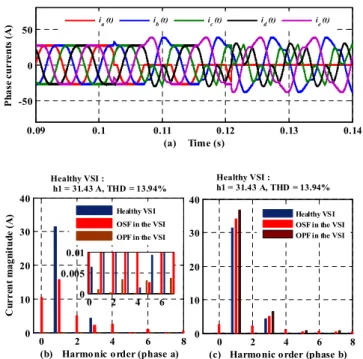
3) 3rd harmonic effect on the five-phase PMSM: Results addressed in Fig.5 are obtained in pre-fault operation and post-fault operation of the electric drive system with a third current harmonic component applied to the five-phase PMSM according to MTPA strategy. As, in the previous tests, the reference speed and the load torque are set to 1000 rpm and 15 Nm, respectively. If in time representation the currents appear as more complex, the spectrum of current contain, in OSF and OPF, the same component harmonic as previously.
III. PROPOSED REAL-TIME FDIPROCESS
The block diagram of the proposed FDI is illustrated in Fig. 6. It consists in five main steps:
1) Step_I : Fault profiles extraction in the decoupled
subspaces d1q1 and d3q3 frames. This step permits to take into account the dynamic of the electric drive system in closed-loop operation. These fault quantities are expressed by
fd1q1( t ) i= d1q1_ ref( t ) i− d1q1_ mes( t ) (3)
fd 3q3( t ) i= d 3q3_ ref( t ) i−d 3q3_ mes( t ) (4)
The fault profiles fdq (t) are positive or negative when an
OSF or OPF occurs in the VSI. They are close to zero under healthy condition. These quantities contain all faulty conditions of the VSI and are achieved for all operating points of the five-phase PMSM.
2) Step_II : Generation of equivalent fault profiles in
original frame abcde. It consists mainly in applying successively the Park-inverse and generalized Concordia-inverse transformations (7) and (8) to the fault profiles obtained in the first step.
The equivalent Concordia fault profiles can be obtained by • For the rotating d1q1-frame :
[
]
1 d 1q1 fαβ P( )θ − f = (5) • For the rotating d3q3-frame :[
]
1xy d 3q3
f P( 3 )θ − f
=
(6)
However, the new fault profiles in original frame are a function of quantities [fαβ-xy (t)] as follow:
fault profiles genration in d1q1 frame fault profiles genration in d3q3 frame 1 id mes iq mes1 id ref1 iq ref1 id mes3 iq mes3 id ref3 iq ref3 Fault profiles normalisation in (abcde) frame Concordia Current modulus Pa rk Tr an sf or m & Co ncordia T ransf or m Fault detection Fault identification Noise and dc component compensation Faulty switches idq_mes ≥ II I III V
Fig. 6. Block diagram of the proposed real time FDI process
[
]
t n xy t xy 0 5 f ( t ) C f ( t ) 2 C αβ αβ = (7) where, [fn (t)] =[ fabcde (t)], 2 4 6 81 cos cos cos cos
5 5 5 5
C
2 4 6 8
0 sin sin sin sin
5 5 5 5 π π π π αβ = π π π π (8) 4 8 12 16
1 cos cos cos cos
5 5 5 5
4 8 12 16
0 sin sin sin sin
5 5 5 5 Cxy π π π π π π π π = (9)
3) Step_III : Measured phase currents and fault profiles
normalization. It is possible to use the input variables of the
0 2 4 6 8 0 10 20 30 40
(b) Harmonic order (phase a)
C urre nt m agn it ud e (A ) 0 2 4 6 8 0 10 20 30 40
(c) Harmonic order (phase b)
0.09 0.1 0.11 0.12 0.13 0.14 -50 0 50 (a) Time (s) P hase curr ent s (A ) 0 2 4 6 0 0.005 0.01 Healthy VSI OSF in the VSI OPF in the VSI
Healthy VSI OSF in the VSI OPF in the VSI
ia (t) ib (t) ic (t) id (t) ie (t)
Healthy VSI :
h1 = 31.43 A, THD = 13.94%
Healthy VSI :
h1 = 31.43 A, THD = 13.94%
Fig.5: Time-domain waveforms of the phase currents and their corresponding spectrogram for a healthy VSI, an OSF and an OPF with non-sinusoidal back-EMFs of the PMSM. (a) Phase currents waveforms. (b) Spectrogram of the
FDI process (fault profiles fn(t) and the measured phase
currents in(t)) without any conditioning. Unfortunately, the
reliability is then very low under mechanical operating conditions change, as speed and load changes. A way to overcome this problem consists in normalizing these quantities. In fact, since these variables are the phase currents or derived from the phase currents, they can be normalized according to the sum of Concordia current modulus for each decoupled subspace as follows:
2 2 2 2 is i ixy i i ix iy 9 5 Ih1 Ih3 2 5 α αβ β = + = + + + = + (10)
Here, it is clear that the current modulus is depends on the first and third harmonic components. For copper-losses optimization purposes in PMSM, the current vector is generally co-linear with the EMFs vector (Maximum Torque Per Ampere (MTPA) strategy [23]). As a result, the ratio of the third current harmonic and the first one is the same as the ratio of the third back-EMF harmonic and the first one. As a consequence, it is thus quite easy to express the third harmonic component Ih3 as a fractional ratio of the first harmonic Ih1 as
follow:
h3 h1
I =ρ.I (11)
Hence, the total current modulus (10) can be simply reduced to:
( )
9 9 1 5 h1 5 h3 is I 1 I 5 5 2 ρ 2 ρ = + = + (12)It is clear that the current modulus is is a constant and depends only of the peak value of the first harmonic or the third harmonic, and the ratioρ . These parameters can be easily experimentally fixed by measuring the back-EMFs of the PMSM.
Finally, the normalized input variables of the FDI process are obtained: ia,b,c,d ,e inN( t ) i ixy fa,b,c,d ,e fnN( t ) i ixy αβ αβ = + = + (13) where, 2 5 2 2 inN( t ) sin p t ( n 1 ) sin 3( p t ( n 1 ) ) 5 5 9 5 5 π π Ω ρ Ω ρ = − − + − − +
Here, it should be noted that the fault profiles is normalized in the same way as the phase current since they are derived from them.
One of the important features is to work with normalized input variables of the diagnostic process, allowing the FDI
strategy to be more independent of the transient states. Such objective is justified when using equation (13) since there is no dependence with the amplitude of the current vector. The normalized quantities inN(t) are approximately within the range
of± 2 5 5 5 9
(
(
+ ρ)
)
. Regarding the fnN (t), they are close tozero under healthy condition of the electric drive system and are approximately within the range of± 2 5 5 5 9
(
(
+ ρ)
)
for the faulty one.4) Step_IV : Fault Diagnostic. This step consists in two
successive actions, fault detection and fault identification. For the fault detection, there are five diagnosis variables dn(t)
which are obtained from the average absolute values of the normalized fault profiles fnN(t), expressed by
n fnN( t )
d ( t )= ( t ) (14) Under normal operating condition, these variables are close to zero. Contrariwise, the OSF or OPF occurrence in the VSI results in a positive dn value, variable according to the
fault location.
The fault identification could be achieved in principle by determining the polarity of the average normalized phase currents inN(t) . With fig.3, it appears that inN(t) are flowing in negative (resp. positive) direction if the OSF occurs in the upper (resp. lower) switch.
In fact, as observed in section II, the OSF or OPF results in arbitrary deformation of the phase currents with an important induced dc current component and noise in the healthy inverter legs, affecting thus the reliability and robustness of such the simple identification. A way to avoid this problem and improve the immunity of the proposed algorithm to false alarms consists in compensating the noise and dc component induced in the normalized phase currents inN (t). The following
variables are then introduced for identification: i i ( t ) f ( t ) d ( t ) d nN nN n Th inNC( t ) ( t ) d ( t ) d nN n Th if if − = <> (15)
In order to obtain a normalized value, the following variables are then considered for the identification step:
( t ) ( t ) inNC( t ) I ( t )n inNC( t ) ε = + (16)
with ε,a constant value obtained by computation, under healthy condition of the VSI, by
ε= 101 inNC( t ) (17)
εallows to guarantee a non-zero value for the denominator of
Finally, the fault diagnosis signals which allow a robust FDI of the OSF and OPF can be formulated by equation (18) considering the following thresholds:
• dTh is the used threshold for fault detection.
• IThP and IThN are the thresholds used for fault
identification. P and N denote, respectively, the positive and negative states of the diagnosis variables. ( t ) ( t ) ( t ) ( t ) ( t ) ( t ) fnN( t ) dTh d ( t )n fnN( t ) dTh inNC( t ) IThp inNC( t ) inNC( t ) I ( t )n IThN IThp inNC( t ) inNC( t ) IThN inNC( t ) 0 if ( t ) P if ( t ) P if 0 if N if ε ε ε < < ≤ = + = + + < > ≥ (18)
The thresholds dTh, IThp and IThN have been evaluated by
several simulation tests for both a healthy and a faulty operation conditions. Also, their dependence on the operating conditions, transient states, noise and dc component is reduced.
IV. FDIPROCESS PERFORMANCES EVALUATION RESULTS
This section presents a summary of the main simulation results conducted on the simulation software presented in Fig.2. The parameters of the five-phase PMSM are given in Table I. In a first step, for a healthy VSI, different tests have been carried out to evaluate the robustness and the immunity of the proposal to false alarms especially during the load torque change. Then, two fault modes are investigated: an open switch fault and open phase fault. Another similar test is carried out to show the robustness of the proposed real time FDI Process under 3rd harmonic injection in the five-phase PMSM.
Simulation results depicted in Fig. 7 show the time-domain waveforms of the line currents, the detection variable dn (t) and
the identification variable In (t), respectively. This test
addresses the FDI process performances under load change for a healthy operating conditions, and then, when an open circuit fault occurs in the upper switch T1 of the inverter leg a. The five-phase PMSM is running at 1000 rpm. Firstly, fast transient processes are induced by a change in the load torque from no-load to 20Nm and then from 20 Nm to 10Nm. However, it observed that the diagnosis variables remain unchanged, showing thus the immunity of the proposed strategy to false alarms under load change. The open circuit fault is caused to the upper MOSFET T1 at t = 0.048 s, by keeping its switching signal permanently in "Off" state. After the fault occurrence, the phase current ia suddenly drops to
zero and is limited now to flow only in the negative direction, while the other currents have a light deformation and are
0 0.02 0.04 0.06 0.08 0.1 -50 0 50 Ph ase cu rr en ts in (A ) 0 0.02 0.04 0.06 0.08 0.1 0 0.1 0.2 0.3 0.4 dn (t) ia(t) ib(t) ic(t) id(t) ie(t) da (t) db (t) dc (t) dd (t) de (t) Load change OSF operation
0 0.02 0.04 0.06 0.08 0.1 -1 -0.5 0 Time (s) In (t ) Ia (t) Ib (t) Ic (t) Id (t) Ie(t)
Fig.7. Time domain waveforms of the phase currents, the detection
variable dn(t) and the identification variable In(t). A change of the load
torque, and then at 0.048s, an open circuit fault of MOSFET T1 in leg a with sinusoidal currents.
flowing in negative and positive directions. Regarding the variable dn, it is observed that it increases immediately and
converges to the positive level near to 0.3, corresponding to an OSF in T1. However, fast detection is achieved at t = 0.049 s, since is take only 1 ms to detect the fault condition in the power inverter (with a time delay near to 12% of the fundamental current period). Concerning the fault identification step, it is observed that only Ia(t) exceeds
threshold IThp and successfully indicates the fault occurrence
of MOSFET T1 at t = 0.05s, which takes a delay of 0.002 ms (23% of the fundamental current period).
The simulation results presented in Fig. 8 address the diagnosis technique capabilities when an open phase fault occurs in the VSI. On this figure, the simulation waveforms of the phase currents, the detection variable dn(t) and the
identification variable In(t) are presented. The FDI robustness
is analyzed for two cases. The first one concerns the change in the load torque in healthy condition with 3rd harmonic component of the back-EMFs. The second case is related to the fault detection and identification effectiveness with 3rd harmonic component of the back-EMFs. The fast transient processes are induced by a step increase and then a step decrease of the load torque. The transient response is clearly visible on the phase currents, which suddenly change during a short lived interval. Regarding the detection and identification variables, it is expected that they remains always unchanged during these transient states, showing thus the high immunity of the proposed algorithm against false alarms. The OPF is caused to the inverter first leg a at t = 0.051s, by keeping simultaneously the switching signals (S1 and S6) permanently in "Off" state when the phase current ia(t) is positive.
Regarding the diagnosis results, it is expected that fast fault detection is achieved at t = 0.052s when da(t) exceeds the
0 0.02 0.04 0.06 0.08 0.1 0 0.2 0.4 0.6 0.8 dn (t ) 0 0.02 0.04 0.06 0.08 0.1 -50 0 50 Ph as e cur rent s in (t )(A ) ia(t) ib(t) ic(t) id(t) ie(t) da(t) db(t) dc(t) dd(t) de(t) Load change OSF operation
0 0.02 0.04 0.06 0.08 0.1 -1 -0.5 0 0.5 1 Time (s) In (t ) Ia(t) Ib(t) Ic(t) Id(t) Ie(t)
Fig.8. Time domain waveforms of the phase currents, the detection
variable dn(t) and the identification variable In(t). Open circuit fault of
two MOSFET (T1 and T6) resulting in an open phase fault with non-sinusoidal currents.
fault identification of the MOSFET T1 is quickly achieved at
t = 0.053s when Ia(t) exceeds the fixed negative threshold IThN.
Then, the fault identification of transistor T6 is achieved at t=
0.0568s when the phase current ia(t) becomes negative. Ia(t)
remains unchanged close to zero corresponding to the open phase fault of first leg-a.
V. CONCLUSION
This paper presents a diagnostic method of open circuit switch faults in multiphase VSI feeding a five-phase PMSM. The procedure of fault detection and identification is based on multiple normalized criteria derived from the measured phase currents. Particular operating characteristics and behavior when using multiphase PMSM are considered here to improve the robustness and the immunity of the FDI process. The obtained simulation results show that the proposed technique is effective and robust for detection and localization of the OSF or OPF in a Permanent Magnet five-phase machine.
REFERENCES
[1] T. J. dos Santos Moraes, N. K. Nguyen, F. Meinguet, E. Semail, " Fault tolerant dual-motor drives : sinzing of power electronic, ", in Proc. 17th Conference on Power Electronics and Applications, September 2015, Geneva, Swizerland,
[2] T. J. dos Santos Moraes, N. K. Nguyen, F. Meinguet, E. Semail," A comparative study of two fault-tolerant dual-motor drive topologies under short circuit inverter switch fault," IEEE International Symposium on Industrial Electronics, pp. 1490-1495, June 2015, Rio, Brazil. [3] R. A. Hanna, S. Prabhu, "Medium-voltage adjustable-speed drives users’
and manufactures’ experiences," IEEE Trans. Indus. Appl.,vol.33, no.6, pp. 1407–1415, 1997.
[4] N. K. Nguyen, F. Meinguet, E. Semail, X. Kestelyn, "Fault-tolerant operation of an open-end winding five-phase PMSM drive with short-circuit inverter fault,"IEEE Trans. Ind. Electron.,vol. 63, no.1, pp. 595-605, Jan. 2016.
[5] L. Bin, S. K. Sharma, "A literature review of IGBT fault Diagnostic and protection methods for power inverters," IEEE Trans Indus. Appl., vol.45, no.5, pp.1770–1777, 2009.
[6] Z. Gao, C. Cecati, S. X. Ding, " A Survey of Fault Diagnosis and Fault-Tolerant Techniques—Part I: Fault Diagnosis With Model-Based and Signal-Based Approaches",IEEE Trans. Indus. Electron., vol.62, no.6, pp3757 – 3767, 2015.
[7] D. U. Campos-Degado, D. R. Espinoza-Trejo, "An observer-based diagnosis scheme for single and simultaneous open-switch faults in induction motor drives," IEEE Trans. Indus. Electron.,vol.58, no.2, pp. 671-679, 2011.
[8] S. M. Jung, J. K. Park, H. W. Kim, K. Y.Cho, M. J.Youn, "An MRAS-based diagnosis of open-circuit fault in PWM voltage-source inverters for PM synchronous motor drive systems", IEEE Trans. Power
Electron., vol.28, no.5, pp.2514-2526, 2015.
[9] S. Karimi, A. Gaillard, P.Poure, S.Saadate, "FPGA-based real-time power converter failure diagnosis for wind energy conversion systems,"
IEEE Trans. Indus. Electron., vol.55, no.12, pp.4299-4308, 2008.
[10] R. L. A. Ribeiro, C. B. Jacobina, E. R. C. da Silva, A. M. N., "Fault detection of open-switch damage in voltage-fed PWM motor drive systems," IEEE Trans. Power Electron.,vol.18, no.2, pp. 587-593, 2003. [11] A. Q. T. Sun, L. Z. Zhao, K. L. Sun, "Switching function model based fast diagnostic method of open-switch faults in inverters without Sensors," IEEE Trans. Power Electron., vol.26, no. 1, pp.119-126, 2011. [12] M. Trabelsi, M. Boussak, M. Gossa, "PWM-switching pattern-based
diagnosis scheme for single and multiple open-switch damages in VSI-fed induction motor drives," ISA Transactions., vol.51, pp.333-344, 2012.
[13] S. Abramik, W. Sleszynski, J. Nieznanski, H. Piquet, "A diagnostic method for on-line fault detection and localization in VSI-fed ac drives,"
in Proc. EPE,European Conference on Power Electronics and
Application, Toulouse, France, Sept. 2003.
[14] W. Sleszynski, J.Nieznanski, A. Cichowski, "Open-transistor fault diagnostics in voltage-source inverters by analyzing the load currents,"
IEEE Trans. Indus. Electron., vol.56, no.11, pp.4681-4688, 2009.
[15] B. G. Park, K. J. Lee, R. Y. Kim, T. S. Kim, J. S. Ryn, D. S. Hyun, "Simple fault diagnosis based on operating characteristic of brushless direct-current motor drives," IEEE Trans. Indus. Electron., vol.58, no.5, pp-1586-1593, 2011.
[16] M. S. Khanniche,"Wavelet-fuzzy-based algorithm for condition monitoring of voltage source inverter," Electron. Letter., vol.40, no.4, pp-267-268, 2004.
[17] F. Zidani, D. Diallo, M. E. H.Benbouzid, R. Naït-Saïd, "A fuzzy-based approach for the diagnosis of fault modes in a voltage-fed PWM inverter induction motor drive," IEEE Trans. Indus. Electron., vol.55, no.02, pp.586-593, 2008.
[18] J. O. Estima, A. J. Marques Cardoso, "A new Approach for real-time multiple open-circuit fault diagnosis in voltage-source inverter," IEEE
Trans. Ind. Appl., vol.47, no.6, pp.2487-2494, 2011.
[19] J. O. Estima, A. J. Marques Cardoso, "A new algorithm for real-time multiple open-circuit fault diagnosis in voltage-fed PWM motor drives by the reference currents errors," IEEE Trans. Indus. Electron., vol.28, no.5, pp.3496-3505, 2013.
[20] F. Wu, J. Zhao, "A real-time multiple open-circuit fault diagnosis method in voltage-source-inverter fed vector controlled drives," IEEE
Trans. Power. Electron., vol.31, n°2, pp.1425-1437,2016.
[21] M. Salahifar, R. S. Arashloo, J. M. Moreno-Equilaz, V. Sala, L. Romeral, "Fault detection and fault tolerant operation of a five phase PM motor drive using adaptative model identification approach, " IEEE Trans.
Power Electron., vol.2, no.2, pp.212-223, 2014.
[22] M. Salehifar, R. Salehi Arashloo, M. Moreno-Eguilaz, V. Sala and L. Romeral, "Observer-based open transistor fault diagnosis and fault-tolerant control of five-phase permanent magnet motor drive for application in electric vehicles," IET Power Electronics, vol. 8, no. 1, pp. 76-87, 1 2015.
[23] X. Kestelyn, E. Semail, “A vectorial approach for generation of optimal current references for multiphase permanent-magnet synchronous machines in real time,ˮ IEEE Trans. Ind. Electron., vol. 58, no. 11, pp. 5057-5065, Nov. 2011
Acknowledgment
This work is a part of a project "3MTolerant" of MEDEE pole supported by the regional council of France Region-Nord-Pas-De-Calais.