HAL Id: hal-01933680
https://hal.insa-toulouse.fr/hal-01933680
Submitted on 23 Nov 2018HAL is a multi-disciplinary open access archive for the deposit and dissemination of sci-entific research documents, whether they are
pub-L’archive ouverte pluridisciplinaire HAL, est destinée au dépôt et à la diffusion de documents scientifiques de niveau recherche, publiés ou non,
Suppression of period doubling chatter in high-speed
milling by spindle speed variation
Sébastien Seguy, Tamás Insperger, Lionel Arnaud, Gilles Dessein, Grégoire
Peigné
To cite this version:
Sébastien Seguy, Tamás Insperger, Lionel Arnaud, Gilles Dessein, Grégoire Peigné. Suppression of period doubling chatter in high-speed milling by spindle speed variation. Machining Science and Tech-nology, Taylor & Francis, 2011, 15 (2), pp.153-171. �10.1080/10910344.2011.579796�. �hal-01933680�
SUPPRESSION OF PERIOD DOUBLING CHATTER IN HIGH-SPEED
MILLING BY SPINDLE SPEED VARIATION
Sébastien SEGUY1*, Tamás INSPERGER2, Lionel ARNAUD3, Gilles DESSEIN3, Grégoire
PEIGNÉ4ǂ
1Université de Toulouse; INSA; ICA (Institut Clément Ader); 135 avenue de Rangueil, F-31077
Toulouse Cedex 4, France.
2Department of Applied Mechanics, Budapest University of Technology and Economics, H-1521
Budapest, Hungary.
3Université de Toulouse; ENIT (École Nationale d’Ingénieurs de Tarbes); LGP (Laboratoire
Génie de Production); 47 avenue d’Azereix, BP 1629, F-65016 Tarbes Cedex, France.
4Société Mitis, 12 rue johannes Gutenberg, F-44340 Bouguenais, France.
*Corresponding author. Tel.: +33 5 61 55 92 22 *Corresponding author. fax: +33 5 61 55 99 50
*Corresponding author: sebastien.seguy@insa-toulouse.fr (S. Seguy) ǂ Sadly, Grégoire Peigné died during the preparation of the article. inspi@mm.bme.hu (T. Insperger)
lionel.arnaud@enit.fr (L. Arnaud) gilles.dessein@enit.fr (G. Dessein)
1
SUPPRESSION OF PERIOD DOUBLING CHATTER IN HIGH-SPEED
MILLING BY SPINDLE SPEED VARIATION
B
ABSTRACT
Spindle speed variation is a well known technique to suppress regenerative machine tool vibrations, but it is usually considered to be effective only for low spindle speeds. In the current paper, spindle speed variation is applied to the high speed milling process, at the spindle speeds where the constant speed cutting results in period doubling chatter. The stability analysis of triangular and sinusoidal shape variations is made numerically with the semi-discretization method. It is shown that the milling process can be stabilized by increasing the amplitude of the spindle speed variation, while the frequency of the variation has no significant effect on the dynamic behaviour. The results are validated by experiments. Based on the analysis of the machined workpieces, it is shown that the surface roughness can also be decreased by the spindle speed variation technique.
2B
KEYWORDS
Stability; milling; spindle speed variation; period doubling; chatter; surface roughness
3B
INTRODUCTION
Productivity of machining is often limited by vibrations that arise during the cutting process. These vibrations cause poor surface finish, increase the rate of tool wear and reduce the spindle lifetime. One reason for these vibrations is the surface regeneration, i.e., the tool cuts a surface that was modulated in the previous cut.
The theory of regenerative machine tool chatter is based on the work of Tobias and Fishwick (1958). This knowledge initially dedicated to the turning process has been adapted to milling
(Altintas and Budak, 1995) and led to the development of the stability lobes theory. Since then several improved modeling and analysis techniques have appeared including detailed analysis of the governing time-periodic delay-differential equation and time domain simulations, see, for example (Bayly et al., 2003; Merdol and Altintas, 2004; Paris et al., 2004; Insperger et al., 2008). These techniques are used to construct the so-called stability lobe diagrams that help in selecting the spindle speeds and the axial depths of cut associated with a chatter free machining. These stability diagrams present the stability boundaries that separate stable machining from chatter. Usually, below the stability boundaries, the process is stable, i.e., any disturbance is settles. Above the stability boundaries, the process is unstable, i.e., any disturbance tend to increase and chatter develops. Close to the stability boundaries, the rate of change of the vibration amplitudes is small (i.e., the exponential time constant is large), consequently, the identification of stable machining or chatter might be not so clear as for parameter points far from the stability boundaries. For instance, in case of a machining operation with parameters just slightly above the stability boundaries, the operation may be terminated before chatter fully develops (Seguy et al., 2010). In many practical cases, the choice of the optimal speed is difficult because many coupled parameters interact non-linearly in a production setting (Seguy et al., 2008).
The main source of chatter vibrations is a subtle shift between the vibrations of the workpiece (or tool) and the tooth passing frequency. This phase shift leads to a chatter frequency slightly lower or higher than a multiple of the tooth passing frequency. In the particular case of "period doubling chatter", there is a perfect synchronism between the half tooth passing frequency and the chatter frequency.
One possible way to suppress chatter is the application of variable tool pitches (Altintas et al., 1999; Budak, 2003). Another technique to reduce chatter vibrations is the continuous spindle
speed variation. Both techniques are based on the disturbance of the regenerative effect by creating varying tooth passing periods. Compared to variable pitch cutters, spindle speed variation can effectively be used in a wider spindle speed range, since the frequency and the amplitude of the speed variation can easily be adjusted in CNC machines even during the machining process. The idea of spindle speed variation became a focus of interest in the 1970's. Takemura et al. (1974) presented the first simple model to study the stability of variable speed machining; they predicted a significant shift of the stability lobes to higher depth of cuts, but the experimental tests showed only small improvements. Sexton et al. (1977) developed a more realistic model, and they found some improvements in the stability properties for low spindle speeds. Moreover, they showed that the presence of transient vibrations may drastically reduce these gains (Sexton and Stone, 1980).
The study of the stability for variable speed machining requires a special mathematical analysis to compute stability lobes. Tsao et al. (1993) have developed a model taking the angular coordinates as variables instead of time. Insperger and Stépán (2004) showed that the semi-discretization method can effectively be used for the stability analysis of turning at variable speed. They showed that the critical depths of cut can be increased for low speeds, but for the high-speed domain, no improvement was found. Experimental results were presented by Al-Regib et al. (2003) showing gains on surface roughness for turning at low speed. Recently, Zhang et al. (2009) presented a systematic stability analysis based on a model of a non-linear delay differential equation. Experimental validations in turning show reduction of the displacement and improvements in the surface roughness at low speed (Sexton and Stone, 1980; Al-Regib et al., 2003; Zhang et al., 2009).
The modeling of variable spindle speed milling is more complex than that of turning, since the speed variation frequency and the tooth passing frequency interact and the resulting system is typically quasi-periodic. Still, there are mathematical techniques to determine approximate dynamic properties. Sastry et al. (2002) used Fourier expansion and applied the Floquet theory to derive stability lobe diagrams for face milling. They obtained some improvements for low spindle speeds. Recently, Zatarain et al. (2008) presented a general method in the frequency domain to the problem, and showed that varying spindle speed can effectively be used for chatter suppression. Another approach is to use time domain simulation (Altintas and Chan, 1992; Bediaga et al., 2006) that makes it possible to obtain more detailed information like the amplitude of vibrations, the chip thickness or the cutting forces. Simulations were sometimes made at high speed (Bediaga et al., 2006), but to the best knowledge of the authors, experimental validations were only made at low spindle speed (Lin et al., 1990; Altintas and Chan, 1992; Zatarain et al., 2008).
In this paper, the stability of variable speed milling is analyzed in the high-speed domain, for spindle speeds corresponding to the first flip (period doubling) lobe. Theoretical stability predictions are obtained using the semi-discretization method based on Insperger et al. (2008), and the results are confirmed by experiments. The structure of the paper is as follows. First the model of the process is presented. Then triangular and sinusoidal spindle speed modulations are compared, and the selection of the optimal amplitude and frequency is presented. Experimental verifications are provided with detailed analysis of the machined surface. Finally, the paper is concluded.
4B
MECHANICAL MODELLING Variation of the spindle speed
In the literature, mostly sinusoidal, triangular or square-wave modulations are considered (Lin et al., 1990). Here, the sinusoidal and the triangular variations shown in Figure 1 are compared and analyzed. We assume that the spindle speed variation is periodic at period Tv with a mean
value N0 and an amplitude Na, that is, N t( )N t( Tv)N0N S ta ( ) , where S t( )S t( Tv) is the
shape function. For a triangular modulation the shape function is defined as:
v v v v v v v v v T T t T if T T t T T t if T T t t S ) , mod( 2 / / ) , mod( 4 3 2 / ) , mod( 0 / ) , mod( 4 1 ) ( . (1)
Here, mod(t,Tv) denotes the modulo function. For a sinusoidal modulation S t
is defined as:
sin 2 v t S t T . (2)In order to normalize amplitude and frequency variation, the parameters RVA and RVF are introduced: 0 a N RVA N , (3) 0 0 60 60 v v f RVF N T N . (4)
RVA represents the ratio of the amplitude Na and the mean value N0, it is always less than 1. In
order to have reasonable cutting conditions, its value was limited at 0.3. This represents a variation of 30% in the spindle speed and a variation of 30% in the feed by tooth at the same time
due to the constant feed velocity. RVF is the ratio of the variation frequency fv and the average
spindle frequency N0.
For given spindle speed acceleration, different shape functions result in different maximum amplitude. Figure 1 presents sinusoidal and triangular speed modulations for a fixed maximal spindle acceleration. It can be seen that the triangular modulation provides larger amplitude than the sinusoidal one for a given maximal spindle acceleration.
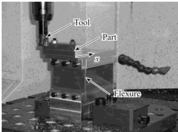
Mechanical model
A schematic diagram of the milling process is shown in Figure 2. The structure is assumed to be flexible in the x direction that is perpendicular to the feed.
The governing equation for the single degree of freedom oscillator model is: ( ) ( ) ( ) x( )
mx t cx t kx t F t , (5)
where m is the modal mass, c is the damping, k is the stiffness and F tx( ) is the x component of the cutting force. According to the linear cutting law (Insperger et al., 2003), the x component of the force is given by:
1 ( ) ( cos sin ) ( ) z x p R j T j j j F t A K K h t
, (6)where Ap is the axial depth of cut, j is the angular position of the jth cutting edge and KT and KR are the specific tangential and radial cutting coefficients. The chip thickness is expressed by:
( ) ( ) sin ( ) ( ( )) cos
j j z j j
h t g t f x t x t t , (7)
where, fz is the feed per tooth, x t( ) is the current position of the tool and x t( ( ))t is the
speed variation. The function g tj( ) is a screen function, it is equal to 1 when the tooth j is cutting, otherwise it is equal to 0:
1 ( ) 0 st j ex j if g t otherwise , (8)
where and st is the start and exit angles of the tooth j. ex
Stability analysis
Stability of the milling process with variable spindle speed can be estimated theoretically via the analysis of the governing Equations (5), (6) and (7). These equations imply the delay-differential equation in the form:
( )t ( ) ( )t t ( ) (t t( )),t x A x B u (9) where
0 1 0 ( ) ( ) , ( ) ( ) , ( ) ( ) , ( ) ( ( )) ( ( )) 0 , p p x t t t H t A k c t H t A x t m m m m t t x t t x A B u (10) with 1( ) z j( ) Rcos j Tsin j cos j j H t g t K K
. (11) If the modulation period Tv is rationally related to the mean time delay 0 = 60/(zN0), i.e.,pTv=q0 with p and q being relative primes, then the system is purely periodic at period
T=pTv=q0. For this case, the Floquet theory of delayed systems can be applied with the principal
Floquet theory does not apply. A triangular shape variation with p=4 and q=15 is shown in Figure 3. For this example, the amplitude variation is 20% and the RVF=0.8. The evolution of the function H(t) is also presented. The principal period is T=4Tv=150, i.e., 15 tooth passes spaced
with variable delays (t) occur during the period of four speed modulations period.
In the current analysis, parameters are selected so that Tv and 0 are rationally related and the
Floquet theory can be applied. This assumption may seem restrictive, since these two parameters are in general not rationally related, and the system is therefore quasi-periodic. Still, this assumption will be used in the analysis. The explanation is that for any pair of Tv and 0, one can
give a rationally related pair T and v (i.e., 0 pTv q with p and q being integers) that are close 0
enough to the original pair Tv and 0. From practical point of view, it is reasonable to assume that
the behaviour of the two systems are similar, although the mathematical theorems for the stability analysis of the quasi-periodic systems are more difficult than they are for the periodic system with Tv and . According to the Floquet theory, the stability of a time-periodic system is 0 determined by the eigenvalues of the associated monodromy operator. If all the eigenvalues are in modulus less than 1, then the system is asymptotically stable. In general, this operator is infinite dimensional with infinitely many eigenvalues, but it can be approximated by finite dimensional matrices. Here, we apply the semi-discretization according to Insperger et al. (2008) to derive stability properties. This method was previously validated by time domain simulations for milling processes by Seguy (2008).
SELECTION OF OPTIMAL PARAMETERS Optimal area
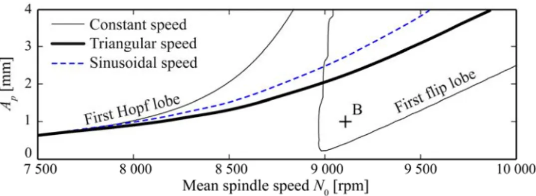
Stability lobes can be constructed numerically by scanning the cutting conditions (spindle speed and axial depth of cut) for a couple of (RVA, RVF) parameters. Figure 4 presents the lobes for constant, triangular and sinusoidal spindle speeds at the region of the first flip and first Hopf lobes. The critical depth of cut can be seen to be increased by speed variation for some ranges of spindle speeds, but for some other ranges, the critical depth of cut is less than that of the constant spindle speed. For example, a cutting process with an axial depth of cut of 1 mm and a spindle speed of 9100 rpm – that is unstable for constant spindle speed – can be stabilized by a speed variation. Globally, the critical depth of cut can essentially be increased in the area of the first flip lobe by spindle speed variation. We did not test all cases to make a complete generalization, but we have given the various simulations that seem to be quite general.
Comparison of the shape variation
The effectiveness of the spindle speed variation is tested on the flip lobe area (N0 = 9100 rpm)
with a triangular and sinusoidal shape variation. Figure 5 shows a contour plot presenting the maximal depth of cut available without chatter for the amplitude (vertical axis) and frequency (horizontal axis) with an average spindle speed of 9100 rpm. At constant speed, the maximal depth of cut is 0.5 mm. It can be seen that the triangular shape always increases the critical depth of cut Ap for any RVA and RVF values. For some domains, even Ap = 2.4 mm can be achieved
that corresponds to 380% improvements. As mentioned earlier, the choice of the frequency and the amplitude variation is limited by the spindle dynamics. We measured that within the range of variation (0-4 Hz), the maximum measured acceleration of the spindle is 100 rev/s2, i.e., 6000
rpm/s. Considering the limits of the dynamic spindle for the triangular shape, the optimal choice is to use low frequency modulation with high amplitude. Such a point is denoted by point C.
A similar plot is determined for a sinusoidal shape in Figure 6. Like the triangular shape, the sinusoidal shape always increases the critical depth of cut. For some areas, an improvement of 500% can be achieved (Ap = 3 mm). This simulations show that, for the same frequency and
amplitude parameters, the sinusoidal shape is more effective than the triangular shape. However, considering the spindle acceleration, then the sinusoidal shape would give only a maximum improvement of 300% (compare the spindle limits in Figures 5 and 6). Thus, for the machinist, a triangular speed modulation would be more effective.
It can be seen that the dependence of the maximum depth of cut on the modulation frequency is not so strong as on the modulation amplitude. Application of a large RVF coupled with a low
RVA does not provide any improvement in the depth of cut at all. In order to explore more
precisely the potential of spindle speed variation, a similar diagram was determined for large modulation frequencies with a triangular shape (see Figure 7). The frequency variation was increased up to the mean tooth passing frequency 1/0. For RVF = 1, the spindle makes one
complete variation period during a single tooth pass. In fact this case corresponds to a very fast variation and is not relevant for practical applications. Figure 7 shows that the improvements in the high frequency domain are low. It can be seen that for lower frequencies there are domains bounded by the specific lines in the form RVA = k × RVF, where the depth of cut significantly increases and reaches 2.5-3.5 mm (that corresponds to 400-600% improvements). However, for the higher frequencies the maximum depth of cut remains around 0.5 mm, except for some punctual areas, where, again, large depths of cut (about 2.5-3.5 mm) can be achieved. Overall, it
can be stated that it is not effective working in the high frequency domains, since the resulting gains are modest compared to the constant spindle speed case.
Based on the above numerical studies, it can be concluded that the triangular modulation allows – for a given spindle dynamics – the maximal gain for the machinist. For this reason, only triangular shaped modulation experiments will be shown here. In Figure 5, it was shown that the critical depth of cut can essentially be increased around the first flip lobe. Furthermore, the improvements were found to depend mostly on the amplitude of the speed variation, and dependence on frequency was modest, even for the high frequency range.
EXPERIMENTAL WORK
The cutting tests were conducted on a 3 axis high-speed milling center (Huron, KX10). The tool was an inserted mill with three teeth, 25 mm diameter without helix angle. The average feed per tooth was 0.1 mm/tooth. The spindle speed modulation was controlled by a sub-program using a synchronous function (Siemens 840D). According to manufacturers, spindle speed variation has no negative effect on the spindle's and the controller's lifetime.
A removable part in aluminium alloy (2017A) was machined with a radial depth of cut (Ae) of
2 mm. For such a small radial immersion, the number of cutting teeth engaged to the workpiece is changing between 0 and 1. Figure 8 shows the experimental set-up. The workpiece was fixed to a flexure that was compliant in the x direction in order to assure the single degree of freedom system. The tool was considered to be rigid compared to the flexure. The vibrations of the part were measured by a laser velocimeter (Ometron, VH300+). Filtering was achieved with a high pass filter, Butterworth 14 order type, with a 50 Hz cutoff frequency. This numerical filtering was followed by a numerical integration with the ode45 solver (Simulink ®). The measurement of the static displacements is not possible using a velocimeter signal, especially for machining
conditions where laser beam may be crossed by particles. This filtering is coherent with the chatter phenomenon studied, mainly over 100 Hz. A 3D profilometer (Optical Profil, WYKO NT 1100) was used to measure the surface roughness.
The dynamic parameters of the system were obtained by hammer impact test. The cutting force coefficients were determined according to Seguy et al., 2008. The dynamic parameters and the cutting force coefficients are summarized in Table 1.
Constant spindle speed test
In order to verify the model, a series of tests at a constant speed has been conducted. The experimental results have been superimposed onto a plot of the theoretical stability predictions in Figure 9. Cutting tests were declared stable if the 1/rev sampled position of the part approached a steady constant value (Bayly et al., 2003) this information was also correlated by frequency analysis. Stable cutting tests are denoted by circle while unstable tests by crosses. The predicted behaviour of the system agrees well with the experiments. The classical Hopf lobes were just checked by some focused tests, while, the area of period doubling chatter at the 1st flip lobe was explored using a finer resolution of the spindle speed.
High frequency spindle speed variation
Cutting tests were conducted at spindle speed of 9100 rpm with RVA = 0.005, RVF = 0.15 (fv = 22.75 Hz) and a depth of cut of 1 mm. In this range of variation (20-25 Hz), the maximum
acceleration of the spindle was measured: 70 rev/s2, i.e., 4200 rpm/s. The results are presented in
Figure 10. Test (A) refers to the variable speed machining (see point A in Figure 7 and Figure 9), test (B) to the constant spindle speed machining (note that these cutting parameters are in the first flip lobe, see point B in Figure 4). It can be seen that both cutting tests are unstable in accordance
the same for both the constant and the varying spindle speeds, and both machining operations have generated similarly poor surface roughness on the workpiece. These cases demonstrate that high frequency of the spindle speed modulation has a minor effect on the performance.
Low frequency spindle speed variation
In this section, cutting tests are presented where the frequency of the speed modulation is low, about 1 Hz. Consider the machining process with spindle speed 9100 rpm and depth of cut 1 mm. For constant spindle speed, this process is unstable (see Figure 4). For high frequency spindle speed variation with low amplitude (RVA = 0.005, RVF = 0.15), the chatter still develops, i.e. the system is still unstable. Here, we apply the spindle speed variation according to point C in Figure 5. The corresponding parameters are RVA = 0.2, RVF = 0.0046875 (fv = 0.71 Hz). Based on the
theoretical predictions in Figure 5, the corresponding critical depth of cut is about 2 mm, thus the machining operation with depth of cut 1 mm is predicted to be stable. Figure 11 presents the experimental results obtained for the cutting test with low frequency spindle speed variation that confirms the theoretical prediction.
At constant spindle speed (see Figure 12), chatter was clearly identified (Test B). The amplitude of the vibrations was about 0.07 mm. While the application of high frequency spindle speed variation with RVA = 0.005 and RVF = 0.15 does not result in any improvement in the stability at all (see Figure 10), low frequency modulation of the spindle speed with RVA = 0.2 and
RVF = 0.0046875 stabilizes the process and reduces the amplitudes of the vibrations to 0.01 mm
(see Figure 11).
The feed per tooth was 0.1 mm for all machining operations. Without vibrations, the three fluted tool would leave a machined profile of pitch 0.3 mm due to the runout (since the profile is generated by the tooth with the maximum radial runout). For the constant speed cutting in Figure
12, this pitch is 0.6 mm, which refers to the period doubling phenomena, i.e., this mark is left after two complete rotation of the tool. The corresponding surface roughness was 3.7 μm. This phenomenon is clearly presented on the 3D view of the machined surface in Figure 12.
During the tests with low frequency spindle speed variation, no chatter was observed (see Figure 11). In this case, the pitch is 0.3 mm, i.e., the profile was generated during a single rotation of the tool. The surface roughness was reduced to 1.75 μm that corresponds to 50% improvement. The 3D view in the Figure 11 shows a smoother machined surface, as well.
7
CONCLUSIONS
In this paper, variable spindle speed machining, on a single DOF system, was investigated for high-speed milling at the first flip lobes. Based on both numerical simulation and from experiments using specific cutting operation parameters, the following points can be concluded:
(1) The semi-discretization method is an effective and reliable method for the prediction of stability properties for milling operations with spindle speed variation.
(2) Triangular and sinusoidal speed modulations were compared in order to find the optimal technique to suppress chatter. It was found that the sinusoidal shaped modulation is more effective than the triangular one, for the same amplitude and frequency parameters. However, for the same spindle dynamics the triangular shape allows larger modulation amplitude. In fact, the triangular shape allows the maximal gain for the machinist.
(3) Spindle speed variation technique was analyzed for different variation amplitudes and frequencies. It was found that the critical depth of cut increases mainly with the amplitude of the variation, while the frequency of the variation has no significant effect on the dynamic behaviour
of the process even in the case of high frequency variation reaches RVF≈1. The amplitude of the speed variation is more important from stability point of view than its frequency.
(4) The stabilization effect of spindle speed variation was confirmed by experiments. Chatter was effectively suppressed by applying low frequency spindle speed variation, while the process was unstable both for constant speed variation and for high frequency spindle speed variation.
(5) The surface roughness of the machined workpiece was improved when the spindle speed variation was applied.
(6) Finally, it should be noted that in practice it might be easier to change the spindle speed to stable parameter domains rather than applying spindle speed variation, which is highly power consuming. However, on a complex part with multiple modes, the structure of the stability diagram is complex and usually unknown for the machinist. Find a stable "window" in the stability lobe diagram is not a trivial task, if it’s possible. In these cases, the application of spindle speed variation may be more practical than searching for stable spindle speeds. Furthermore, the spindle speed is often limited by other technological factors. In this context, spindle speed variation is an extra tool in addition to the traditional methods that can be used in the complex optimization of machining processes.
ACKNOWLEDGMENTS
This work was partly supported by the European Union Interreg IIIa AEROSFIN, by the Midi-Pyrénées Region Project "Complex workpiece machining in aeronautical context", and by the János Bolyai Research Scholarship of the HAS and by the HSNF under grant no. OTKA K72911. The authors would also like to thank Vincent WAGNER for his help on data processing.
NOMENCLATURE
Ae radial depth of cut, [m] Ap axial depth of cut, [m] c modal damping, [Ns/m]
fv frequency of the spindle speed variation, [Hz] fz feed per tooth, [m]
Fx(t) component of the cutting force in the x direction, [N]
( ) j
g t screen function of the tooth, 1 if the tooth j is cutting, 0 otherwise, [-]
hj(t) chip thickness of the tooth j, [m]
H(t) specific cutting force coefficient, [N/m²] k modal stiffness, [N/m]
KR specific radial cutting coefficient, [N/m²] KT specific tangential cutting coefficient, [N/m²] m modal mass, [kg]
mod(t,Tv) modulo function, [-]
N0 mean value of the spindle speed variation, [rpm]
Na amplitude of the spindle speed variation, [rpm] p, q relative primes numbers, [-]
RVA ratio of variation amplitude, [-] RVF ratio of variation frequency, [-]
S(t) shape function of the spindle speed variation, [-] Tv period of the spindle speed variation, [s]
ex
exit angle of the tooth j, [rad]
j
angular position of the jth cutting edge, [rad]
st
start angle of the tooth j, [rad]
0 mean time delay, [s]
( )t
variable time delay, [s]
REFERENCES
Al-Regib, E.; Ni, J.; Lee, S.H. (2003) Programming spindle speed variation for machine tool chatter suppression. International Journal of Machine Tools and Manufacture, 43:1229– 1240.
Altintas, Y.; Budak, E. (1995) Analytical prediction of stability lobes in milling. Annals of the CIRP, 44:357–362.
Altintas, Y.; Chan, P.K. (1992) In-process detection and suppression of chatter in milling. International Journal of Machine Tools and Manufacture, 32:329–347.
Altintas, Y.; Engin, S.; Budak, E. (1999) Analytical stability prediction and design of variable pitch cutters. Transactions of the ASME, Journal of Manufacturing Science and Engineering, 121:173–178.
Bayly, P.V.; Halley, J.E.; Mann, B.P.; Davies, M.A. (2003) Stability of interrupted cutting by temporal finite element analysis. Transactions of the ASME, Journal of Manufacturing Science and Engineering, 125:220–225.
Bediaga, I.; Egaña, I.; Muñoa, J. (2006) Reducción de la inestabilidad en cortes interrumpidos en fresado a alta velocidad mediante variación de la velocidad del husillo. In XVI Congreso de Máquinas-Herramienta y Tecnologías de Fabricación, San Sebastián, Spain.
Budak, E. (2003) An analytical design method for milling cutters with nonconstant pitch to increase stability, Part I: Theory. Transactions of the ASME, Journal of Manufacturing Science and Engineering, 125:29–34.
Insperger, T.; Mann, B.P.; Stépán, G.; Bayly, P.V. (2003) Stability of up-milling and down-milling, part 1 : alternative analytical methods. International Journal of Machine Tools and Manufacture, 43:25–34.
Insperger, T.; Stépán, G. (2004) Stability analysis of turning with periodic spindle speed modulation via semidiscretization. Journal of Vibration and Control, 10:1835–1855.
Insperger, T.; Stépán, G.; Turi T. (2008) On the higher-order semi-discretizations for periodic delayed systems. Journal of Sound and Vibration, 313:334–341.
Lin, S.C.; DeVor, R.E.; Kapoor, S.G. (1990) The effects of variable speed cutting on vibration control in face milling. Transactions of the ASME, Journal of Engineering for Industry, 112:1–11.
Merdol, S.D.; Altintas, Y. (2004) Multi frequency solution of chatter stability for low immersion milling. Transactions of the ASME, Journal of Manufacturing Science and Engineering,
Paris, H.; Peigné, G.; Mayer, R. (2004) Surface shape prediction in high speed milling. International Journal of Machine Tools and Manufacture, 44:1567–1576.
Sastry, S.; Kapoor, S.G.; DeVor, R.E. (2002) Floquet theory based approach for stability analysis of the variable speed face-milling process. Transactions of the ASME, Journal of Manufacturing Science and Engineering, 124:10–17.
Seguy, S.; Insperger, T.; Arnaud, L.; Dessein G.; Peigné, G. (2010) On the stability of high-speed milling with spindle speed variation. International Journal of Advanced Manufacturing Technology, 48:883–895.
Seguy, S. (2008) From the spindle speed selection to the spindle speed variation for chatter control in thin wall milling: modelling and experiments (in French), PhD University of Toulouse, France.
Seguy, S.; Campa, F.J.; López de Lacalle, L.N.; Arnaud, L.; Dessein, G.; Aramendi, G. (2008) Toolpath dependent stability lobes for the milling of thin-walled parts. International Journal of Machining and Machinability of Materials, 4:377–392.
Sexton, J.S.; Milne, R.D.; Stone, B.J. (1977) A stability analysis of single point machining with varying spindle speed. Applied Mathematical Modelling, 1:310–318.
Sexton, J.S.; Stone, B.J. (1980) An investigation of the transient effects during variable speed cutting. Journal of Mechanical Engineering Science, 22:107–118.
Takemura, T.; Kitamura, T.; Hoshi, T.; Okushima, K. (1974) Active suppression of chatter by programmed variation of spindle speed. Annals of the CIRP, 23:121–122.
Tobias, S.A.; Fishwick, W. (1958) Theory of regenerative machine tool chatter. Engineer, 205:199–203 238–239.
Tsao, T.C.; McCarthy, M.W.; Kapoor, S.G. (1993) A new approach to stability analysis of variable speed machining systems. International Journal of Machine Tools and Manufacture, 33:791–808.
Zatarain, M.; Bediaga, I.; Muñoa, J.; Lizarralde, R. (2008) Stability of milling processes with continuous spindle speed variation: analysis in the frequency and time domains, and experimental correlation. Annals of the CIRP, 57:379–384.
Zhang, H.; Jackson, M.J.; Ni, J. (2009) Stability analysis on spindle speed variation method for machining chatter suppression. International Journal of Machining and Machinability of Material, 5:107–128.
LIST OF FIGURES CAPTIONS
Fig. 2: Mechanical model of the milling process.
Fig. 4: Stability diagrams for variable speed milling with RVA = 0.3 and RVF = 0.003.
Fig. 6: Parametric study for sinusoidal shape for N0 = 9100 rpm and Ae = 2 mm.
Fig. 8: Experimental set-up.
Fig. 12: Constant spindle speed machining for Ap = 1 mm and N0 = 9100 rpm.
LIST OF TABLE
Table 1: Flexure modal parameters and cutting coefficients.
k [N/m] f [Hz] ξ [%] KT [MPa] KR [MPa]